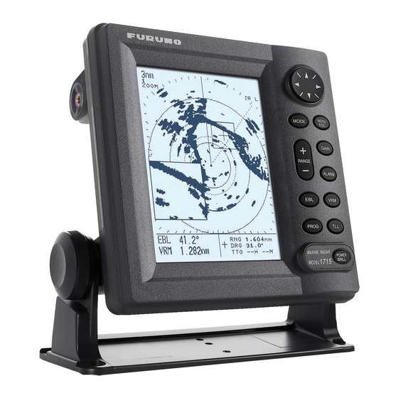
Furuno 1715 Operator's Manual
Furuno marine radar user manual
Hide thumbs
Also See for 1715:
- Service manual (44 pages) ,
- User manual (33 pages) ,
- Operator's manual (2 pages)
Table of Contents
Advertisement
Advertisement
Table of Contents
Troubleshooting

Related Manuals for Furuno 1715


Summary of Contents for Furuno 1715
- Page 1 OPERATOR'S MANUAL MARINE RADAR MODEL 1715 MODEL www.furuno.co.jp...
- Page 2 (http://www.eiae.org/) for the correct method of disposal. How to discard a used battery Some FURUNO products have a battery(ies). To see if your product has a battery, see the chapter on Maintenance. Follow the instructions below if a battery is used. Tape the + and - terminals of battery before disposal to prevent fire, heat generation caused by short circuit.
- Page 3 WARNING LABEL A warning label is attached to the equipment. Do not remove the label. If the label is missing or damaged, contact a FURUNO agent or dealer about replacement. Name: Warning Label (1) WARNING Type: 86-003-1011-1 To avoid electrical shock, do not remove cover.
- Page 4 COMPLIANCE WITH R&TTE DIRECTIVE 1999/5/EC This radar complies with the R&TTE Directive 1999/5/EC. In accordance with Article 6-3 of this directive, FURUNO intends to put this radar on the market of the following countries in EU as well other markets.
-
Page 5: Table Of Contents
TABLE OF CONTENTS FOREWORD ...v SYSTEM CONFIGURATION ...vi EQUIPMENT LISTS ...vii 1. OPERATION ... 1 1.1 Controls ... 1 1.2 Indications ... 2 1.3 Turning Power On/Off... 3 1.4 Transmitting, Standby... 3 1.5 Adjusting Display Contrast, Brilliance ... 4 1.6 Choosing the Range... 4 1.7 Receiver Sensitivity ... -
Page 6: Foreword
The main features of the MODEL 1715 are • Daylight viewing radar specially designed for small craft and sailing yachts. -
Page 7: System Configuration
MODE WIND INDICATOR, GAIN SPEED INDICATOR RANGE ALARM PROG or ECHO SOUNDER MARINE RADAR POWER 1715 MODEL BRILL EXTERNAL BUZZER XH3-BZ-L970 : Standard supply : Optional supply : Local supply *: The optional 30 m antenna cable is available for 24 VDC ship's mains only. -
Page 8: Equipment Lists
EQUIPMENT LISTS Standard supply Name Type Antenna Unit RSB-0095-076 Display Unit RDP-142 CP03-25301 CP03-24910 Installation CP03-24920 Materials CP03-24930 CP03-25101 Spare Parts SP03-14301 Template (1) C32-00302 Template (2) C32-00303 Optional supply Name Cable Assy. XH3-BZ-L970 Cable Assy. MJ-A7SPF0007-050 Cable Assy. MJ-A15A7F0004-005 Cable Assy. -
Page 9: Operation
Turns VRM on/off. Shortcut key Outputs chosen target’s L/L PROG position to plotter. MARINE RADAR POWER 1715 MODEL BRILL Short press: Turns power on. Long press: Turns power off. Momentary press: Opens dialog box for (power turned on) adjustment of display... -
Page 10: Indications
1.2 Indications Simulation mode Range Range ring interval ZOOM WATCH Zoom Watchman Guard zone Cursor Position Speed Speed EBL/VRM Box EBL 45.0 EBL bearing VRM 5.033 VRM range Appropriate sensors required to display nav data. About the LCD The high quality LCD displays better than 99.99% of its picture elements. The remaining elements may drop out or light, however this is not an indication of malfunction;... -
Page 11: Turning Power On/Off
[POWER/BRILL] key to continue. If the equipment does not work properly, contact your dealer for advice. 7" LCD MARINE RADAR MODEL 1715 FURUNO ELECTRIC CO., LTD. ROM : OK RAM : OK Program No: 0359199-XX.XX XX.XX = Program version no. -
Page 12: Adjusting Display Contrast, Brilliance
1.5 Adjusting Display Contrast, Brilliance 1. With the power turned on, press the [POWER/BRILL] key momentarily to show the brilliance/contrast adjustment window. BRILL/CONTRAST TX/ST-BY - PRESS [MODE] CONT: BRILL: [MENU/ESC] : Exit. Brilliance/contrast adjustment window 2. Press ◄ or ► to adjust contrast. 3. -
Page 13: Suppressing Sea Clutter
1. OPERATION Manual gain adjustment While observing the screen and the gain tuning bar, press ◄ or ► to adjust the gain. The setting range is 0-100. 3. Press the [MENU/ESC] key to finish. 1.8 Suppressing Sea Clutter Echoes from waves cover the central part of the display with random signals known as sea clutter. -
Page 14: Suppressing Rain Clutter
Manual A/C SEA adjustment While observing the screen and the A/C SEA tuning bar, press ◄ or ► to adjust the A/C SEA. The setting range is 0-100. 3. Press the [MENU/ESC] key to finish. 1.9 Suppressing Rain Clutter The vertical beamwidth of the antenna is designed to see surface targets even when the ship is rolling. -
Page 15: Measuring The Bearing
1. OPERATION 1.11 Measuring the Bearing The bearing to a target can be measured with the cursor and the EBL (Electronic Bearing Line). Measuring bearing with the cursor Operate the cursor pad to place the cursor on the center of the target. Read the bearing to the target at the bottom right corner. -
Page 16: Zoom
1.13 Zoom The zoom feature allows you to double the size of a selected area. If zoom is activated when nav data is displayed, the nav data is automatically erased. 1. Use the cursor pad to place the cursor where you want to zoom. 2. -
Page 17: Heading Line
1. OPERATION User menu description Item Description TX/ST-BY Sets radar in transmit or stand-by status. (Same functions as the [MODE] key.) Rejects radar interference. REJECTION ECHO Stretches echoes in range STRETCH direction or range and bearing direction. Suppresses long-range rain clutter. -
Page 18: Noise Rejector
1.17 Noise Rejector The noise rejector suppresses white noise, which appears on the screen as many dots scattered randomly over the display. 1. Press the [MENU/ESC] key to open the User menu. 2. Press ▲ or ▼ to choose NOISE REJECTION from page 1. -
Page 19: Guard Alarm
1. OPERATION 1.20 Guard Alarm The guard alarm allows the operator to set the desired range and bearing for a guard zone. When ships, islands, landmasses, etc. violate the guard zone, audio and visual alarms are released to call your attention. The alarms will be released for targets entering or exiting the zone depending on the presence or absence of targets in the zone... -
Page 20: Watchman
1.21 Watchman How watchman works Watchman transmits the radar for one minute to check if a target has entered or exited the guard zone from the previous transmission. If no change is found, the radar goes into stand-by for the number of minutes set for the watchman feature. -
Page 21: Hue
1. OPERATION 1.24 Hue The default hue setting (DAY) displays echoes in tones of gray on a white background, which is most suitable for daytime viewing. For nighttime viewing you may reverse this arrangement. 1. Press the [MENU/ESC] key to open the User menu. -
Page 22: Turning Navigation Data On/Off
1.28 Turning Navigation Data On/Off Navigation data appears on the bottom half of the screen as in the illustration below. You may turn the navigation data display on or off as shown below. Note: When the nav data is turned on with shift or zoom active, zoom or shift is cancelled. - Page 23 1. OPERATION GRAPHIC DISPLAYS Digital XTE 0.25 Analog XTE (Bar moves right or left according to amount and direction of XTE) XTE (Cross-Track Error) GRAPHIC Speed 17.2 SPEED GRAPHIC Wind APP* 10.3 Speed WIND GRAPHIC Waypoint 03 Destination Rng 0.19nm Brg 321 XTE 0.00nm Cse 333...
-
Page 24: System Menu
1.30 System Menu The System menu mainly contains items which once set do not require frequent adjustment. You may display this menu by choosing “SYSTEM MENU” from page 2 of the User menu and then pressing ►. SYSTEM MENU PAGE 1 LANGUAGE English RANGE UNIT... - Page 25 1. OPERATION PANEL DIMMER, HUE, TRIPLOG RESET: See paragraph 1.23, 1.24, 1.25, respectively. Page 2 of system menu EBL REFERENCE: The EBL readout may be chosen from relative (relative to own ship’s heading) or true (referenced to the North). Heading data required for true bearing. Note: If no bearing data is input, course data from the GPS navigator is used.
-
Page 26: Maintenance, Troubleshooting
2. MAINTENANCE, TROUBLESHOOTING 2.1 Maintenance Regular maintenance is important for good performance. A maintenance program should be established and should at least include the items listed in the table below. Period Item Fixing bolts for antenna unit Antenna unit cleanliness Antenna unit cover 3 to 6... -
Page 27: Replacing The Fuse
2.2 Replacing the Fuse The fuse (5 A) in the power cable protects the equipment against reverse polarity of the ship’s mains, overcurrent, and equipment fault. If the fuse blows, find the cause before replacing it. Use the proper fuse. Use of a wrong fuse may cause serious damage to the equipment and void the warranty. -
Page 28: Diagnostics
NMEA Body: 39 ° GPS (XXXXXXX-XX.XX)*: OK Program No. 0359199-**.** Push [MENU] 3 times to exit. * Program no. of FURUNO BlackBox GPS GP-310B: 48502180XX XX = Program GP-320B: 48502380XX Version No. **.** = Program version no. Diagnostic test results... -
Page 29: Test Pattern
When the synchro belt has worn out, the sweep is not synchronized with antenna rotation, which results in an abnormal picture. When you suspect that the synchro belt has worn out, contact a FURUNO agent or dealer about replacement. (Type: 40 S2M 266UG, Code No: 000-808-743) FOUR-TONE... -
Page 30: Installation
3. INSTALLATION NOTICE Do not apply paint, anti-corrosive sealant or contact spray to coating or plastic parts of the equipment. Those items contain organic solvents that can damage coating and plastic parts, especially plastic connectors. 3.1 Antenna Unit Installation Mounting considerations When choosing a mounting location for the antenna unit, keep in mind the following points:... - Page 31 3. Use the flat washers and spring washers removed earlier and appropriate hex bolts (see the illustration below) to fasten the antenna unit to the platform. The torque should be between 19.6-24.5 N m. Flat washer Spring Apply silicone washer Hex bolt sealant.
- Page 32 3. INSTALLATION 8. Tighten the cable gland to fix the antenna cable. Gasket Cable Gland Tighten gland so this length is within 12 mm. Antenna unit, inside view 9. Referring to the figure below, fasten the shield cable with a screw (M4 x 10) on the chassis to ground the unit.
-
Page 33: Display Unit Installation
M8 x 20 Mounting plate M8 x 20 Bracket (1) Fixing plate Bracket (2) M8 x 20 M4 x 12 (A) Assembling the mounting bracket M10 x 25 (B) Fastening antenna to mounting bracket How to assemble the optional mounting bracket and mount the antenna 4. -
Page 34: Wiring
3. INSTALLATION 3.3 Wiring Connect the antenna cable, the power cable and the ground wire as shown below. ANTENNA UNIT External Equipment (NMEA) NMEA NMEA DJ-1 DJ-1 POWER POWER 12-24 VDC 12-24 VDC DISPLAY UNIT FUSE (5 A) GROUND Connect ground WHT (+) wire to bolt fastened (or welded) to hull. -
Page 35: Adjustments
Note: This procedure requires making a hole in the display unit, which can affect watertightness. FURUNO cannot guarantee watertight integrity after this modification is made. 1. Detach the rear panel and place it out side up on a workbench. -
Page 36: Timing Adjustment
3. INSTALLATION 6. Press ► to show the Radar Setup menu. RADAR SETUP HEADING ADJUST TIMING ADJUST SET ON TIME : 000000h SET TX TIME : 000000h [MENU/ESC]: Exit. Radar setup menu 7. HEADING ADJUST is selected; press ► to show the options window. RADAR SETUP HEADING ADJUST : YES... - Page 37 3. Press ▲ to choose YES, and the display now looks as below. Message SWEEP TIMING ADJUSTMENT BY ’ ’ AND ’ ’ KEYS. THEN PUSH MODE KEY TO SET. Timing adjustment display 4. Find a target which should be “straight” (harbor wall, straight pier) on the radar display.
-
Page 38: Magnetron Heater Voltage
3. INSTALLATION 3.5 Magnetron Heater Voltage Magnetron heater voltage is formed at the MD Board of the antenna unit and is preadjusted at the factory. Therefore, no adjustment is required. However, verify the voltage as below. WARNING ELECTRICAL SHOCK HAZARD Do not open the equipment. -
Page 39: Menu Tree
MENU TREE MENU/ESC TX/ST-BY (TX, ST-BY ) INT REJECTION (OFF, LOW , MEDIUM, HIGH) ECHO STRETCH (OFF, LOW , HIGH) FTC ( OFF , ON) NOISE REJECTION (OFF, LOW , HIGH) WATCHMAN TIME ( OFF , 5, 10, 20 min) HDG LINE OFF (Temporarily turns off heading line.) ECHO TRAIL ( OFF , 30 s;... -
Page 40: Specifications
Ring Interval 0.0625 0.125 0.125 0.25 0.25 0.5 Number of Rings Range unit: nm/sm/km selectable, 0.125: nm/sm only, 36: km only MODEL 1715 PPI daylight display, raster scan, 4 tones in monochrome 0.125, 0.25, 0.5, 0.75 1, 1.5, 2 0.08 μs (short) 0.3 μs (medium) - Page 41 Markers Alphanumeric Indications Range, Range Ring Interval, Interference Rejection (IR), Input Sentences Output Sentences ENVIRONMENTAL CONDITIONS Ambient Temperature Relative Humidity Waterproofing Bearing Vibration POWER SUPPLY 12-24 VDC: 3.5-1.6 A COATING COLOR Display Unit Antenna Unit COMPASS SAFE DISTANCE Display Unit Antenna Unit Heading Line, Bearing Scale, Range Rings, Variable Range Marker (VRM), Electronic Bearing Line (EBL),...
- Page 48 : +81-(0)798-65-4200 Printed in Japan All rights reserved. Pub. No. OME-35140-C3 (YOSH ) MODEL1715 The paper used in this manual is elemental chlorine free. ・FURUNO Authorized Distributor/Dealer A : AUG C3 : MAR . 03, 2011 *00014790912* *00014790912* *00014790912* *00014790912*...
Need help?
Do you have a question about the 1715 and is the answer not in the manual?
Questions and answers