Table of Contents
Advertisement
Quick Links
Advertisement
Table of Contents

Related Manuals for Handicare Ibis


Summary of Contents for Handicare Ibis
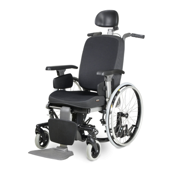
- Page 1 SERVICE MANUAL IBIS...
- Page 2 Handicare accepts no liability for loss resulting from work executed by third parties. Names, trade names, etc. used by Handicare may not, as per the legislation concerning the protection of trade names, be considered as being available.
-
Page 3: Table Of Contents
2.2.4 Replacing the tyre of the rear wheel ....................8 2.2.5 Adjusting the pressure brake ......................9 Replacement and repair activities for the Ibis with 12” or 16” rear wheels and PowerSupport ....9 2.3.1 Rear wheels ........................... 9 2.3.2 Replacing the 12”... -
Page 4: This Manual
This manual This manual This manual contains the basic instructions for repairs and general maintenance of the Ibis manually operated wheelchair. Mechanics who do repairs on this wheelchair must be well trained and familiar with the repair methods and the maintenance of the Ibis wheelchair. - Page 5 In case of any defects the User is required –within two weeks after discovery of the defect- to contact the dealer. He has to complete a return form and return the product or part via the RMA-process. Handicare will, at its sole discretion, take the corrective action it seems fit under the given circumstances within a reasonable period of time (depends on nature of claim) from receipt of the completed return form.
- Page 6 This manual Handicare will only accept shipment costs and corrective costs related to warranty on equipment during the warranty period. This warranty will void in case of: The product and/or its parts being modified or items having been added by others than Handicare;...
-
Page 7: Maintenance
It is recommended to have your wheelchair serviced by your dealer at least once a year, or, in case of intensive use, once every six months. Replacement and repair activities for the Ibis with 20”, 22” and 24” rear wheels 2.2.1 Rear wheels To ensure proper operation of the wheelchair, it is very important that the tyres are kept at the correct pressure. -
Page 8: Replacing Rear Wheels
Maintenance 2.2.2 Replacing rear wheels The rear wheels should be removed as follows: Remove locking nut (A) with a 17 mm box spanner. • Remove the complete rear wheel (B) from axle (C). • Remove the tyres, see ‘Repairing the tyre of the rear •... -
Page 9: Adjusting The Pressure Brake
- towards the wheel: brake tighter. Tighten the screw in the set position. • Replacement and repair activities for the Ibis with 12” or 16” rear wheels and PowerSupport 2.3.1 Rear wheels To ensure proper operation of the wheelchair, it is very important that the tyres are kept at the correct pressure. -
Page 10: Replacing The 12" Rear Wheel
‘Replacing the tyre of the drive wheel’. Fit the new wheel in the reverse order. 2.3.4 Replacing the rear wheel of Ibis with PowerSupport (option) When replacing a rear wheel, the wheel may not be braked. Replace the rear wheel as follows: Support the wheelchair in such a way that the wheel is •... -
Page 11: Repairing The Tyre Of The Rear Wheel
Maintenance 2.3.5 Repairing the tyre of the rear wheel When repairing the inner tube of a rear wheel, the wheel should be braked, so that it does not rotate at the same time. Repair a flat tyre as follows: Support the wheelchair in such a way that the wheel is elevated. •... -
Page 12: Adjusting The Brake Of The Ibis With 12" Rear Wheels
Maintenance 2.3.7 Adjusting the brake of the Ibis with 12” rear wheels The wheelchair is equipped with drum brakes on the rear wheels, which can be either operated by hand by the user, or with the foot by the person pushing the wheelchair. -
Page 13: Replacing The Controller Of The Ibis Powersupport (Option)
Maintenance 2.3.10 Replacing the controller of the Ibis PowerSupport (option) Replace the controller as follows: Cut the Ty-Raps that hold the cable. • Loosen three cross-head screws (A). • Remove the controller. Fit a new controller in the reverse order. -
Page 14: Replacing A Fork
Maintenance 2.4.2 Replacing a fork Replace the fork as follows: Remove the wheel from the fork; see 'Replacing a wheel'. • Remove screw (A) with a Phillips screwdriver. • Remove cap (B). • Loosen bolt (C) using a 19 mm box spanner and prevent •... -
Page 15: Technical Specification
Technical specifications Technical specification Description Diameter rear wheels 12” / 16” 20” / 22” / 24” Diameter front wheels 7” 7” Tyre pressure rear wheels 2,5 bar 7,5 bar Max. user weight 160 kg 160 kg Total length 1040 mm 1040 mm Total width 625 mm... -
Page 16: Software Upgrade Manual Powersupport
Software upgrade manual PowerSupport Software upgrade manual PowerSupport Installing the update software Start the “pssetup.exe” installation form the CD / USB stick. Choose English For an English Installation procedure and press “OK” . Press “Next >”. Version 2015v1... - Page 17 Software upgrade manual PowerSupport Select “Install for anyone using this computer” and press “Next >”. When “Install just for me” is selected, only the current user will be able to use the software. Select the destination folder for the software and press “Next >”. Version 2015v1...
- Page 18 Software upgrade manual PowerSupport Choose a Start Menu folder , for placing the shortcuts, and press “Next >”. Wait for the installation to finish and press “Next >”. Version 2015v1...
-
Page 19: Upgrading
Software upgrade manual PowerSupport Check the box in front of “Start PowerSupport Upgrader” off and press “Finish”. Upgrading 4.2.1 Why and when to upgrade The upgrade of the PowerSupport should be carried out when one of the following parts are replaced - Motor Left - Motor Right - Battery... -
Page 20: Connecting The Cables
Software upgrade manual PowerSupport 4.2.3 Connecting the cables Connect the COM-cable to the PowerSupport and to the laptop/pc. Activate the PowerSupport by turning the switch in to one of the levels and pressing the lever . 4.2.4 Upgrading the Software Star t the “PowerSupport Upgrader”... - Page 21 Software upgrade manual PowerSupport Now press on Communication and select the COM-Port that is used for the PowerSupport and press OK . Now select “File” and press “Open”. Now select the file you need for upgrading the PowerSupport , you can choose for a 5 or a 7- leveled version of the PowerSupport. These numbers correspond with the version of the PowerSupport you are upgrading.
- Page 22 Software upgrade manual PowerSupport When you get this error the version number of the PowerSupport is lower then 1.2. When this is the case you should first perform the PreUpgrade, therefore you should continue the upgrade from sect ion 3.2.5. Press “Start”...
-
Page 23: Upgrading With Preupgrade (Only For Version Number 1.1 And Older )
Software upgrade manual PowerSupport Press “OK” when the upgrade is completed to finish the upgrade. 4.2.5 Upgrading with PreUpgrade (Only for version number 1.1 and older ) Select “File” and the press “Open”. Now select the “PreUpgrade PMU.upk” and press “Open”. - Page 24 Software upgrade manual PowerSupport Press Start and wait for the PreUpgrade to finish. Now select “File” and the press “Open”. Now select the file you need for upgrading the PowerSupport, you can choose for a 5 or a 7- leveled version of the PowerSupport. These numbers correspond with the version of the PowerSupport you are upgrading.
- Page 25 Software upgrade manual PowerSupport Press Start and wait for the upgrade to finish. Press “OK” when the upgrade is completed to finish the upgrade. Version 2015v1...
-
Page 26: Checking The System
Software upgrade manual PowerSupport 4.2.6 Checking the system Disconnect the COM-Cable to the PowerSupport and check the following points - Turn the system on and check if the system goes on. - Does the system give support? - Is there a distinctive difference between the different levels? 4.2.7 Troubleshooting Has the check showed the system doesn’t function as it should or the Upgrade gave an... -
Page 27: Spare Parts
Spare parts Spare parts Use of the parts lists This document is meant as a reference book to be used to order parts for the wheelchair that is shown on the front cover. How to order When ordering parts, please specify: Serial number (see the identification plate) •... -
Page 28: Overview Spare Parts
07 Rear wheel 20” / 22” / 24” ..........................35 08 Rear wheel 12” ..............................36 5.3 Rear wheel 16” and Ibis PowerSupport ......................37 11 Brake system 16" rear wheel .......................... 37 12 Brake system Ibis PowerSupport ........................38 14 Rear Wheel 16"... -
Page 29: Sedeo Pro Seating System Interface
Spare parts Interface 01 Sedeo Pro seating system interface Article number Units Description 1 - 3 1010958 Seat frame Sedeo Pro Version 2015v1... -
Page 30: Carrier
Washer flat M8 D125A/vz 00000.4114 Hex bolt M8X60 9001140 Tube cap 1002789 Screw 4X16 1014931 Carrier front frame grey metallic 9006988 Label IBIS 1003247 Label back rest angle (sticker sheet) 9000872 Adhesive logo button 9002232 Handicare logo Identification plate 20-24 1008040 Anti tip (set) 00000.4311... -
Page 31: Seat Post
Spare parts 03 Seat post Article number Units Description 00000.4014 Cyl cap screw M6X50 02010.7682 Lower hinge block 22mm 1010958 Sedeo seating frame 00000.2002 Washer flat M6 DIN125A/VZ 1003247 Label seat height symbol (sticker sheet) 1015513 Seat angle indicator (P) 1008044 Seat angle indicator 1003247... -
Page 32: Brake System 20" / 22" / 24" Rear Wheel
Spare parts 04 Brake system 20” / 22” / 24” rear wheel Article number Units Description Lock nut M12 DIN 985 1,2,5,6,13 1015726 Wheel axle Washer flat M12 DIN 125-1a 3a,4,7-9,12,15 1015724 Wheel plate left 3b,4,7-9,12,15 1015725 Wheel plate right 1003247 Label wheels (sticker sheet) Lock nut M10 DIN 985... -
Page 33: Brake System 12" Rear Wheel
Spare parts 05 Brake system 12” rear wheel Article number Units Description 9000915 Wheel,12",air,with brake,assy,left 1002790 Wheel,12",PU,with brake,assy,left 9001076 Wheel,12",air,with brake,assy,right 1002791 Wheel,12",PU,with brake,assy,right 00000.1704 Locknut M12 D985/8/vz 9001199 Brake complete left 9001200 Brake complete right 00001.1409 Label footbrake 00000.1704 Lock nut M12 00000.2005 Washer flat M12... -
Page 34: Swivel Castor
Spare parts 06 Swivel Castor Article number Units Description 1008053 Front fork 00000.4310 Hex bolt M12X50 00000.6007 Shim 12X18X1 00000.1802 Cap lock nut M8 9002729 Lock nut M12 00000.4001 Cyl cap screw M8X75 1001446 Wheel,castor,7",air,assy 1001447 Wheel,castor,7",PU,assy Version 2015v1... -
Page 35: Rear Wheel 20" / 22" / 24
Spare parts 07 Rear wheel 20” / 22” / 24” Article number Units Description 03877.0100 Wheel 20" air 1002746 Wheel 20" PU 03875.0100 Wheel 22" air 1002748 Wheel 22" PU 03860.1100 Wheel 24" air 1002750 Wheel 24" PU 1003690 Tube 20" 1003691 Tube 22"... -
Page 36: Rear Wheel 12
Spare parts 08 Rear wheel 12” MAX. Article number Units Description 1001138 Wheel 12" air 1001166 Wheel 12" PU 1003689 Tyre 12" 01010.3300 Tube 12" 00001.1461 Label tyre pressure 2.5 Bar (sticker sheet) Version 2015v1... -
Page 37: Brake System 16" Rear Wheel
Spare parts Rear wheel 16” and Ibis PowerSupport 11 Brake system 16" rear wheel Article number Units Description 00000.1704 Lock nut M12 00000.2005 Washer flat M12 9001254 Interface plate 9001183 Brake assy left - double action 9001184 Brake assy right - double action... -
Page 38: Brake System Ibis Powersupport
Spare parts 12 Brake system Ibis PowerSupport MAX. Article number Units Description 001.03010.001 Hex bolt M10x40 00000.2004 Washer flat M10 1003706 Foot lever 9000995 Fixation block 1003707 Toothed spring washer M14 1003708 Cap lock nut M14 00000.5712 Distance bush nylon 8.2X12X7.5 00000.2003... -
Page 39: Rear Wheel 16
Spare parts 14 Rear Wheel 16" MAX. Article number Units Description 9002038 Wheel 16" air 9002039 Wheel 16" PU 1003693 Tyre 16" 1003694 Tube 16" 00001.1461 Label tyre pressure 2.5 Bar Version 2015v1... -
Page 40: Battery Pack
Spare parts 15 Battery pack Article number Units Description 00000.4036 Hex headcap screw m5x12 Din912 00000.2101 Washer flat 3xD M5 D9021/VZ 9005613 Frame mount Powersupport Battery pack 1003710 P-clip 7/8 00000.1700 Locknut M5 D985/8/VZ 1010223 Powersupport Battery pack 00000.3603 Screw cross recessed m6x16 Din965 00000.2102 Washer flat 3xD M6 D9021/VZ 00000.1701... -
Page 41: Remote Ibis Powersupport
Spare parts 16 Remote Ibis PowerSupport Article number Units Description 1010220 PowerSupport remote 1010224 PowerSupport remote housing (5 positions) 1008314 PowerSupport knob for speed potentiometer 1010221 PowerSupport throttle lever incl. spring 1015604 PowerSupport remote holder 9006240 Taptite M5x10 hex head flange... -
Page 42: Electrical Tilt
Spare parts Options 17 Electrical tilt Article number Units Description 1003391 Electrical tilt 00355.5573 AMP plug 2-polig 00000.1404 Shaft lock washer 7MM 9001398 Hinge block 9001509 Axle 9001282 Actuator for electrical tilt 9001128 Gasspring hinge block 00000.2203 Spring washer SW8 00000.4312 Hex bolt M8x16 00000.3608... -
Page 43: Electrical Lift
Spare parts 18 Electrical lift Article number Units Description 1-19 No longer available 00000.4014 Cyl cap screw M6X50 02010.6182 Upper block 00000.2002 Washer flat M6 DIN125A/VZ 02010.7682 Lower hinge block 22 mm No longer available 00000.3608 Screw M6X12 00000.1404 Shaft lock washer 7MM 9001398 Hinge block 9001154... -
Page 44: Supplementation Set For Electrical Adjustments
Spare parts 19 Supplementation set for electrical adjustments Article number Units Description 1-20 1015898 Supplementation set for electrical adjustments 008.00000.251 Sticker, Charger socket 00000.1700 Locknut M5 D985/8/VZ 00000.2101 Washer flat 3xD M5 D9021/VZ 4,5,6 1003284 Electrical control 00355.4301 Fuse holder 005.01190.000 Blade fuse 15A 9007369... -
Page 45: Coupled Push Brake 20" / 22" / 24" Rear Wheel
Spare parts 20 Coupled push brake 20” / 22” / 24” rear wheel Article number Units Description 1a,2,3a 9007291 Coupled push brake, left 1b,2,3b 9007292 Coupled push brake, right 9007280 Brake, passive, left 9007261 Brake, passive, right 9001515 Cable for coupled brake 9007260 Brake, active, left 9007279... -
Page 46: Tilt Operated By User
Spare parts 21 Tilt operated by user Article number Units Description 1008460 Self-tilt 60-90 kg 1-11 1008461 Self-tilt 90-120 kg Screw Cross recessed m5x12 Din965 1005144 Mounting plate tilt lever 1015330 Torx socket head screw M6x8 iso 14579 Precote 85 (100 pieces) 00000.6410 Handle tilt adjustment Nut M5 Self prevailing Din985... - Page 47 Drawing Position Changes Replaced the picture with ‘Replacing the battery pack’ Replaced the picture with ‘Replacing the controller of the Ibis PowerSupport’ Updated overview exploded views drawing and list 1,2,14 Deleted article numbers 1008041,1008042 and 1008059 (Ice blue frame) Updated exploded view (Sedeo Pro interface) Added DIN numbers •...
- Page 48 Spare parts 01-01-2014 Version 2014 v1 Page Drawing Position Changes Changed article number 00000.4036 into 1015344 21-23 Added Mechanisme seat adjustment, article number 1007008 and 1008057 Article number 9001258 was left and 9001257 was right. This had to be the other way around, changed 9001258 into right and 9001257 into left.
- Page 49 Version list Version 2015v1...
Need help?
Do you have a question about the Ibis and is the answer not in the manual?
Questions and answers