Evolution RAGE3-DB Original Instruction Manual
Tct double bevel
multipurpose sliding
mitre saw
Hide thumbs
Also See for RAGE3-DB:
- Original instructions manual (38 pages) ,
- Original instructions manual (116 pages)
Table of Contents

Subscribe to Our Youtube Channel
Related Manuals for Evolution RAGE3-DB


Summary of Contents for Evolution RAGE3-DB
-
Page 1: Instruction Manual
® TCT Double Bevel Multipurpose Sliding Mitre Saw Manual Original Instruction Manual Read instructions before operating tools Models manual is applicable to: RAGE3DB2552 / RAGE3DB2551 / RAGE3DB2552EU / RAGE3DB255 120V US PUBLISHED DATE: 25.03.13... -
Page 2: Table Of Contents
TABLE OF CONTENTS PAGE Machine Specification Introduction Guarantee Vibration Instruction Manual Explanation of Labels and Symbols Read instructions before operating this tool. Intended use of this Power Tool Prohibited use of this Power Tool SAFETY PRECAUTIONS Electrical Safety General Power Tool Safety Instructions 6 - 7 Health Advice Specific Safety Instructions... -
Page 3: Machine Specification
RAGE3-DB 255mm TCT Model Specifications MULTIPURPOSE SLIDING MITRE SAW DESIGNED TO CUT Evolution Power Tools reserves the right to Mild Steel Plate – Max Thickness 6mm (1/4”) make improvements and modifications to the Mild Steel Box Section – Max Wall Thickness 3mm (1/8”) -
Page 4: Gb Introduction
INTRODUCTION Claims made under this guarantee must be made directly to Evolution Power Tools within the guarantee period. All defective goods shall Congratulations on your purchase of an Evolution Power Tools machine. This be returned / collected at Evolution Power Tools cost. -
Page 5: Vibration
/ or instruction labels are missing of vibration transmitted to the hand and or damaged. Contact Evolution Power Tools for arm. It is possible that the operator could replacement labels. develop “Vibration white finger disease”... -
Page 6: Prohibited Use Of This Power Tool
When fitted with a correct blade this machine can be used to cut: Wood Wood derived products (MDF, Chipboard, Plywood, Blockboard, Hardboard etc) Aluminium Mild Steel (6mm Ø) NOTE: Wood containing non galvanised nails or screws can, with care, be safely cut. ... -
Page 7: Electrical Safety
• Do not abuse the cord. Never use the If an extension cable is required it must be a suitable type for use outdoors and so labelled. cord for carrying, pulling or unplugging the power tool. Keep cord away from The manufacturers instructions should be followed when using an extension cable. -
Page 8: Health Advice
• If devices are provided for the connection 5) General Power Tool Safety Warnings of dust extraction and collection facilities, [Service] ensure that these are connected and • Have your power tool serviced by a properly used. Use of dust collection can qualified repair person using only identical reduce dust-related hazards. -
Page 9: Specific Safety Instructions
Do Not use saw blades that are manufactured Keep the work bench and floor area clear of all from high speed steel (HSS). debris including sawdust, chips and off-cuts. Always check and ensure that the speed If the table insert becomes damaged or worn it marked on the saw blade is at least equal to the must be replaced with an identical one available no load speed marked on the mitre saw. -
Page 10: Additional Safety Advice
Place the saw on a secure stationary work ADDITIONAL SAFETY ADVICE surface and check the saw over carefully. CARRYING YOUR MITRE SAW Check particularly the operation of all the machines safety features before attempting to operate the machine. Safety Advice •... -
Page 11: Additional Accessories
Step 2 Additional accessories and information on the use and type of accessory suitable for your machine can be obtained by contacting your local dealer (or Evolution Power Tools). UNLATCHING AND RAISING THE CUTTING HEAD WARNING: To avoid serious injury, NEVER perform the unlocking or locking procedure unless the saw is OFF and the blade stopped. -
Page 12: Machine Overview
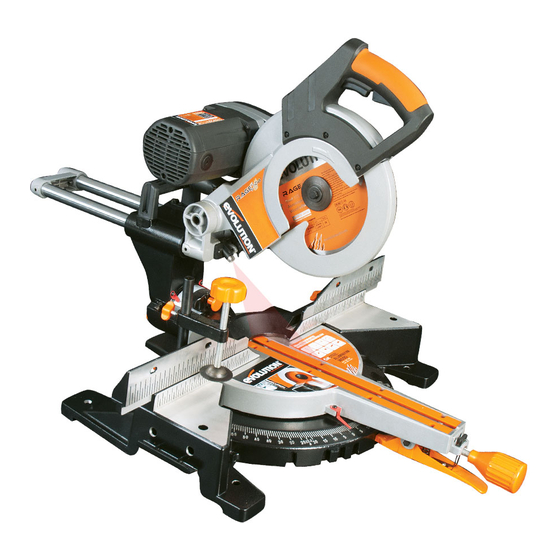
OVERALL VIEW OF DOUBLE BEVEL MITRE SAW (10) 1. ON/OFF TRIGGER SWITCH 6. ROTARY TABLE 2. BLADE GUARD LOCKING TRIGGER 7. LOWER BLADE GUARD 3. CUTTING HANDLE 8. UPPER BLADE GUARD 4. DUST BAG (Optional Accessory) 9. BLADE 5. TABLE TOP 10. - Page 13 OVERALL VIEW OF DOUBLE BEVEL MITRE SAW (17) (15) (20) (19) (11) (14) (12) (14) (13) (18) (16) 11. SLIDE LOCKING SCREW 17. MOTOR COVER 12. BEVEL ANGLE SCALE 18. MITRE ANGLE SCALE 13. POSITIVE STOP LOCKING LEVER 19. RETAINING CLIP 14.
-
Page 14: Assembly And Preparation
ASSEMBLY AND PREPARATION WARNING: Always disconnect the saw from the power source before making any adjustments. NOTE: It is recommended that all instructions are always read before operating. PERMANENTLY MOUNTING THE MITRE SAW To reduce the risk of injury from unexpected saw movement, place the saw in the desired location either on a workbench or other suitable machine stand. - Page 15 • Never exchange the laser module assembly for a different type or class of laser. • Repairs to the laser module must only be conducted by Evolution Power Tools or their authorized agent. www.evolutionpowertools.com...
- Page 16 LASER ADJUSTMENT WARNING: At no time during this procedure should the motor be started. To check laser alignment: • Place a piece of cardboard, or similar, onto the rotary table of the machine. • With the carriage slide in the rearmost position, lower the Cutting Head so that a blade tooth makes a mark in the cardboard.
- Page 17 NOTE: The following WARNING labels may be • Switch on the laser beam. found on this machine: • Position the workpiece on the rotary table and against the fence. • Slide the workpiece into position until LASER RADIATION DO NOT STARE INTO THE BEAM the pencil line on the workpiece and the CLASS 2 LASER PRODUCT...
- Page 18 DEPTH STOP (Fig. 8) Use of the depth stop allows the operator to cut slots in the workpiece. The downward travel of the Cutting Head can be set so that the saw blade does not completely cut through the workpiece. NOTE: When using the Depth Stop it is advisable that the depth of cut is checked using a scrap piece of timber to ensure that the slot cut is correct.
-
Page 19: Operating Instructions
OPERATING INSTRUCTIONS • Secure the workpiece firmly to the table and against the fence to prevent CAUTION: The Mitre Saw should be inspected any movement. (particularly for the correct functioning of • Use a Hold Down Clamp if possible but the safety guards) before each use. - Page 20 BEVEL ANGLES (0 AND 45 Bevel Stop Adjustment • Ensure that the Cutting Head is in the locked down position with the latching pin fully engaged in its socket. (see Fig. A pg 11) • Ensure that the Cutting Head is upright, against its stop and the bevel pointer is indicating 0 on the scale.
- Page 21 • Loosen the locknut on the 45 Bevel Adjustment Screw. • Use a Hex Key to adjust the Adjustment Screw in or out as required. (Fig. 15) • Tilt the Cutting Head to the 45 setting and recheck for alignment with the Set Square. •...
- Page 22 FENCE ALIGNMENT The fence must be aligned at 90 (square) to a correctly installed blade The rotary table must be set at ‘0 ’ miter angle. The Fence is fastened to the table with two socket head Hex screws positioned at either side of the fence in elongated slots.
- Page 23 completed. Ensure that the ‘cut-off’ piece cannot become ‘jammed’ in any other part of the machine. • Do not use this saw to cut small pieces. If the workpiece being cut would cause your hand or fingers to be within 150mm of the sawblade, the workpiece is too small.
- Page 24 SLIDE CUTTING This saw is equipped with a Sliding Carriage system. Loosening the slide lock screw will release the slide and allow the Cutting Head to move forwards and backwards. (Fig. 25) The saw blade is lowered into the workpiece and then pushed to the rear of the machine to complete a cut.
- Page 25 MITRE CUTTING (Fig. 28) The rotary table of this machine can be turned through 55 to the left or right from the normal cross-cut (0 ) position. Positive stops are provided at 45 , 30 , 22.5 and 15 both the right hand and left hand sides. Mitre Cutting is possible with or without the Sliding Carriage system being deployed.
- Page 26 To tilt the Cutting Head to the left: • Loosen the bevel lock lever. (Fig. 32) • Tilt the Cutting Head to the required angle. A protractor scale is provided as an aid to setting. (Fig 33) • Tighten the bevel lock lever when the desired angle has been selected.
- Page 27 position, with the lower blade guard completely deployed before removing yours hand(s). • Return the Cutting Head to the perpendicular position. • Return the Right Hand Bevel Access Pin to its original position. • Tighten the bevel lock lever. COMPOUND CUTTING (Fig. 35) A compound cut is a combination of a mitre and bevel cut employed simultaneously.
- Page 28 INSTALLING OR REMOVING A BLADE WARNING: Only carry out this operation with the machine disconnected from the mains supply. WARNING: Only use genuine Evolution blades which are designed for this machine. Fig. 37 Ensure that the maximum speed of the blade is higher than the speed of the motor.
-
Page 29: Use Of Optional Accessories
USE OF OPTIONAL EVOLUTION ACCESSORIES Not supplied as original equipment. All accessories can be purchased from Evolution Power Tools. See ‘Additional Accessories’ section. DUST BAG A Dust Bag can be fitted to the extraction port at the Fig. - Page 30 WORKPIECE SUPPORT BARS (Fig. 43a & 43b) Workpiece Support Bars can be fitted to either or both sides of the machines base as required. • Right Hand side. Loosen the support retaining screw located in the top front of the machines base. •...
-
Page 31: Final Safety Check List
Replacement inserts (sold in handed pairs) Fig. 46 are available from your supplier or Evolution Power Tools. To replace the table inserts: • Remove the 3 or 4 cross-head screws that secure one of the inserts to the rotary table. - Page 32 Tensioning / replacing the drive belt WARNING: Only attempt these procedures with the machine disconnected from the power supply. Tensioning the belt: • To gain access to the transmission case remove the plastic case cover by unscrewing the two (2) cross head screws which hold it in place.
-
Page 33: Environmental Protection
ENVIRONMENTAL PROTECTION Information (for private householders) for the environmentally responsible disposal of Waste Electrical and Electronic Equipment (WEEE). This symbol on products, or accompanying documents, indicates that used and end of life electrical and electronic equipment should not be disposed of with household waste. For proper disposal, treatment, recovery and recycling, please take these products to designated collection points, where they will be accepted on a free of charge basis Alternatively, in some countries you may be able to return your products to your retailer upon the purchase of an... - Page 34 PARTS DIAGRAM (NON ASSEMBLY) www.evolutionpowertools.com...
-
Page 35: Your Notes
® The manufacturer of the product covered by this Declaration is: Evolution Power Tools, Venture One, Longacre Close, Holbrook Industrial Estate, Sheffield, S20 3FR The manufacturer hereby declares that the machine as detailed in this declaration fulfils all the relevant provisions of the Machinery Directive and other appropriate directives as detailed below. -
Page 36: Parts Diagrams & Ec Declaration Of Conformities
® UK HQ FRANCE HQ USA HQ Evolution Power Tools, Evolution Power Tools, Evolution Power Tools LLC, Venture One, Longacre Close, 61 Avenue Lafontaine, 33560, 8363 Research Drive, Holbrook Industrial Estate, Carbon-Blanc, Davenport,Iowa 52806 Sheffield, S20 3FR, UK France U.S.A TEL: +44 (0) 114 251 1022 TÉL: + 33 (0)5 57 30 61 89...
Need help?
Do you have a question about the RAGE3-DB and is the answer not in the manual?
Questions and answers