
Related Manuals for Evolution RAGE 5


Summary of Contents for Evolution RAGE 5
- Page 1 RAGE 5 Original Instructions Written in UK English Date Published: 15 / 08 / 2013...
-
Page 2: Table Of Contents
www.evolutionpowertools.com TABLE OF CONTENTS English Page 02 Deutsch Seite 32 Español Página 68 Français Page 104 Italiano Pagina 140 Nederlands Pagina 176 Important Information Page 03 Guarantee Page 03 Specification Page 04 Labels & Symbols Page 05 General Safety Rules Page 06 Safety Precautions for All Saws Page 06... -
Page 3: Important Information
You can also scan the or paddles etc. In no event shall Evolution QR code found on the A4 leaflet with Power Tools be liable for loss or damage a Smart Phone. -
Page 4: Specification
www.evolutionpowertools.com SPECIFICATIONS MACHINE METRIC IMPERIAL Motor UK/EU: 230-240V ~ 50Hz (S6 40%) 1800W Motor UK: 110V ~ 50Hz 1600W Table Dimensions 656 x 1260mm 26 x 49-5/8” Speed (No Load) 2500min 2500rpm CUTTING CAPACITIES Mild Steel Plate – Max Thickness 1/4”... -
Page 5: Labels & Symbols
LABELS & SYMBOLS WARNING: Do not operate the saw if any Symbol Description warning and/or instruction labels are missing or damaged. Contact evolution power tools for Volts replacement labels. Only use genuine Evolution replacement Amperes blades. Unauthorized blades may be dangerous! Keep the blades securely fastened. -
Page 6: General Safety Rules
www.evolutionpowertools.com IMPORTANT SAFETY INSTRUCTIONS c) Keep children and bystanders away while operating a power tool. To reduce the risk of electric shock, this equipment is fitted with an approved cord and Distractions can cause you to lose control. plug for its intended country of use. Do not change the cord or plug in any way. - Page 7 www.evolutionpowertools.com dust mask, non-skid safety shoes, hard hat, Power tools are dangerous in the hands of or hearing protection used for appropriate untrained users. e) Maintain power tools. Check for conditions will reduce personal injuries. misalignment or binding of moving parts, c) Avoid accidental starting.
-
Page 8: Additional Specific Safety Rules
Wearing gloves when handling saw blades or knife regularly and replace it if it is worn. Use rough material. only a genuine Evolution riving knife as this is a f) Saw blades should be carried in a holder dedicated component for this machine. - Page 9 Mitre Gauge o) Use recommended accessories. Only use Assembly genuine Evolution accessories. p) Check for damaged parts. Before further use of the tool, a guard or other part that Hold Down Clamp is damaged should be carefully checked to...
-
Page 10: Machine Overview
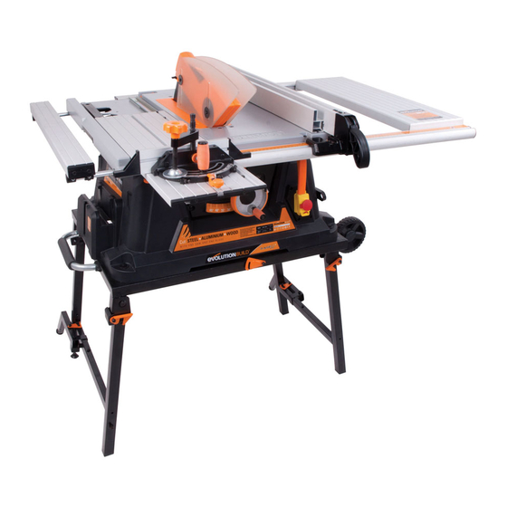
MACHINE OVERVIEW OF EVOLUTION 255mm (10˝) RAGE TABLE SAW Know your parts 1. On/Off Switch 2. Sliding Carriage 3. Mitre Gauge 4. Blade Guard 5. Rip Fence 6. Rip Fence Locking Handle 7. Transportation Handle 8. Transportation Wheels 9. Hold Down Clamp 10. -
Page 11: Service Parts Diagram
www.evolutionpowertools.com PARTS DIAGRAM Parts Diagrams can also be downloaded from www.evolutionpowertools.com... - Page 12 www.evolutionpowertools.com PARTS DIAGRAM Parts Diagrams can also be downloaded from www.evolutionpowertools.com...
-
Page 13: Assembly
www.evolutionpowertools.com ASSEMBLY & OPERATION Note: Some minor assembly is required to prepare this machine for use. Please refer to the Service Parts Diagram. Some of the following tasks can be carried out with the machine still in its packaging if desired. WARNING : Do not connect this machine to a power supply until assembly has been completed, and a thorough safety check of the... - Page 14 www.evolutionpowertools.com ASSEMBLY & OPERATION 2. Fitting the Riving Knife WARNING: Ensure that this procedure is only carried out with the machine disconnected from the mains supply. The Riving Knife is a very important component, and must be fitted correctly. The Riving Knife has two functions: •...
- Page 15 www.evolutionpowertools.com ASSEMBLY & OPERATION To attach the assembled Rip Fence to the machine: • Hook the rear of the Rip Fence Guide over the rear Rip Fence Rail. (Fig. 6A) • With the handle in its upper position, locate the front of the Rip Fence over the front Rip Fence Rail.
-
Page 16: Operation
www.evolutionpowertools.com ASSEMBLY & OPERATION • Check the operation of the blade guard. Ensure that it is working efficiently and covers the blade entirely at the sides as well as the crown. • Lower the blade a little and recheck that the blade guard operation. - Page 17 www.evolutionpowertools.com ASSEMBLY & OPERATION 2. Raising/Lowering the blade WARNING : Only make adjustments to the machine when the machine is switched OFF and the blade is stationary. Note: This machine is equipped with a dual function folding handle hand-wheel. In its ‘normal’ (outer) position the hand- wheel is used to raise or lower the blade.
- Page 18 www.evolutionpowertools.com ASSEMBLY & OPERATION 4. Rip Fence Guide This machine is fitted with a two piece Rip Fence. We recommend that the Rip Fence is normally used in conjunction with its adjustable Face piece. The Rip Fence should be positioned to the RH side of the blade and is locked in position by using the locking lever.
- Page 19 www.evolutionpowertools.com ASSEMBLY & OPERATION To reposition the Rip Fence Face: • Loosen the two thumb nuts to the RH side of the Rip Fence. • Slide out the Rip Fence Face extrusion. • Re-attach the Rip Fence Face in the ‘Lo’ position. •...
- Page 20 www.evolutionpowertools.com ASSEMBLY & OPERATION Note: Each of the fast index screws has been factory set for angular accuracy. All the index screws can be adjusted if necessary. The ‘stop plate’ should rotate easily. It is important that the punched swage on the plate (Fig. 21) which prevents it from being over-rotated and potentially fouling the ‘T’...
- Page 21 www.evolutionpowertools.com ASSEMBLY & OPERATION To Check 45 Settings • Raise the blade to its full height. • Place the 45 square on the machine table with one face resting accurately against the saw blades body. (Fig. 25) • Check that the Mitre Gauge is set at one of the 45 settings.
- Page 22 www.evolutionpowertools.com ASSEMBLY & OPERATION Sliding Carriage System This machine is fitted with a Sliding Carriage to the LH side of the blade. This facility can be particularly useful when cross- cutting small section material such as metal box-section or extrusions etc. The sliding carriage should always be used with the Mitre Gauge locked to it in the desired position.
- Page 23 ASSEMBLY & OPERATION BASIC TABLE SAW OPERATIONS Multi-purpose blade The Rage 5 comes fitted with a multi-purpose TCT blade which is capable of cutting many materials. We recommend that a workshop dust extraction system is always attached to the dust extraction port (Fig. 30) when cutting wood or wooden products to prevent any possible build up of sawdust in the lower blade guard.
- Page 24 www.evolutionpowertools.com ASSEMBLY & OPERATION 3. Bevel crosscutting Bevel crosscutting is the same as crosscutting but with the blade tilted at an angle. Tilt the blade to the desired angle as previously described, and ensure that it is locked in place. Set the mitre gauge to 90 and adjust the faceplate so that it does not touch or foul the saw blade as it passes.
- Page 25 www.evolutionpowertools.com ASSEMBLY & OPERATION 6. Rip cutting Rip cutting is cutting along the length of a piece of material rather than across it. Rip cutting should always be done with the Rip Fence Face set to the desired width and on the RH side of the machines table.
- Page 26 www.evolutionpowertools.com ASSEMBLY & OPERATION Note: Although the Mitre Gauge can be locked in any desired position along the ‘T’ slot it does have a dedicated position to the front of the carriage, where the locking screw will engage in a hole in the sliding carriage body. (Fig. 38) •...
- Page 27 www.evolutionpowertools.com ASSEMBLY & OPERATION WARNING: Ensure that the machine is disconnected from the mains supply before any maintenance tasks or adjustments are attempted. CHANGING THE BLADE Note: We recommend that the operator considers wearing protective gloves when handling or changing the machines blade. 1.
-
Page 28: Maintenance
MAINTENANCE Note: Use only a genuine Evolution Riving Knife, as this is a dedicated component for this machine. Non genuine parts could be dangerous. If in any doubt, please contact the Helpline. Push Stick A plastic push stick is provided with the machine and has its own dedicated storage brackets to the RH side of the machines main body. -
Page 29: Environmental Protection
www.evolutionpowertools.com ENVIRONMENTAL PROTECTION Waste electrical products should not be disposed of with household waste. Please recycle where facilities exist. Check with your Local Authority or retailer for recycling advice. TROUBLE SHOOTING GUIDE CONDITION POSSIBLE CAUSE ACTION Machine will not start. Plug removed from outlet Replace plug and/or switch socket or outlet socket... -
Page 30: Ec Declaration Of Conformity
In accordance with EN ISO 17050-1:2004 The manufacturer of the product covered by this Declaration is: Evolution Power Tools, Venture One, Longacre Close, Holbrook Industrial Estate, Sheffield, S20 3FR The manufacturer hereby declares that the machine as detailed in this declaration fulfils all the relevant provisions of the Machinery Directive and other appropriate directives as detailed below. - Page 31 www.evolutionpowertools.com NOTES...
- Page 32 Evolution Power Tools Ltd Evolution Power Tools LLC Venture One 8363 Research Drive Longacre Close Davenport Holbrook Industrial Estate Iowa Sheffield 52806 S20 3FR +44 (0)114 251 1022 866-EVO-TOOL エボリューション Evolution Power Tools Ltd パワーツール株式会社 61 Avenue Lafontaine 〒544-0031 33560 大阪府大阪市生野区...
Need help?
Do you have a question about the RAGE 5 and is the answer not in the manual?
Questions and answers