Evolution Rage3-db Original Instructions Manual
255mm (10”) double level tct multipurpose sliding mitersaws
Hide thumbs
Also See for Rage3-db:
- Original instruction manual (36 pages) ,
- Original instructions manual (116 pages)

Related Manuals for Evolution Rage3-db


Summary of Contents for Evolution Rage3-db
- Page 1 Original Instructions Written in UK English Date Published: 01 / 03 / 2014...
- Page 3 ENGLISH Original Instructions...
-
Page 4: Table Of Contents
www.evolutionpowertools.com TABLE OF CONTENTS* English Page 02 Español Página 38 Français Page 76 MAChiNE SpECiFiCATiON Introduction Guarantee Vibration Intended use of this Power Tool Prohibited use of this Power Tool SAFETY pRECAUTiONS Electrical Safety General Power Tool Safety Instructions Health Advice Specific Safety Instructions Personal Protective Equipment (PPE) Safe Operation... -
Page 5: Machine Specification
www.evolutionpowertools.com 255mm (10”) DOUBLE BEVEL TCT MULTIpUrpOSE SLIDING MITrE SawS MAChiNE SpECiFiCATiONS METRiC iMpERiAL Motor UK (230V ~ 50/60 Hz) 2000W Motor UK (110V ~ 50/60 Hz) 1600W Motor USA (120V ~ 60 Hz) 1800W No Load Speed 2500min 2500rpm Weight N: 19.6kg / G: 21kg N: 43lb / G: 46lb... -
Page 6: Introduction
You can also scan the or paddles etc. In no event shall Evolution QR code found on the A4 leaflet with Power Tools be liable for loss or damage a Smart phone. -
Page 7: Vibration
/ or instruction labels are missing of vibration transmitted to the hand and or damaged. Contact Evolution Power Tools for arm. it is possible that the operator could replacement labels. develop “Vibration white finger disease”... -
Page 8: Prohibited Use Of This Power Tool
www.evolutionpowertools.com When fitted with a correct blade this machine can be used to cut: Wood Wood derived products (MDF, Chipboard, Plywood, Blockboard, Hardboard etc) Aluminium Mild Steel (6mm Ø) NOTE: Wood containing non galvanised nails or screws can, with care, be safely cut. pROhiBiTED USE OF ThiS pOWER TOOL If for any reason the 13 amp moulded plug... -
Page 9: General Power Tool Safety Instructions
www.evolutionpowertools.com OUTDOOR USE 2) General power Tool Safety Warnings [Electrical Safety] • Power tool plugs must match the outlet. WARNiNG: For your protection if this tool is to Never modify the plug in any way. Do be used outdoors it should not be exposed to not use any adapter plugs with earthed rain, or used in damp locations. -
Page 10: Health Advice
www.evolutionpowertools.com • Prevent unintentional starting. Ensure untrained users. the switch is in the off-position before • Maintain power tools. Check for connecting to power source and or misalignment or binding of moving parts, battery pack, picking up or carrying the breakage of moving parts and any other tool. -
Page 11: Specific Safety Instructions
www.evolutionpowertools.com MiTRE SAW SpECiFiC SAFETY Gloves should be worn when handling blades or rough material. It is recommended that saw blades should be carried in a holder wherever The following specific safety instructions for practicable. It is not advisable to wear gloves Mitre Saws are based on the requirements of when operating the mitre saw. -
Page 12: Aditional Safety Advice
www.evolutionpowertools.com The saw blade shall only be replaced as back. Lift by using the handhold areas at each side of the machines base. detailed in this Instruction Manual. • Never carry the Mitre Saw by the power Never attempt to retrieve off-cuts or any other cord. -
Page 13: Additional Accessories
Dust Collection Bag EV3DBS202 Workpiece Support Bars EV3DBS76 End Stop EV3DBSM3 Step 3 (Repetitive Cutting) Additional accessories and information on the use and type of accessory suitable for your machine can be obtained by contacting your local dealer (or Evolution Power Tools). -
Page 14: Machine Overview
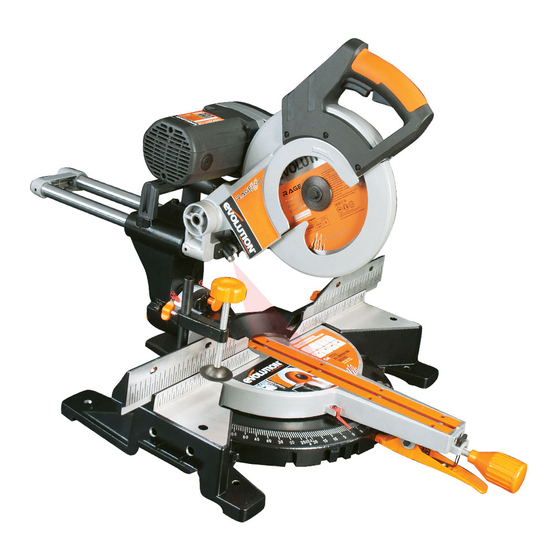
www.evolutionpowertools.com OVERALL ViEW OF DOUBLE BEVEL MiTRE SAW 1. ON/OFF TRIGGER SWITCH 6. ROTARY TABLE 2. BLADE GUARD LOCKING TRIGGER 7. LOWER BLADE GUARD 3. CUTTING HANDLE 8. UPPER BLADE GUARD 4. DUST BAG (Optional Accessory) 9. BLADE 5. TABLE TOP 10. - Page 15 www.evolutionpowertools.com OVERALL ViEW OF DOUBLE BEVEL MiTRE SAW 11. SLIDE LOCKING SCREW 17. MOTOR COVER 12. BEVEL ANGLE SCALE 18. MITRE ANGLE SCALE 13. POSITIVE STOP LOCKING LEVER 19. RETAINING CLIP 14. FENCE 20. ARBOR LOCK 15. HEAD LATCHING PIN 21.
-
Page 16: Assembly And Preparation
www.evolutionpowertools.com ASSEMBLY AND pREpARATiON WARNiNG: Always disconnect the saw from the power source before making any adjustments. NOTE: It is recommended that all instructions are always read before operating. pERMANENTLY MOUNTiNG ThE MiTRE SAW To reduce the risk of injury from unexpected saw movement, Fig. - Page 17 Please observe all of the following safety rules. • The laser beam must not be deliberately aimed at personnel and must be prevented from being directed towards the eyes of a person. • Always ensure that the laser beam is used only on workpieces that have non-reflective surfaces, i.e natural wood or matt surfaces etc. • Never exchange the laser module assembly for a different type or class of laser. • Repairs to the laser module must only be conducted by Evolution Power Tools or their authorized agent.
- Page 18 www.evolutionpowertools.com LASER ADJUSTMENT WARNiNG: At no time during this procedure should the motor be started. To check laser alignment: • Place a piece of cardboard, or similar, onto the rotary table of the machine. • With the carriage slide in the rearmost position, lower the Cutting Head so that a blade tooth makes a mark in the cardboard. • Allow the Cutting Head to rise, and then repeat the above Fig. 6 with the carriage slide in an approximate mid- way position.
- Page 19 www.evolutionpowertools.com NOTE: The following WARNiNG labels may be found on this machine: LASER RADiATiON DO NOT STARE iNTO ThE BEAM CLASS 2 LASER pRODUCT CLASS 2 LASER pRODUCT LASER RADiATiON AVOiD DiRECT EYE CONTACT LASER SAFETY The Laser guide line used in this product uses a class II Laser with a maximum power output of 1.5mW at a wave length of between 635 and 670nm.
- Page 20 www.evolutionpowertools.com To use the laser guide for an unknown angle: • Mark the position of the cut to be made on the workpiece using a pencil etc. • Place the workpiece on the rotary table and against the fence. • Adjust the mitre saw to give the approximate angle of cut. Do not tighten the mitre lock handle at this stage.
-
Page 21: Operating Instructions
www.evolutionpowertools.com • When cutting is complete re-adjust the depth stop so that the Cutting Head can be locked in the down position by the head latching pin. ThE SLiDiNG UppER FENCE SECTiON The Left Hand and Right Hand sides of the Fence have an adjustable upper section. Adjustment may be necessary to provide clearance for the moving Cutting Head when acute bevel or compound angles are selected. - Page 22 www.evolutionpowertools.com BODY AND hAND pOSiTiONiNG ADJUSTMENT OF pRECiSiON ANGLES (Fig. 10) • Never place your hands within the ‘no hands Several checks/adjustments are possible on zone’ (at least 150mm away from the blade). this machine. The operator will require a 90 Keep hands away from the path of the blade. Set Square (not supplied) to carry out • Secure the workpiece firmly to the table and these checks and adjustments.
- Page 23 www.evolutionpowertools.com BEVEL ANGLES (0 AND 45 Bevel Stop Adjustment • Ensure that the Cutting Head is in the locked down position with the latching pin fully engaged in its socket. (see Fig. A pg 11) • Ensure that the Cutting Head is upright, against its stop and on the scale. (Fig. 11) the bevel pointer is indicating 0 • Loosen Bevel Lock Handle. • Place the Engineers Square on the table with one edge Fig.
- Page 24 www.evolutionpowertools.com Bevel pointer Adjustment NOTE: The operator must be satisfied that the blade is set exactly perpendicular to the table when in the upright position and against its stop. • If the pointer is not in exact alignment with the 0 mark on the protractor scale adjustment is necessary. • Loosen the Bevel Pointer screw using a #2 Phillips screwdriver.
-
Page 25: Fence Alignment
www.evolutionpowertools.com • Tilt the Cutting Head to the 45 setting and recheck for alignment with the Set Square. • Repeat the above steps until the correct angular alignment is achieved. • Tighten the Adjustment Screw locknut securely once alignment is achieved. FENCE ALiGNMENT The fence must be aligned at 90 (square) to a correctly installed blade The rotary table must be set at ‘0 ’... -
Page 26: Chop Cutting
www.evolutionpowertools.com pREpARiNG TO MAKE A CUT DO NOT OVER-REACh Keep good footing and balance. Stand to one side so that your face and body are out of line of a possible kickback. FREEhAND CUTTiNG iS A MAJOR CAUSE OF ACCiDENTS AND MUST NOT BE ATTEMpTED. -
Page 27: Slide Cutting
www.evolutionpowertools.com The Lower Guard Locking Trigger (Fig. 25) • Lower the Cutting Handle downwards and cut through the workpiece. • Allow the speed of the blade to do the work, there is no need to apply undue pressure to the Cutting Handle. • When the cut has been completed, release the ON/OFF trigger switch. • Allow the blade to come to a complete stop. • Allow the Cutting Head to rise to its upper position, with the lower blade guard completely covering the blade teeth, Fig. - Page 28 www.evolutionpowertools.com WARNiNG: Never pull the Cutting Head and spinning blade towards you when making a sliding cut. The blade may try to climb up on top of the workpiece, causing the Cutting Head to ‘Kickback’ forcefully. The Cutting Head should always be positioned as outlined above before attempting to make a sliding cut.
- Page 29 www.evolutionpowertools.com BEVEL CUTTiNG - TiLTiNG ThE CUTTiNG hEAD A bevel cut (Fig. 32) is made with the rotary table set at 0 mitre. NOTE: It may be necessary to adjust the upper section of the Fence to provide clearance for the moving Cutting Head. The Cutting Head can be tilted from the normal 0 (perpendicular position) to a maximum angle of 45...
- Page 30 www.evolutionpowertools.com When cutting is completed: • Release the ON/OFF trigger switch, but keep your hands in position and allow the blade to completely stop. • Allow the Cutting Head has to rise to its upper position, with the lower blade guard completely deployed before removing yours hand(s). • Return the Cutting Head to the perpendicular position. • Return the Right Hand Bevel Access Pin to its original position. • Tighten the bevel lock lever. Fig.
- Page 31 WARNiNG: Only carry out this operation with the machine disconnected from the mains supply. Fig. 38 WARNiNG: Only use genuine Evolution blades which are designed for this machine. Ensure that the maximum speed of the blade is higher than the speed of the motor.
-
Page 32: Use Of Additional Accessories
If required, Blade Bore Reducing Inserts should only be used in accordance with the manufacturers instructions. USE OF OpTiONAL EVOLUTiON ACCESSORiES Not supplied as original equipment. All accessories can be purchased from Evolution power Tools. See ‘Additional Accessories’ section. DUST BAG Fig. 43 A Dust Bag can be fitted to the extraction port at the rear of the machine. - Page 33 www.evolutionpowertools.com EXTRACTiON pORT ADApTOR TUBE Use the Adaptor Tube to connect the extraction port of the machine to suitable commercial workshop vacum extraction equipment (not supplied) which have Ø30mm internal bore hoses or inlet ports. WORKpiECE SUppORT BARS (Fig. 44a & 44b) Workpiece Support Bars can be fitted to either or both sides of the machines base as required.
-
Page 34: Maintenance
Table insert A two piece table insert is fitted to this machine. If either side is damaged or worn, both parts must be replaced. Replacement inserts (sold in handed pairs) are available from your supplier or Evolution Power Tools. - Page 35 www.evolutionpowertools.com To replace the table inserts: • Remove the 3 or 4 cross-head screws that secure one of the inserts to the rotary table. • Lift the insert from the table. • Remove any debris that may have accumulated under the insert. • Fit the replacement insert, and replace the three fixing screws. • Repeat the process for the other side. • Check that all 6 or 8 fixing screws are tightened securely, and that both inserts are lying flush and level within the table. Tensioning / replacing the drive belt Fig. 46 WARNiNG: Only attempt these procedures with the machine disconnected from the power supply.
-
Page 36: Environmental Protection
www.evolutionpowertools.com ENViRONMENTAL pROTECTiON information (for private householders) for the environmentally responsible disposal of Waste Electrical and Electronic Equipment (WEEE). This symbol on products, or accompanying documents, indicates that used and end of life electrical and electronic equipment should not be disposed of with household waste. For proper disposal, treatment, recovery and recycling, please take these products to designated collection points, where they will be accepted on a free of charge basis Alternatively,... -
Page 37: Ec Declaration Of Conformities
EC DECLARATiON OF CONFORMiTY The manufacturer of the product covered by this Declaration is: Evolution Power Tools, Venture One, Longacre Close, Holbrook Industrial Estate, Sheffield, S20 3FR. The manufacturer hereby declares that the machine as detailed in this declaration fulfils all the relevant provisions of the Machinery Directive and other appropriate directives as detailed below. - Page 38 Evolution Power Tools Ltd Evolution Power Tools LLC Evolution Power Tools SAS Venture One, Longacre Close 8363 Research Drive 61 Avenue Lafontaine Holbrook Industrial Estate Davenport 33560 Sheffield Iowa Carbon-Blanc S20 3FR 52806 Bordeaux +44 (0)114 251 1022 +1 866-EVO-TOOL...
Need help?
Do you have a question about the Rage3-db and is the answer not in the manual?
Questions and answers