Table of Contents
Advertisement
Advertisement
Table of Contents

Related Manuals for 2N VoiceBlue Lite


Summary of Contents for 2N VoiceBlue Lite
- Page 1 2N - VoiceBlue Lite User Manual Version: 2.3...
- Page 2 Dear customer, let us congratulate you on having purchased the 2N – VoiceBlue Lite system. This new product has been developed and produced in order to provide the maximum utility value, quality and reliability to the user. We hope you will be fully satisfied with our 2N –...
-
Page 3: Packing List
- VoiceBlue Lite delivery for compliance with the following packing list. Item Pieces 2N - VoiceBlue Lite – check the model type according to the order number, see the type label on the gateway back side Mains adapter according to type... -
Page 5: Table Of Contents
GSM Indicators..................18 2.10. Lithium Battery Replacement..............20 2.11. Fuse Replacement ..................22 2.12. Antenna Splitter ..................22 SECTION 3 – 2N - VOICEBLUE LITE INSTALLATION ....23 3.1. Proper Installation Conditions ..............24 3.2. VoiceBlue Lite Installation..............24 3.3. Potential GSM Network Problems ............25 SECTION 4 – VOICEBLUE LITE CONNECTION TO VOIP ...27 4.1. - Page 6 SECTION 6 – 2N - VOICEBLUE LITE ROUTING RULES ....37 6.1. Functions Supported by 2N – VoiceBlue Lite ........38 6.2. Call Routing Rules .................. 38 6.3. LCR table....................38 6.4. Call Routing to GSM via VoiceBlue Lite ..........39 6.5.
- Page 7 Autorouting Table ................74 8.6. On-line Information on GSM Modules ...........76 Diagnostics..................76 Actual calls..................78 8.7. Reset......................78 8.8. Select Gateway ..................78 8.9. Communication Setting ................78 SECTION 9– CONFIGURATION OF EXTERNAL CALLBACK ..80 9.1. Introduction to the External Routing Software........81 9.2. Installation and configuration of XAPI server.........81 9.3.
- Page 9 Figures Fig. 1 – Bottom View....................8 Fig. 2 – Top View ....................9 Fig. 3 – Gateway Holder Wall-Mounting ..............11 Fig. 4 – Gateway Hanging ..................11 Fig. 5 – Direct PC Connection Using USB............13 Fig. 6 – Direct PC Connection Using RS232 ............14 Fig.
- Page 10 Fig. 37 – Outgoing Group Setting Window............66 Fig. 38 – Incoming Group Setting Window ............69 Fig. 39 – GSM Calling Group Defining Window ..........72 Fig. 40 – LCR table ....................73 Fig. 41 – LCR table Completion................73 Fig. 42 - Autorouting table ..................75 Fig.
-
Page 13: Section 1 - Product Presentation
2N - VoiceBlue Lite S E C T I O N 1 – Product Presentation Here is a survey of what you will find in this section: • Purpose • How to Cut Telephone Costs • Other Advantages and Applications... -
Page 14: Purpose
GSM and VoIP parameters. 1.2. How to Cut Telephone Costs • Once you connect the 2N – VoiceBlue Lite gateway to your VoIP PBX, you can make all outgoing calls to a mobile network directly. Thus, you cut your PSTN - mobile network call costs. -
Page 15: Other Advantages And Applications
GSM gateway SIM cards. 1.3. Other Advantages and Applications • 2N - VoiceBlue Lite integrates the best of the GSM and VoIP communication technologies. • The GSM gateway keeps detailed statistics on incoming and outgoing calls. -
Page 16: Rf Radiation Safety Precautions
1.4. RF Radiation Safety Precautions It is prohibited to use any transmitters, including VoiceBlue Lite, in areas where explosives are used, such as quarries. It is forbidden to use mobile phones and thus VoiceBlue Lite too at refuelling points. A GSM gateway may affect sensitive life-saving devices in medical centres. -
Page 17: Section 2 - Installation
S E C T I O N 2 – Installation This section deals mainly with the proper mounting of the 2N - VoiceBlue Lite and its connectors. One subsection is devoted to the lithium battery replacement. Here is a survey of what you will can in this section: •... -
Page 18: Get Started
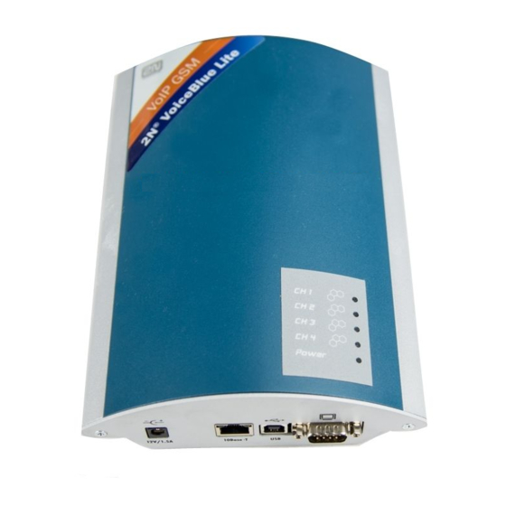
• Fuse Replacement • Antenna Splitter 2.1. Get Started Before you start installing your VoiceBlue Lite gateway, get familiar with its physical structure, arrangement of connectors and status indicators; see Fig. 1, Fig. 2, and Fig. 12. Fig. 1 – Bottom View... -
Page 19: Brief Installation Guide
Fig. 2 – Top View 2.2. Brief Installation Guide • Proper mounting – 2N – VoiceBlue Lite is designed for suspension on a vertical surface. Fit the holder included in the delivery on a wall and hang the gateway on it. For details on the prescribed working position and other recommendations refer to Subs. - Page 20 • PC connection – the gateway parameters are normally set using the configuration software available on the CD included in the delivery. To interconnect your PC with 2N - VoiceBlue Lite use the USB cable or laplink RS 232 cable included in the delivery.
-
Page 21: Proper Mounting
2N - VoiceBlue Lite 2.3. Proper Mounting • The 2N - VoiceBlue Lite gateway is designed for mounting on a vertical surface. For this purpose a wall- mounting holder is available. Just fit the holder with dowels and screws (Fig. 3) to the wall and hang the gateway as shown in (Fig. -
Page 22: Pc Or Lan Connection
2.4. PC or LAN Connection The 2N - VoiceBlue Lite gateway can be connected to a PC using a USB cable terminated with a USB B connector or a laplink serial cable with RS 232 connectors. A direct connection of... -
Page 23: Fig. 5 - Direct Pc Connection Using Usb
2N - VoiceBlue Lite Windows 98SE/ME/2000/XP OS. While installing the drivers please following the instructions below: • Insert the included CD into your PC CD-ROM drive. • Connect the USB cable to the PC and then to VoiceBlue Lite. • The Windows recognises... -
Page 24: Fig. 6 - Direct Pc Connection Using Rs232
Fig. 6 – Direct PC Connection Using RS232 A standard straight through cable terminated with RJ-45 connectors is sued for connection to the 10BASE-T (Twisted Pair Ethernet) LAN (Fig. 7 and Fig. 8). Fig. 7 – LAN Connection Fig. 8 – RJ-45 Wiring for LAN Connection... -
Page 25: Antenna Connection
2N - VoiceBlue Lite 2.5. Antenna Connection The VoiceBlue Lite gateway has one SMA antenna connector for all GSM modules, see Fig. 9. An external antenna cable is connected to this connector. The external antenna should be installed vertically on a place with a good GSM signal. For the technical parameters of the antenna refer to Section 11. -
Page 26: Sim Card Installation/Removal
Fig. 10 – Supply Adapter Connection 2.7. SIM Card Installation/Removal Insert the SIM card into the SIM card slots with your hand as shown in Fig. 11. Please make sure that the slashed SIM card side is on a side opposite to the latch. Having inserted the SIM card, push the card gently until you hear a click signalling that the push/pull holders have snapped the card. -
Page 27: Pin Entering Disable (Optional)
SIM card re-insertion. 2.8. PIN Entering Disable (Optional) 2N - VoiceBlue Lite is set at automatic PIN entering by default (1234). To disable the PIN use any mobile telephone in which you insert the given SIM card. By disabling the PIN entering you invalidate any other VoiceBlue Lite parameters or PIN stored in the gateway memory. -
Page 28: Power Indicator
Each test step is signalled by a specific colour combination of the LEDs. If a test step fails, the indicator combination related to the failed test remains lighted. Power Indicator The Power LED signals whether the VoiceBlue Lite gateway is supplied or not. Power indicator (blue) Power... - Page 29 2N - VoiceBlue Lite module or a SIM card is absent, the red LED remains lighted. If a GSM module is not supplied, the respective GSM LED is blinking red. Upon a correct GSM module initialisation, the SIM card is logged in, which is signalled by a quickly blinking green LED.
-
Page 30: Lithium Battery Replacement
A survey of GSM module status signalling is included in Tab. 2. GSM Indicators GSM 1 to GSM 4 LED Colour/Status The module is ready No light Call establishing Green / shining Currently made call Green / shining Module initialisation Green / blinking slowly 1:3 SIM card initialisation Green / blinking quickly 1:1... -
Page 31: Fig. 13 - Motherboard Diagram
To replace the lithium battery, first disconnect your VoiceBlue Lite gateway from the mains and open the cover. Remove the old battery from the holder using a suitable tool and install a new one. We recommend you to have this service done by a 2N servicing centre. -
Page 32: Fuse Replacement
2.12. Antenna Splitter The antenna splitter is a passive component that enables several GSM channels to share a single antenna. With VoiceBlue Lite it joins four antenna ports into one external antenna. This splitter saves both antenna costs and installation space. It is a passive element –... -
Page 33: Section 3 - 2N - Voiceblue Lite Installation
2N - VoiceBlue Lite S E C T I O N 3 – 2N - VoiceBlue Lite Installation This section shows how to install the VoiceBlue Lite gateway properly to avoid gateway operation troubles. This section includes: • Proper Installation Conditions •... -
Page 34: Proper Installation Conditions
• A correct VoIP connection configuration according to SIP and other VoIP recommendations. 3.2. VoiceBlue Lite Installation • Place the VoiceBlue Lite GSM gateway to an environment that meets the gateway working conditions. • It is recommended to connect the supply adapter with a battery backup (UPS) and appropriate surge protection. -
Page 35: Potential Gsm Network Problems
2N - VoiceBlue Lite 3.3. Potential GSM Network Problems The VoiceBlue Lite GSM gateway is designed for a continuous 100% load. The GSM network may cause the following problems: • The GSM module(s) cannot log in, log in slowly or log out occasionally. -
Page 37: Section 4 - Voiceblue Lite Connection To Voip
VoiceBlue Lite gateway. Since 2N - VoiceBlue Lite communicates using the SIP only, the interconnection of SIP and H.323 networks is mentioned here too. 2N - VoiceBlue Lite may be operated in the Point-to-Point or Point-to-Multipoint mode with a SIP Proxy server. -
Page 38: Sip And H.323 Network Interconnection
SIP/H.323 gateway. Therefore, 2N - VoiceBlue Lite may be implemented into the existing H.323 environment using a SIP/H.323 gateway. Fig. 14 – SIP – H.323 Network Interconnection 4.2. Point-to-Point Configuration In the Point-to-Point mode, VoiceBlue Lite can only communicate with one SIP VoIP telephone or another SIP VoIP terminal, e.g. -
Page 39: Fig. 15 - Point-To-Point Configuration With Sip Voip Telephone
Fig. 15 – Point-to-Point Configuration with SIP VoIP Telephone In the Point-to-Point mode using a VoIP gateway, all calls assigned to GSM are routed to VoiceBlue Lite by the VoIP gateway. You can either set the IP address of the opposite side as... -
Page 40: Point-To-Multipoint Configuration
VoIP network. In this mode you can use multiple source terminals (e.g. VoIP telephones) and multiple destination terminals (e.g. VoiceBlue Lite). An internal routing algorithm (LCR) of your SIP Proxy is used for routing calls to GSM and other networks. -
Page 41: Section 5 - Ip Voice Transmission
2N - VoiceBlue Lite S E C T I O N 5 – IP Voice Transmission This section explains voice coding in IP networks. Moreover, essential facts are mentioned on establishing connection between two SIP-based IP telephones. This section includes: •... -
Page 42: Speech Coding Methods
Multiple the above mentioned rate by eight (four full duplex calls) and add the transmission rate ® necessary for the TCP and IP header to the resultant value for to get a successful 2N - VoiceBlue Lite Lite connection. - Page 43 During call establishing, a codec is selected automatically for voice transmission. 2N - VoiceBlue Lite is ready to use any of the codecs included in Tab. 3. The type of coding depends on your VoIP network (terminals) and VoiceBlue Lite GSM gateway configuration.
-
Page 44: Sip Components
The 2N - VoiceBlue Lite gateway is always a UA (has the same functions as a VoIP telephone), i.e. receives call requests and directs calls to GSM networks according to the internal LCR. - Page 45 2N - VoiceBlue Lite • CANCEL – termination of non-established connection; • REGISTER – UA registration in SIP Proxy; • OPTIONS – inquiry of server options. Replies to SIP messages are in the digital format like in the http protocol. Here are the most important ones: •...
- Page 46 Fig. 18 – SIP Message Sending while Connection Establishing and Terminating...
-
Page 47: Section 6 - 2N - Voiceblue Lite Routing Rules
This section explains how to set the call routing rules to make the most of the gateway potential and minimise your telephone costs. This section includes: • Functions Supported by 2N – VoiceBlue Lite • Call Routing Rules • LCR table •... -
Page 48: Functions Supported By 2N - Voiceblue Lite
6.1. Functions Supported by 2N – VoiceBlue Lite • Call routing according to time and called destination through the destination's operator; • Call re-routing; • Intelligent incoming CLIP routing (CLIP-based call routing); • Outgoing call routing by time LCR (Least Cost Routing);... -
Page 49: Call Routing To Gsm Via Voiceblue Lite
Outgoing calls are routed via VoiceBlue Lite as follows: • The calling subscriber dials a number that is routed to VoiceBlue Lite by the SIP Proxy. It depends on your SIP Proxy configuration whether or not outgoing GSM calls are routed to VoiceBlue Lite. -
Page 50: Fig. 19 - Routing Of Outgoing Gsm Calls
• If the selected GSM module is busy or has an insufficient credit, the preceding step is repeated for the following line of the Groups section. If there is no record, the next LCR table line is searched. • In case the selected GSM module is free and has a sufficiently high credit, the GSM gateway starts dialling the GSM number. -
Page 51: Incoming Calls From Gsm To Voip Network
VoIP network. Finally VoiceBlue Lite connects both calls. If callback function is enabled and calling party from GSM do not hang up till 10 s, the VoiceBlue Lite skips the callback function and tries to establish connection according to the CLIP routing table. - Page 52 To define the minimum and maximum counts of DTMF digits use the GSM incoming groups menu. • If VoiceBlue Lite does not receive the required minimum count of digits and no other digit comes from the GSM network...
-
Page 53: Fig. 20 - Incoming Call Processing Procedure
2N - VoiceBlue Lite Fig. 20 – Incoming Call Processing Procedure... -
Page 54: Disa Message
6.6. DISA Message If the DISA function is enabled and a welcome message recorded, this voice message is replayed to every incoming call whose number is not included in the CLIP routing table or dynamic CLIP routing table. After the message is replayed, the gateway waits for the first DTMF digit for a timeout defined in the GSM incoming groups –... - Page 55 2N - VoiceBlue Lite S E C T I O N 7 Introduction of Configuration Program This section introduces the 2N – VoiceBlue Lite configuration software, which is part of the installation CD supplied together with the gateway. Here is what you can find in this section: •...
-
Page 56: Voiceblue Lite Configuration Program Installation
7.1. VoiceBlue Lite Configuration Program Installation Your 2N - VoiceBlue Lite delivery includes a VoiceBlue Lite installation CD. By inserting this CD in your CD-ROM drive you get an introductory page with a survey of 2N products. Select VoiceBlue Lite and then, in a new window, VoiceBlue Lite installation. -
Page 57: Fig. 21 - Gateway Selecting Window
2N - VoiceBlue Lite Fig. 21 – Gateway Selecting Window • Add - click on Add to open a window with some essential data necessary for the gateway identification (see Fig. 22). Enter the gateway name and complete the Gateway IP address. To get the LAN connection, enter your Username and Password. - Page 58 • Edit – used for editing identification data on the gateway entered. To edit the data, select the required gateway from the list of used gateways and click on Edit. • Remove – used for removing a gateway from the list of used gateways.
-
Page 59: Fig. 23 - Gsm Program Basic Menu
2N - VoiceBlue Lite Fig. 23 – GSM Program Basic Menu... -
Page 60: Configuration Program Main Panel
Set on-line configuration Set configuration parameters On-line information on GSM modules and current calls Reset gateway Select VoiceBlue Lite for communication Set type of communication Clicking 2N – VoiceBlue Lite logo shows up basic information on VoiceBlue Lite configuration program contact information. -
Page 61: Section 8 Configuration
S E C T I O N 8 Configuration This section describes the 2N - VoiceBlue Lite gateway setting using the VoiceBlue Lite configuration software that is part of the installation CD supplied together with the gateway. Here what you can find in this section: •... -
Page 62: Establishing Communication With Voiceblue Lite
This selection opens a configuration window (see Fig. 24). You can use a serial cable, USB cable connected as a virtual COM port, the LAN or Internet for communication with VoiceBlue Lite. Fig. 24 – Communication Setting Window Types of communication:... -
Page 63: Firmware Identification And Upgrade
2N - VoiceBlue Lite serial communication mode is suitable for the initial setup of the gateway. Having set the serial communication port, define the transmission rate by clicking on Get speed. LAN communication – used for GSM gateway configuration via the Internet or LAN. -
Page 64: Firmware Uploading
(www.2n.cz). 8.3. Gateway Unlocking The operation of every new 2N - VoiceBlue Lite gateway is limited to 850 hours. Every gateway reset reduces the remaining gateway operation time by one hour. To identify the GSM gateway status, click on and select the Firmware/Lock key item. -
Page 65: On-Line Configuration Items
By inserting an invalid key you make the GSM gateway fail. 8.4. On-Line Configuration Items The items that appear when you press “CTRL” are active only if the VoiceBlue Lite gateway is connected. Login account Fig. 27 – Login Account Window... -
Page 66: Date/Time
For more details refer to Subs. 8.2. Key - if your VoiceBlue Lite gateway has been blocked for a certain number of hours, this item helps you send a key that you have received from the 2N technical support personnel to unlock the gateway. -
Page 67: Tracing
2N technical support department. If a detailed VoIP-SIP trace is required, we recommend you to connect VoiceBlue Lite using a USB cable. This type of connection allows for a detailed data transmission in every SIP report. -
Page 68: Log File
Fig. 30 – Window of Terminal Integrated in Configuration Program LOG file Used for reading and, if required, saving of LOG information from the connected VoiceBlue Lite gateway. For description of records refer to Subs. 10.7. Record on calls Reading and saving of records on calls from the connected VoiceBlue Lite gateway. -
Page 69: Statistics
8.5. Configuration Parameters Here you can modify the VoiceBlue Lite configuration even if the VoiceBlue Lite gateway is not connected. All settings are stored into a configuration file set during your gateway selection (refer to Subs. -
Page 70: Upload / Download All Parameters
Fig. 32 – Configuration File Loading and Saving Window Using this item you upload into or download from the gateway complete configuration settings of the connected VoiceBlue Lite gateway. The configuration settings may be stored in the file that you have defined during the gateway selection (refer to Subs. 7.2). -
Page 71: Ethernet Parameters
Select on which calls and whether data should be recorded in a pull-down menu. • Unit ID – used for VoiceBlue Lite identification in case in case there are more devices in the network that generate the CDR. -
Page 72: Fig. 34 - Ethernet Parameter Configuring Window
Fig. 34 – Ethernet Parameter Configuring Window • Mode/Protocol – set the signalling protocol type • Date of deleting statistics – a day in a month on which all statistical data on the VoIP interface are deleted automatically. • Voice parameters – set the voice channel parameters: •... - Page 73 VoiceBlue Lite will communicate with them. • SIP Proxy (GSM->IP) – the IP address of the SIP Proxy to which VoiceBlue Lite turns in the case of an incoming GSM call. • SIP Proxy (IP->GSM) – the IP address of the SIP Proxy from which VoiceBlue Lite awaits outgoing GSM call requests.
-
Page 74: Basic Gsm Parameters
Translation)), which is used for obtaining of public IP address presented to Internet. It is useful to fill in this field in case the VoiceBlue Lite is present in a private network behind the firewall or NAT. Default port for sending of requests on STUN is 3478. -
Page 75: Gsm Groups Assignment
• Wait for next digit – time during which VoiceBlue Lite waits for another digit dialled from the VoIP network to GSM. • Holidays list – a list of days on which VoiceBlue Lite shall route outgoing calls according to the weekend LCR table. -
Page 76: Gsm Outgoing Groups
GSM outgoing groups Fig. 37 – Outgoing Group Setting Window The 2N - VoiceBlue Lite gateway allows you to work with four groups of outgoing calls. You can select different settings for each of them with respect to establishing connections, count of called minutes and sent messages within a period. - Page 77 2N - VoiceBlue Lite • CLIR – This parameter defines whether or not the calling SIM card telephone number shall be displayed to the called party. It is not recommended to present the telephone number of the SIM card inserted in the GSM module to the called party to avoid calling back problems.
- Page 78 Example: If, from the viewpoint of the GSM provider, a call shorter than 60s is billed as a 60s call, set the Minimum call length at 60s. If the GSM provider bills calls in seconds after the first 60s, set the Call length measurement accuracy at 1 s.
-
Page 79: Gsm Incoming Groups
GSM incoming groups Fig. 38 – Incoming Group Setting Window The 2N - VoiceBlue Lite gateway allows you to work with four groups of incoming calls. You can select different settings for each of them with respect to establishing incoming calls. To set the default parameters use the Default button. - Page 80 • Receive incoming calls + voice message – incoming calls from the GSM network are received and, if defined so, the voice message is enabled for the incoming call while awaiting digits in DTMF. • Receive incoming calls + dialtone – incoming GSM calls are received and, if defined so, the simulated dial tone is enabled for the incoming call while awaiting digits in DTMF.
- Page 81 2N - VoiceBlue Lite • Day of deleting incoming stats– defines a day in a month on which statistical data on incoming calls are deleted. By setting this parameter at 0 you disable this function. • Prefix before DISA – a digital prefix to precede the DTMF automatically.
-
Page 82: Network List
Network list Fig. 39 – GSM Calling Group Defining Window The Network list helps the gateway connect calls to various GSM networks. You can define call routing by prefixes in eight groups. You will find the following items in the editing window: •... -
Page 83: Lcr Table
2N - VoiceBlue Lite LCR table The LCR (Least Cost Routing) table helps define the call routing procedure according to the called subscriber's number depending on the day time and day in a week (refer to Subs. 6.3). The LCR table setting using the GSM configuration software is discussed in this subsection. -
Page 84: Autorouting Table
By completing the LCR data adding table you set one call routing rule. • Network ID – select a group (GSM network) from a pull- down menu to which the routing rule should apply. The group settings are discussed in the Network list. •... -
Page 85: Fig. 42 - Autorouting Table
2N - VoiceBlue Lite Fig. 42 - Autorouting table • Add – this button is intended for adding of new record to the autorouting table. The window shown on the Fig. Fig. 43 opens by clicking this button. Fig. 43 – Add/edit autorouting numbers •... -
Page 86: On-Line Information On Gsm Modules
• Close - Closes the Autorouting table window 8.6. On-line Information on GSM Modules The items that get displayed after pressing of “MONIT” available only if your VoiceBlue Lite gateway is connected. This menu displays information on the GSM modules and current calls. Diagnostics Select this item to display information on the GSM modules and SIM cards inserted in the gateway. -
Page 87: Fig. 44 - Diagnostics
2N - VoiceBlue Lite Fig. 44 – Diagnostics • Layers 2 and 3 – GSM module status on communication layers 2 and 3. • GSM Network – name of the GSM network to which the GSM module has logged. • Network ID – network MCC+MNC / GSM outgoing group number / GSM incoming group number. -
Page 88: Actual Calls
Fig. 45 – Call Information Displaying Window 8.7. Reset The items displayed after pressing of the “RESET” button are available only if your VoiceBlue Lite gateway is connected. This menu contains Gateway reset for software resetting of the gateway and Factory parameters reset. 8.8. Select Gateway... - Page 89 2N - VoiceBlue Lite...
-
Page 90: Section 9- Configuration Of External Callback
When you do not use external callback function you can skip this section. For additional information please contact 2N sales. Here is what you can find in this section: • Introduction to the External Routing Software •... -
Page 91: Introduction To The External Routing Software
2N - VoiceBlue Lite 9.1. Introduction to the External Routing Software The External routing system consists of two types of software. The XAPI sever which is installed on the PC connected to several gateways and clients communicating with the XAPI server. The basic scheme of configuration and callback routing is shown on Fig. -
Page 92: Fig. 47 - Main Xapi Server Window
Fig. 47 – Main XAPI server window At the beginning of configuration is needed to setup the communication of XAPI server with the gateway. Click to “Set” in the main XAPI window and then choose “Module-PBX” item. In the PBX settings disable COM port by selecting “---“ and click OK (see Fig. -
Page 93: Fig. 49 - Sms Setup Window
2N - VoiceBlue Lite Fig. 49 - SMS setup window Press “SMS“ button open “SMS window“. communication was setup correctly, signal status of GSM modules shows up in status gateway window. The XAPI server is successfully installed. Fig. 50 - Status of GSM modules... -
Page 94: Entering Licenses To Xapi Server
XAPI server see sub. 9.2. It is needed to enter valid license code to XAPI to activate Voice Callback centre. License is generated by 2N according to request service and serial number of gateway. To find out what serial number gateway has, start terminal in configuration program or HyperTerminal. -
Page 95: Registering Of Users
2N - VoiceBlue Lite 9.4. Registering of users After entering of the license it is needed to create account for new user of XAPI server. To create new user account click “Open Users“ button, which opens Users window. In Users window click “Users“... -
Page 96: Installing And Configuration Of Callback Centre
Fig. 53 - New user account properties Confirm adding of new user account by clicking “OK“ button. 9.5. Installing and configuration of Callback Centre Install Voice Callback Centre from the CD. After installation is necessary to set the communication of Voice Callback Centre with XAPI server. -
Page 97: Fig. 54 - Voice Callback Centre Settings
2N - VoiceBlue Lite Fig. 54 - Voice Callback centre settings In case that the XAPI server is correctly configured and access parameters are properly set, the Voice Callback centre software will automatically establish connection with XAPI server. It is possible to check that also in the LOG of Voice Callback Centre where you may see parameters of connection and type of license. -
Page 98: Fig. 56 - New User
from midnight to noon. Credit for month is 200 minutes. The user was created with using template “Tariff 1”. Fig. 56 - New user Groups are used for definition of destinations which is the user allowed to call. In the Fig. 57 is shown, that the user is allowed to call destinations with prefixes +420 and +421. - Page 99 2N - VoiceBlue Lite automatically send to user in case of defined event can be activated in this section as well. Configuration of SMS Callback centre is almost the same as configuration of Voice Callback centre.
-
Page 100: Section 10- Configuration Using Terminal
S E C T I O N 1 0 – Configuration Using Terminal It is possible to communicate with the 2N - VoiceBlue Lite gateway through a serial cable, USB port connected as a virtual COM port, or through a TCP/IP connection. All the connections allow for a uniform way of gateway configuration using AT commands. -
Page 101: Serial Communication Setting
10.3. TCP/IP Communication Setting To communicate with the 2N - VoiceBlue Lite gateway through the LAN, set the LAN IP address first. To do this you need a direct serial or USB PC connection. You can use such TELNET... -
Page 102: Terminal Communication
IP address: gateway address set by you Port: 10.4. Terminal Communication The terminal is also part of the GSM configuration software. To start the terminal use the CTRL – Terminal button menu. Be sure to configure the GSM program properly for communication (refer to Subs. -
Page 103: Extended User Commands
2N - VoiceBlue Lite &A view autorouting table <SPACEcontinue> &R view lcr-routing table <SPACEcontinue> &TIN view lan + groups + modules inc totals &TOUT view lan + groups + modules out totals &G#=atcommand send at command to gsm 1..4 &GALL=cmd cmd for gate 1..4 (RESET,BLOCK,OFF) -
Page 104: Ethernet Parameters
%X20=mmdd,mmdd date of hour+1,hour-1 time change (0=off,0101..1231) %X80=login/pass login name / password (max 15 chars all) Ethernet parameters: %E00=xxx protocol (==I00) %E01=c1,c2,c3 codec list (18,8,0) (0=PCM uLaw, 8=PCM ALaw, 18=G729, 4=G723), 4 and 18 is not possible to use together %E02=exp,rep,stun expire (sec >= 600), reattempt (sec >= 10) for sip.reg.,stun timeout... -
Page 105: Pseudotarif Params
2N - VoiceBlue Lite atms/afms gain (+5dB=3,+2.5dB=1,0dB=0,-2.5dB=2,-5dB=4) %G06=mmdd,..mmdd holiday list (0101=1st jan, 1231=31st dec) %G07=mmdd,..mmdd holiday list2 %G08=delay,min,max,tout gsm call delay (0..10 sec), dial min/max (0..20) dial tout (0..20 sec) %G09=scn sim card number (0=imsi,1=scid) %G#1=netid,clir,min,sms,day,sec,sec2,pseudo group #1 params netid (7 chars), clir (0=netw,1=on,2=off) min (0=0ff,1..65535 minutes), sms (0=off,1..65535) -
Page 106: Network Params
%P07=uuu/HH:MM, pseudo tarif extension %P09=mode,sec pseudo mode (0=off,1=cdr,2=cdr+lan), count of secbetween AOC (1..250) Network params: %N#0=opx/npx, list of old/new main-prefixes (max 47 chars) %N#1=pref/dig, list of prefixes/digits-to-end (max 63 chars) %N#2=pref/dig, pref. list extension (max 63 chars) %N#3=pref/dig, pref. list extension (max 63 chars) %N#4=pref/dig, pref. -
Page 107: Service At Commands
2N - VoiceBlue Lite ; ri,ro redirected inc,out calls %TL=m,c,m,c init minutes,calls in lan (0..65535) %TG#=m,c,ri,ro init minutes,calls,rin,rout in group # (0..65535) %TGALL=m,c,ri,ro init minutes,calls,rin,rout in all groups (0..65535) %TI#=m,c init minutes,calls in inc.group # (0..65535) %TIALL=m,c init minutes,calls in all inc.groups (0..65535) %TM#=m,c,s,m,c,s init minutes,calls,sms in mod # (0..65535) - Page 108 at&g##=at+clck="SC",0,"####" pin checking off (####=PIN) at&g##=at+clck="SC",1,"####" pin checking on (####=PIN) at&g##=at+cpin="****" set pin (before pin changing pin !!!) at&g##=at+cpwd="SC","****","####" pin change (****=old, ####=new PIN) at&g##=at+cacm? accumulated call meter at&g##=at+camm? maximum call meter at&g##=at+cpuc? call meter currency/unit at&g##=atbaud sets modulation rate of GSM module at 9600 Bd at&g##=xt…...
-
Page 109: Work With Sms
2N - VoiceBlue Lite Work with SMS SMS sending and receiving commands AT!G=A6 Start low-level controlling for SMS messages (can run only on one port) AT!G=55 Stop low-level controlling on used port Control SMS Messages AT^SX=ch (sms listing) request to list all SMS messages and status confirmations saved on SIM card. -
Page 110: Records On Operation (Log)
10.7. Records on Operation (LOG) Type Text Description POWER [Power on] System switched on [Power off] System switched off [Warm boot] Restart of system, unknown cause [Watchdog] Restart of system by watchdog [BKPT code] CPU error: break code detected [Stack error] CPU error: stock integrity failure [Divided by zero] CPU error: dividing by zero... -
Page 111: Records On Calls (Example)
2N - VoiceBlue Lite 10.8. Records on Calls (example) ** 21.11.05/19:33:31 O-OK CAU-016 aux/g00 GRP-1 0:12 000:10 00000.00 (gateway id (optional)) 608501608 (caller’s number) 1/8942019636000065750 • 1st column: ** • 2nd column: call start date/time • column: call type • I-FD : Unconnected incoming call attempt (will be implemented in a higher firmware version) •... -
Page 112: Statistics - Description
10.9. Statistics – Description [ Outgoing statistics ] (reset) minutes hhhh:mm:ss calls reject failed c.offs errors ------------------------------------------------------------------------------ #e out (21.11) 0:03:21 (reset) minutes hhhh:mm:ss calls reject failed red.in redout ------------------------------------------------------------------------------ #g1 out (21.11) 0:03:21 #g2 out (21.11) 0:00:00 #g3 out (21.11) 0:00:00 #g4 out (21.11) 0:00:00... - Page 113 2N - VoiceBlue Lite • Hhhh:mm:ss - the same number converted to time • Calls - number of calls • SMS - number of sent SMS messages • Reject - number of unconnected calls (no free GSM module available) • Failed - number of unconnected calls (rejected by the GSM network) •...
-
Page 114: Section 11 - Technical Parameters
S E C T I O N 1 1 – Technical Parameters GSM 850/900 phase installation, EGSM 1800/1900 MHz Mobile network type (according to the GSM module used) SIM card plug-in 3 V ("small") Transmission power 2 W (1W) Receiver sensitivity -104 dBm Antenna Frequency... - Page 115 USB 1.1 Ethernet RJ45 10BaseT Remote supervision Ethernet (telnet) Others Dimensions (w/o connectors) 250 x 150 x 50 mm Operating temperature 0°C to 40°C Relative humidity 5 to 95% (non condensing) ©2006 2N TELEKOMUNIKACE a.s. – Praha, PB 1176 v.2.3...
Need help?
Do you have a question about the VoiceBlue Lite and is the answer not in the manual?
Questions and answers