Table of Contents
Advertisement
Quick Links
®
Installation and Operation Manual
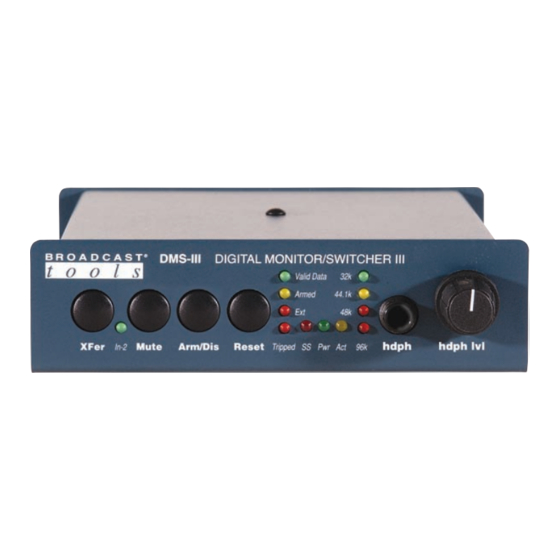
DMS-III
Digital Monitor/Switcher
Firmware Version 1.7 / PCB Ver B
Manual Revised 11/19/2008
Due to the dynamic nature of product design, the information contained in this
document is subject to change without notice. Broadcast Tools, Inc., assumes no
responsibility for errors and/or omissions contained in this document. Revisions
of this information or new editions may be issued to incorporate such changes.
Broadcast Tools® is a registered trademark of Broadcast Tools, Inc.
Copyright, 1989 - 2009 by Broadcast Tools, Inc. All rights reserved.
No part of this document may be reproduced or distributed without permission.
Visit www.broadcasttools.com for important product update information.
Advertisement
Table of Contents

Related Manuals for Broadcast Tools DMS-III


Summary of Contents for Broadcast Tools DMS-III
- Page 1 Manual Revised 11/19/2008 Due to the dynamic nature of product design, the information contained in this document is subject to change without notice. Broadcast Tools, Inc., assumes no responsibility for errors and/or omissions contained in this document. Revisions of this information or new editions may be issued to incorporate such changes.
-
Page 2: Table Of Contents
DMS-III Installation and Operation Manual Table of Contents Section Title Page # Introduction ..........3 Safety Information . -
Page 3: Introduction
If you have any questions regarding your product or you need assistance, please con- read thoroughly before tact your distributor from whom you purchased this equipment. installation and operation. If you would like more information about Broadcast Tools® products, you may reach us at: Broadcast Tools, Inc. 131 State Street Sedro-Woolley, WA 98284 USA Voice: 360 . -
Page 4: Product Description
DMS-III Installation and Operation Manual PRODUCT DESCRIPTION The Broadcast Tools® Digital Monitor & Switcher III is designed to accept and automatically or manually switch two AES signal sources when a digital error and/or analog silence are detected. Features include: Automatic control function that switches to a back up source upon failure of the main source;... -
Page 5: Installation Guidelines
DMS-III Installation and Operation Manual INSTALLATION GUIDELINES Inspection: Please examine your DMS III for any damage that may have been sustained during shipping. If any is noted, please notify the shipper immediately and retain the pack- aging for inspection by the shipper. The package should contain the DMS III, 16 vac@600 ma wall power transformer and this manual. -
Page 6: Remote Control
DMS-III Installation and Operation Manual INSTALLATION GUIDELINES Remote Control Description • Mute This input is used to mute the sonalert alarm. The sonalert may be disabled by removing JP3 on the rear panel. • Reset This input clears all alarms. - Page 7 DMS-III Installation and Operation Manual It is recommended that all cables connected to the DMS III be looped through fer- rite cores to suppress RF. Surge protection with RF filtering such as the Tripp Lite CAUTION! “ISOBAR 4” is also suggested for the power transformer. The purchase of an...
-
Page 8: Programming Guidelines
DMS-III Installation and Operation Manual PROGRAMMING GUIDELINES Switch and jumper Setup: Jp-3 Enables the sonalert (buzzer) Jp-6 Selects either 75, 110-ohm or no termination for input one Jp-7 Selects either 75, 110-ohm or no termination for input two SW2-7, OFF, monitors for both a digital error and/or analog silence alarm. - Page 9 DMS-III Installation and Operation Manual Time Delay Two (2) Second Resolution Table SW1 Switch Position and SW2-6 OFF. Digit Value EXAMPLES: 1 = 2 seconds 1 + 2 = 3 x 2 = 6 seconds 1 + 2 + 4 = 7 x 2 = 14 seconds...
-
Page 10: Restore Delay Timing
DMS-III Installation and Operation Manual Restore timing setup: The DMS III restore time delay is factory configured for 20-second resolution only. Restore delay is set by the first five positions of dipswitch SW2. The default for these switches is OFF. Each switch has a digit value as shown in the table below and refers to the restore time delay in seconds. -
Page 11: Front Panel Led Indicators
DMS-III Installation and Operation Manual Reset switch This switch clears all alarms, sonalert and resets the program switcher. If the alarm still exists, the DMS III will alarm again after the time out delay period. If the DMS III has automatically reset, pressing the reset switch will clear all alarmed indicators and relays. -
Page 12: Specifications
DMS-III Installation and Operation Manual SPECIFICATIONS Inputs: Level - .1Vp-p minimum Two – Switchable, transformer isolated, AES/EBU, 75 or 110-ohm termination. May be disabled for loop-thru installation. Outputs: 1 - Digital – Follows the AES input signal. 1 - Analog Headphone - 32 to 600 ohm. 75 mW peaks. -
Page 13: Warranty
If Broadcast Tools is notified, in writing, of a failure of any item manufactured by Broadcast Tools to conform to the foregoing Limited Warranty within one (1) year following the date of the Buyer’s acquisition of the item, and if the item is returned to Broadcast Tools in accordance with Broadcast Tools’... - Page 14 Restore timing setup: The DMS-III restore time delay is set via SW 2 (OPTIONS), the first FIVE positions of the dipswitch. This provides TWO second resolution when SW2-6 is OFF. The switches are set at the factory for ALL OFF. Each switch has a digit value as shown in the two tables below.
- Page 15 When OFF, the DMS-III switches back to input one from input two when the alarm is cleared or the audio returns. When ON, it allows the DMS-III to stay at input two after the alarm is cleared or the audio returns.
-
Page 16: Application
DMS-III Installation and Operation Manual APPENDIX – APPLICATION APPLICATION...
Need help?
Do you have a question about the DMS-III and is the answer not in the manual?
Questions and answers