Table of Contents
Advertisement
Advertisement
Table of Contents

Related Manuals for MTU 12 V 4000 Lx4


Summary of Contents for MTU 12 V 4000 Lx4
-
Page 1: Operating Instructions
Operating Instructions Gas engine 12 V 4000 Lx4 16 V 4000 Lx4 MS15027/00E... - Page 2 This Publication is protected by copyright and may not be used in any way whether in whole or in part without the prior written permission of MTU Friedrichshafen GmbH. This restriction also applies to copyright, distribution, translation, mi- crofilming and storage or processing on electronic systems including data bases and online services.
-
Page 3: Table Of Contents
Table of Contents 1 Safety 3.8 Engine – Shutdown 3.9 Emergency engine shutdown 1.1 Important provisions for all products 3.10 After stopping the engine – Engine remains 1.2 Personnel and organizational requirements ready for operation 1.3 Safety regulations for startup and operation 3.11 After stopping the engine –... - Page 4 6.9.2 Engine coolant – Change 7 Appendix A 6.9.3 Engine coolant – Draining 7.1 Abbreviations 6.9.4 Engine coolant – Filling 7.2 MTU Onsite Energy contacts / service 6.10 Low-Temperature Circuit partners 6.10.1 Mixture coolant level – Check 6.10.2 Mixture coolant – Change 8 Appendix B 6.10.3 Mixture coolant –...
-
Page 5: Safety
• With fluids and lubricants approved by the manufacturer in accordance with the (→ Fluids and Lubri- cants Specifications of the manufacturer) • With spare parts approved by the manufacturer in accordance with the (→ Spare Parts Catalog/MTU contact/Service partner) •... -
Page 6: Personnel And Organizational Requirements
1.2 Personnel and organizational requirements Organizational measures of the operator This manual must be issued to all personnel involved in operation, maintenance, repair or transporta- tion. Keep this manual handy in the vicinity of the product such that it is accessible to operating, mainte- nance, repair and transport personnel at all times. -
Page 7: Safety Regulations For Startup And Operation
1.3 Safety regulations for startup and operation Safety regulations for startup Install the product correctly and carry out acceptance in accordance the manufacturer's specifications before putting the product into service. Before the product is put into operation for the first time, all official authorizations must be available and commissioning preconditions met. -
Page 8: Safety Regulations For Startup And Operation, Special Instructions For Applications With Gaseous Fuel
1.4 Safety regulations for startup and operation, special instructions for applications with gaseous fuel Gas system Gas supply shut-off: The incomplete machine does not have its own gas supply shutoff device. This must be designed by the plant designer according to site conditions. The connection to the gas supply network is made by the plant designer in accordance with regulations of the DVGW (DVGW490, G490/I). -
Page 9: Safety Regulations For Maintenance And Repair Work
1.5 Safety regulations for maintenance and repair work Safety regulations prior to maintenance and repair work Have maintenance or repair work carried out by qualified and authorized personnel only. Allow the product to cool down to less than 50°C before starting maintenance work (risk of explosion of oil vapors, fluids and lubricants, risk of burning). - Page 10 Ensure particular cleanness during maintenance and repair work on the product. After completion of maintenance and repair work, make sure that no unattached parts are in/on the product (e.g. cloths and cable ties). Safety regulations after completion of maintenance and repair work Before barring, make sure that nobody is standing in the danger zone of the product.
- Page 11 Working on electrical and electronic assemblies Always obtain the permission of the person in charge before commencing maintenance and repair work or switching off any part of the electronic system required to do so. De-energize the appropriate areas prior to working on assemblies. Do not damage cabling during removal work.
-
Page 12: Safety Regulations For Maintenance And Repair Work, Special Instructions For Applications With Gaseous Fuel
1.6 Safety regulations for maintenance and repair work, special instructions for applications with gaseous fuel Safety regulations prior to maintenance and repair work Installation and connection of the gas supply must only be carried out by a specialized company with staff that has been trained and authorized for this task. -
Page 13: Fire Prevention And Environmental Protection, Fluids And Lubricants, Auxiliary Materials
The latest version can be found on the website on the "Technical Info" or "Spare Parts and Service" tabs at http://www.mtu-online.com. Consumable fluids and materials may also be hazardous or toxic. When using fluids, lubricants, consum- ables and other chemical substances, follow the safety regulations that apply to the product. -
Page 14: Compressed Air
Lead • Adopt suitable measures to avoid the formation of lead dust. • Switch on extraction system. • When working with lead or pastes that contain lead, avoid direct contact with the skin. Do not inhale lead vapors. • Wash hands after contact with lead or lead-containing substances. Compressed air Observe special safety precautions when working with compressed air: •... -
Page 15: Fire Prevention And Environmental Protection, Fluids And Lubricants, Auxiliary Materials, Special Instructions For Applications With Gaseous Fuel
1.8 Fire prevention and environmental protection, fluids and lubricants, auxiliary materials, special instructions for applications with gaseous fuel Natural gas Observe the safety data sheet. Caution: Highly flammable gas, forms an explosive mixture with air/oxygen. Caution: Weak narcotic gas, risk of suffocation at very high concentration. All gas-carrying lines must be checked for leaks prior to commissioning and at regular intervals during operation. -
Page 16: Standards For Safety Notices In The Text
1.9 Standards for safety notices in the text DANGER In the event of immediate danger. Consequences: Death, serious or permanent injury! • Remedial action. WARNING In the event of a situation involving potential danger. Consequences: Death, serious or permanent injury! •... -
Page 17: Transport
Only set down engine on a firm, level surface. Make sure that the consistency and load-bearing capacity of the ground or support surface is adequate. Never set an engine down on the oil pan unless expressively authorized to do so by MTU on a case-to- case basis. -
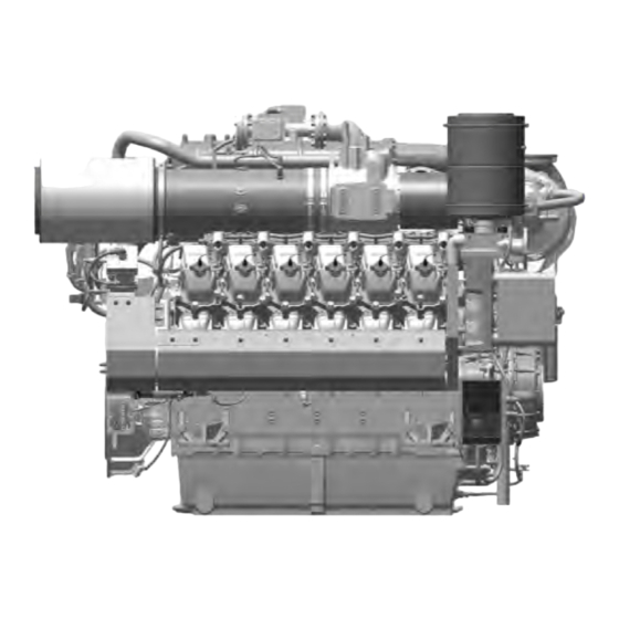
Page 18: Product Summary
2 Product Summary 2.1 Engine overview 1 Engine governor/engine 5 Engine lifting equipment 9 Engine mounting bracket, monitoring 6 Capacitor ignition system driving end 2 Throttle 7 Engine mounting bracket - 10 Flywheel 3 Mixture cooler free end 11 Air filter/air inlet 4 Exhaust turbocharger 8 Oil pan KS Driving end... - Page 19 1 Crankcase breather, oil 6 Spark plug 11 Oil level switch separator 7 Cylinder head cover 12 Connection: engine cool- 2 Exhaust outlet 8 Cylinder head ant inlet 3 Gas control valve 9 Oil filter 13 Engine oil heat exchanger 4 Gas inlet connection 10 Engine oil sampling con- 14 Connection: engine cool-...
-
Page 20: Engine Side And Cylinder Designations
2.2 Engine side and cylinder designations Engine sides are always designated as viewed from the driving end (KS) (4). For designation of the cylinders (to DIN ISO 1204) the letter "A" (1) is used to refer to the cylinders on the left-hand side of the engine and the letter "B"... -
Page 21: Main Engine Dimensions
2.3 Main engine dimensions Main engine dimensions Length 12V (A) approx. 2868 mm Length 16V (A) approx. 3372 mm Width 12V (B) approx. 1742 mm Width 16V (B) approx. 1789 mm Height 12V (C) approx. 2146 mm Height 16V (C) approx. -
Page 22: Ignition Order
2.4 Ignition order Ignition order 12 V A1-B2-A5-B4-A3-B1-A6-B5-A2-B3-A4-B6 16 V A1-A7-B4-B6-A4-B8-A2-A8-B3-B5-A3-A5-B2-A6-B1-B7 22 | Product Summary | MS15027/00E 2013-10... -
Page 23: Technical Data
2.5 Technical Data 2.5.1 12 V 4000 L64, 16 V 4000 L64 engine data, fuel optimized ("TA-Luft") Explanation: DL Ref. value: Continuous power BL Ref. value: Fuel stop power A Design value G Guaranteed value r Guideline value L Limit value, up to which the engine can be operated, without change (e.g. of power settings). N Not yet defined value - Not applicable X Applicable... - Page 24 Number of cylinders Gas type: natural gas Methane number, min. Table 6: General conditions (for maximum power) Consumption Number of cylinders Lube oil consumption after 1000 h run time g/kWh Table 7: Consumption Model-related data (basic design) Number of cylinders Operating method: Four-stroke cycle, Otto engine, single-acting Combustion method: Mixture charging, spark ignition Number of cylinders...
- Page 25 Number of cylinders Thermostat: Starts to open °C Thermostat: Opening stops (thermostat fully open and bypass °C closed Table 9: Coolant system (HT circuit) Coolant system (LT circuit) Number of cylinders Coolant temperature before mixture cooler (at engine connection: °C inlet from cooling equipment (w/o antifreeze) Coolant antifreeze content, max.
-
Page 26: Exhaust Emissions
Number of cylinders Minimum idling speed 1500 1500 Limit speed for overspeed alarm/emergency shutdown 1900 1900 Table 13: General operating data Starter (electric) Number of cylinders Starter, rated power (standard design) 2 x 9 Rated starter voltage (standard design) Starter, current consumption, max. (standard design) 2500 2 x 2500 Starting-attempt duration, max. -
Page 27: 4000 L64, 16V 4000 L64 Engine Data, Emissions-Optimized (1/2 "Ta-Luft")
2.5.2 12V 4000 L64, 16V 4000 L64 engine data, emissions-optimized (1/2 "TA-Luft") Explanation: DL Ref. value: Continuous power BL Ref. value: Fuel stop power A Design value G Guaranteed value r Guideline value L Limit value, up to which the engine can be operated, without change (e.g. of power settings). N Not yet defined value - Not applicable X Applicable... - Page 28 Consumption Number of cylinders Lube oil consumption after 1000 h run time g/kWh Table 22: Consumption Model-related data (basic design) Number of cylinders Operating method: Four-stroke cycle, Otto engine, single-acting Combustion method: Mixture charging, spark ignition Number of cylinders Cylinder arrangement: V-angle Degrees (°) Bore...
- Page 29 Coolant system (LT circuit) Number of cylinders Coolant temperature before mixture cooler (at engine connection: °C inlet from cooling equipment (w/o antifreeze) Coolant antifreeze content, max. Coolant pump: Volumetric flow m³/h Pressure in cooling system, max. Pressure loss over mixture cooler (at nominal flow rate 8.56) 0.31 Table 25: Coolant system (LT circuit) Lube oil system...
- Page 30 Number of cylinders Starter, current consumption, max. (standard design) 2500 2 x 2500 Starting-attempt duration, max. Number of teeth on starter ring gear Table 29: Starter (electric) Oil and coolant capacity Number of cylinders Engine coolant capacity, engine side (without cooling equipment) Liters Mixture coolant, engine side (without cooling system) Liters...
-
Page 31: Monitoring, Control And Regulation Equipment
2.6 Monitoring, Control and Regulation Equipment 2.6.1 Gas engine phase 4 system – Overview Overview 1 Unit system 5 Engine Monitoring Unit 9 Knock module 2 Engine system 6 Humidity sensor 10 Ignition 3 System 7 Throttles 11 Compressor bypass 4 Engine governor 8 Gas control unit 12 NOx sensor (optional) - Page 32 Anti-knock control AKR • Controls monitored cylinders re. knock characteristics. If knocking is detected, the ignition timing is retarded on the cylinder in question. If this does not result in an improvement, the power is reduced. Gas control valve TecJet52 / TecJet85 •...
-
Page 33: Purpose Of The Units
2.6.2 Purpose of the units ECU 9 engine governor Central control and monitoring unit for the engine • Communication with other devices and higher-level systems via CAN bus • Control of throttles (mixture and gas) • Registration and analysis of engine operating states •... - Page 34 Engine Monitoring Unit EMU 8 EMU = Engine Monitoring Unit Monitoring unit for the engine • Acquisition and processing of cylinder exhaust temperatures Self-monitoring 34 | Product Summary | MS15027/00E 2013-10...
-
Page 35: Operation
3 Operation 3.1 Runtimes at partial load Gas engines were designed and optimized for continuous operation at 100% load. The following restrictions apply to ensure maximum operational availability of the engine plant and to reduce maintenance to a minimum: Power, referenced to nominal Recommended maximum run- Recommended minimum run- load... -
Page 36: Putting The Engine Into Operation After Extended Out-Of-Service Periods (>3 Months)
3.2 Putting the engine into operation after extended out-of-service periods (>3 months) Preconditions ☑Engine is stopped and starting disabled. ☑MTU Fluids and Lubricants Specifications (A001061/..) are available. Putting the engine into operation after extended out-of-service-periods (>3 months) Item Measure Engine Depreserve (→... -
Page 37: Putting The Engine Into Operation After Scheduled Out-Of-Service-Period
3.3 Putting the engine into operation after scheduled out-of- service-period Preconditions ☑Engine shut down and starting disabled. Putting into operation Item Measure Lube oil system Check oil level in oil storage tank (→ Page 173). Coolant circuit Check engine coolant level (→ Page 177); Check mixture coolant level (→... -
Page 38: Control, Starting And Stopping Sequences
3.4 Control, starting and stopping sequences NOTICE Risk of engine damage due to incorrect action. Risk of severe damage to property! • Ensure engine is ready for operation before starting. See engine documentation. Starting and stopping sequences The starting sequence is software-controlled and depends on the place of start command input. To ensure that no mixture is in the engine when ignition is switched on or off, which is a specific re- quirement for gas engines, special procedures for engine start / stop are specified. - Page 39 Emergency stop sequence If an emergency stop command is activated, the following steps are carried out automatically: 1. Closing gas supply solenoid valves 2. Closing mixture throttles 3. Engine running down to standstill 4. Deactivating ignition 5. Requesting external ventilation by contact Restarting after emergency stop A scavenging phase and a request for external ventilation by contact ensue following a start request after emergency shutdown.
-
Page 40: Engine - Start
3.5 Engine – Start Preconditions ☑Generator not connected to network. ☑Start interlock not active. DANGER Rotating and moving engine parts. Risk of crushing, danger of parts of the body being caught or pulled in! • Before cranking the engine with starter system, make sure that there are no persons in the en- gine's danger zone. -
Page 41: Operational Checks
3.6 Operational checks DANGER Rotating and moving engine parts. Risk of crushing, danger of parts of the body being caught or pulled in! • Only run the engine at low power. Keep away from the engine's danger zone. WARNING High level of engine noise when the engine is running. Risk of damage to hearing! •... -
Page 42: Emission Values - Check
Special tools, Material, Spare parts Designation / Use Part No. Qty. Gas measuring and warning device (not stocked by MTU) DANGER Rotating and moving engine parts. Risk of crushing, danger of parts of the body being caught or pulled in! •... -
Page 43: Engine - Shutdown
3.8 Engine – Shutdown Preconditions ☑Generator is not connected to network. NOTICE Stopping the engine when it is running at full load subjects it to extreme thermal and mechanical stresses. Overheating of and, therefore, damage to components is possible! • Before shutting down the engine, allow it to idle until the engine temperatures decrease and constant levels are indicated. -
Page 44: Emergency Engine Shutdown
3.9 Emergency engine shutdown WARNING Escaping residual gas may create an explosive atmosphere in case of emergency stop. Explosion hazard! • Ensure that any escaping residual gas is routed out by means of appropriate facility ventilation and use of an SBV (safety blow-off valve) to prevent any risk of explosive atmosphere. •... - Page 45 Item Action • A contact is provided to request the ventilation system in the scaveng- ing phase. • The gas control system must be equipped with an SAV (safety shut-off Note: Gas train valve) when using gas control systems with inlet pressures in excess of 0.1 bar.
-
Page 46: After Stopping The Engine - Engine Remains Ready For Operation
3.10 After stopping the engine – Engine remains ready for operation After stopping the engine Item Action Engine/generator control Select operating mode, e.g. HAND, MANUAL, AUTO, AUTOMATIC. (manufacturer-specific) 46 | Operation | MS15027/00E 2013-10... -
Page 47: After Stopping The Engine - Putting The Engine Out Of Operation
If the engine is to remain out of service for more than 1 month, carry out preservation (→ MTU Preservation and Represerva- tion Specifications A001070/..). The corrosion-inhibiting effect of the engine coolant may be used as an alter- native in case of out-of-service periods lasting for more than 1 month, by run- ning the engine for at least 2 hours at rated power once a month. -
Page 48: Maintenance
4 Maintenance 4.1 50-hours check 50-hours check One-time operations to be carried out after the first 50 operating hours of the cylinder head (with a new engine, after installation of new cylinder heads, after component maintenance or extended component maintenance). When installing a cylinder head with run-in mating faces (e.g. -
Page 49: Maintenance Schedule Reference Table [Ql1]
4.2 Maintenance schedule reference table [QL1] The maintenance tasks and intervals for this product are defined in the Maintenance Schedule. The Maintenance Schedule is a stand-alone publication. The task numbers in this table provide reference to the maintenance tasks specified in the Maintenance Schedule. -
Page 50: Troubleshooting
OEM (see documentation of the genset man- ufacturer). A prerequisite for performing the measures to rectify faults is corresponding qualification/training at MTU. Contact Service should troubleshooting as prescribed in the fault code list prove unsuccessful. Recommended action in case of alarm... - Page 51 Red alarm: Caution, the engine is running at its limits. Shut down manually without further delay if the engine does not shut itself down immediately after a red alarm is signaled. MS15027/00E 2013-10 | Troubleshooting | 51...
-
Page 52: Fault Messages On Log For Genset Control
5.2 Fault messages on log for genset control 112222 – HI T-Exhaust Mean Yellow alarm. Initiated by EMU. Cause Corrective action Weighted average of all 1. Check emission values. individual exhaust gas 2. Check ignition timing (→ Page 160). temperatures is too high. 3. - Page 53 112304 – HI T-Exhaust A4 Yellow alarm. Initiated by EMU. Cause Corrective action Individual exhaust gas 1. Check emission values. temperature of this cylinder is 2. Check ignition timing (→ Page 160). too high in comparison with 3. Check valve drive (exhaust valves do not close). weighted average.
- Page 54 112309 – HI T-Exhaust A9 Yellow alarm. Initiated by EMU. Cause Corrective action Individual exhaust gas 1. Check emission values. temperature of this cylinder is 2. Check ignition timing (→ Page 160). too high in comparison with 3. Check valve drive (exhaust valves do not close). weighted average.
- Page 55 112314 – HI T-Exhaust B4 Yellow alarm. Initiated by EMU. Cause Corrective action Individual exhaust gas 1. Check emission values. temperature of this cylinder is 2. Check ignition timing (→ Page 160). too high in comparison with 3. Check valve drive (exhaust valves do not close). weighted average.
- Page 56 112319 – HI T-Exhaust B9 Yellow alarm. Initiated by EMU. Cause Corrective action Individual exhaust gas 1. Check emission values. temperature of this cylinder is 2. Check ignition timing (→ Page 160). too high in comparison with 3. Check valve drive (exhaust valves do not close). weighted average.
- Page 57 112404 – LO T-Exhaust A4 Yellow alarm. Initiated by EMU. Cause Corrective action Individual exhaust gas 1. Check spark plug. temperature of this cylinder is 2. Check emission values. too high in comparison with 3. Check ignition timing (→ Page 160). weighted average.
- Page 58 112409 – LO T-Exhaust A9 Yellow alarm. Initiated by EMU. Cause Corrective action Individual exhaust gas 1. Check spark plug. temperature of this cylinder is 2. Check emission values. too high in comparison with 3. Check ignition timing (→ Page 160). weighted average.
- Page 59 112414 – LO T-Exhaust B4 Yellow alarm. Initiated by EMU. Cause Corrective action Individual exhaust gas 1. Check spark plug. temperature of this cylinder is 2. Check emission values. too high in comparison with 3. Check ignition timing (→ Page 160). weighted average.
- Page 60 112419 – LO T-Exhaust B9 Yellow alarm. Initiated by EMU. Cause Corrective action Individual exhaust gas 1. Check spark plug. temperature of this cylinder is 2. Check emission values. too high in comparison with 3. Check ignition timing (→ Page 160). weighted average.
- Page 61 112504 – HIHI T-Exhaust A4 Red alarm. Initiated by EMU. Cause Corrective action Individual exhaust gas 1. Check emission values. temperature of this cylinder is 2. Check ignition timing (→ Page 160). too high in comparison with 3. Check valve drive (exhaust valves do not close). weighted average.
- Page 62 112509 – HIHI T-Exhaust A9 Red alarm. Initiated by EMU. Cause Corrective action Individual exhaust gas 1. Check emission values. temperature of this cylinder is 2. Check ignition timing (→ Page 160). too high in comparison with 3. Check valve drive (exhaust valves do not close). weighted average.
- Page 63 112514 – HIHI T-Exhaust B4 Red alarm. Initiated by EMU. Cause Corrective action Individual exhaust gas 1. Check emission values. temperature of this cylinder is 2. Check ignition timing (→ Page 160). too high in comparison with 3. Check valve drive (exhaust valves do not close). weighted average.
- Page 64 112519 – HIHI T-Exhaust B9 Red alarm. Initiated by EMU. Cause Corrective action Individual exhaust gas 1. Check emission values. temperature of this cylinder is 2. Check ignition timing (→ Page 160). too high in comparison with 3. Check valve drive (exhaust valves do not close). weighted average.
- Page 65 112604 – LOLO T-Exhaust A4 Red alarm. Initiated by EMU. Cause Corrective action Individual exhaust gas 1. Check spark plug. temperature of this cylinder is 2. Check emission values. too low in comparison with 3. Check ignition timing (→ Page 160). weighted average.
- Page 66 112609 – LOLO T-Exhaust A9 Red alarm. Initiated by EMU. Cause Corrective action Individual exhaust gas 1. Check spark plug. temperature of this cylinder is 2. Check emission values. too low in comparison with 3. Check ignition timing (→ Page 160). weighted average.
- Page 67 112614 – LOLO T-Exhaust B4 Red alarm. Initiated by EMU. Cause Corrective action Individual exhaust gas 1. Check spark plug. temperature of this cylinder is 2. Check emission values. too low in comparison with 3. Check ignition timing (→ Page 160). weighted average.
- Page 68 112619 – LOLO T-Exhaust B9 Red alarm. Initiated by EMU. Cause Corrective action Individual exhaust gas 1. Check spark plug. temperature of this cylinder is 2. Check emission values. too low in comparison with 3. Check ignition timing (→ Page 160). weighted average.
- Page 69 112705 – HIHI T-Exhaust A5 (abs) Red alarm. Initiated by EMU. Cause Corrective action Individual exhaust gas 1. Check emission values. temperature of this cylinder is 2. Check ignition timing (→ Page 160). too high. 3. Check valve drive (exhaust valves do not close). 112706 –...
- Page 70 112711 – HIHI T-Exhaust B1 (abs) Red alarm. Initiated by EMU. Cause Corrective action Individual exhaust gas 1. Check emission values. temperature of this cylinder is 2. Check ignition timing (→ Page 160). too high. 3. Check valve drive (exhaust valves do not close). 112712 –...
- Page 71 112717 – HIHI T-Exhaust B7 (abs) Red alarm. Initiated by EMU. Cause Corrective action Individual exhaust gas 1. Check emission values. temperature of this cylinder is 2. Check ignition timing (→ Page 160). too high. 3. Check valve drive (exhaust valves do not close). 112718 –...
- Page 72 113601 – AL Gas Valve 1 feedback Red alarm. Initiated by SAM. Cause Corrective action u Check valve 1 and cabling. Feedback signal from valve 1 does not correspond with setpoint signal. 113902 – SS Local Initiated Emerg. Stop Red alarm. Initiated by SAM. Cause Corrective action Emergency stop detected.
- Page 73 1.4510.192 – Knock Sensor Error A1 Red alarm. Initiated by antiknock control. Cause Corrective action No signal from this knock 1. Check cabling. sensor. 2. Check sensor (tightening torque, damage), replace as necessary. 1.4510.193 – Knock Sensor Error A2 Red alarm. Initiated by antiknock control. Cause Corrective action No signal from this knock...
- Page 74 1.4510.198 – Knock Sensor Error A7 Red alarm. Initiated by antiknock control. Cause Corrective action No signal from this knock 1. Check cabling. sensor. 2. Check sensor (tightening torque, damage), replace as necessary. 1.4510.199 – Knock Sensor Error A8 Red alarm. Initiated by antiknock control. Cause Corrective action No signal from this knock...
- Page 75 1.4510.204 – Knock Sensor Error B3 Red alarm. Initiated by antiknock control. Cause Corrective action No signal from this knock 1. Check cabling. sensor. 2. Check sensor (tightening torque, damage), replace as necessary. 1.4510.205 – Knock Sensor Error B4 Red alarm. Initiated by antiknock control. Cause Corrective action No signal from this knock...
- Page 76 1.4510.210 – Knock Sensor Error B9 Red alarm. Initiated by antiknock control. Cause Corrective action No signal from this knock 1. Check cabling. sensor. 2. Check sensor (tightening torque, damage), replace as necessary. 1.4510.211 – Knock Sensor Error B10 Red alarm. Initiated by antiknock control. Cause Corrective action No signal from this knock...
- Page 77 1.4520.523 – MIC5 Stat W: invalid configuration Yellow alarm. Initiated by MIC5. Cause Corrective action u Check settings. Restart ignition control unit. The ignition system settings are invalid. 1.4520.524 – MIC5 Stat W: invalid trigger config Yellow alarm. Initiated by MIC5. Cause Corrective action The ignition system settings are...
- Page 78 1.4520.530 – MIC5 Stat Global timing limited Yellow alarm. Initiated by MIC5. Cause Corrective action u Check settings. The global timing is outside of the valid range. 1.4520.540 – MIC5 E1 General fault Red alarm. Initiated by MIC5. Cause Corrective action A general fault occurred.
- Page 79 1.4520.546 – MIC5 E1 Failure temperature sensor Red alarm. Initiated by MIC5. Cause Corrective action u Restart ignition control unit. The temperature sensor is defective. 1.4520.547 – MIC5 E1 Failure current sensor Red alarm. Initiated by MIC5. Cause Corrective action The current sensor is defective.
- Page 80 1.4520.553 – MIC5 E1 Tr1 polarity detection fail Yellow alarm. Initiated by MIC5. Cause Corrective action u Check sensor, sensor spacing, cabling, settings in data record Polarity of trigger 1 (B1.2) could not be detected. and timing wheel. Replace sensor if required. 1.4520.554 –...
- Page 81 1.4520.560 – MIC5 E1 Tr1 index too early / faulty Yellow alarm. Initiated by MIC5. Cause Corrective action u Check sensor, sensor spacing, cabling, settings in data record The index mark of trigger 1 (B1.2) was detected too early or and timing wheel.
- Page 82 1.4520.575 – MIC5 IPE Primary Open Cylinder 6 Yellow alarm. Initiated by MIC5. Cause Corrective action Disruption in primary circuit of 1. Check cabling to ignition coil. cylinder 6 in firing order. 2. Check ignition coil. 1.4520.576 – MIC5 IPE Primary Open Cylinder 7 Yellow alarm.
- Page 83 1.4520.582 – MIC5 IPE Primary Open Cylinder 13 Yellow alarm. Initiated by MIC5. Cause Corrective action Disruption in primary circuit of 1. Check cabling to ignition coil. cylinder 13 in firing order. 2. Check ignition coil. 1.4520.583 – MIC5 IPE Primary Open Cylinder 14 Yellow alarm.
- Page 84 1.4520.589 – MIC5 IPE Primary Open Cylinder 20 Yellow alarm. Initiated by MIC5. Cause Corrective action Disruption in primary circuit of 1. Check cabling to ignition coil. cylinder 20 in firing order. 2. Check ignition coil. 1.4520.590 – MIC5 IPE Prim Short Circuit Cyl 1 Yellow alarm.
- Page 85 1.4520.596 – MIC5 IPE Prim Short Circuit Cyl 7 Yellow alarm. Initiated by MIC5. Cause Corrective action Short circuit in primary circuit of 1. Check cabling to ignition coil. cylinder 7 in firing order. 2. Check ignition coil. 1.4520.597 – MIC5 IPE Prim Short Circuit Cyl 8 Yellow alarm.
- Page 86 1.4520.603 – MIC5 IPE Prim Short Circuit Cyl 14 Yellow alarm. Initiated by MIC5. Cause Corrective action Short circuit in primary circuit of 1. Check cabling to ignition coil. cylinder 14 in firing order. 2. Check ignition coil. 1.4520.604 – MIC5 IPE Prim Short Circuit Cyl 15 Yellow alarm.
- Page 87 1.4520.610 – MIC5 ISE Secondary Open Cylinder 1 Yellow alarm. Initiated by MIC5. Cause Corrective action Disruption in secondary circuit 1. Check ignition line, spark plug connector and spark plug. of cylinder 1 in firing order. 2. Check ignition coil. 1.4520.611 –...
- Page 88 1.4520.617 – MIC5 ISE Secondary Open Cylinder 8 Yellow alarm. Initiated by MIC5. Cause Corrective action Disruption in secondary circuit 1. Check ignition line, spark plug connector and spark plug. of cylinder 8 in firing order. 2. Check ignition coil. 1.4520.618 –...
- Page 89 1.4520.624 – MIC5 ISE Secondary Open Cylinder 15 Yellow alarm. Initiated by MIC5. Cause Corrective action Disruption in secondary circuit 1. Check ignition line, spark plug connector and spark plug. of cylinder 15 in firing order. 2. Check ignition coil. 1.4520.625 –...
- Page 90 1.4520.631 – MIC5 ISE Secon Short Circuit Cyl 2 Yellow alarm. Initiated by MIC5. Cause Corrective action Short circuit in secondary circuit 1. Check ignition line, spark plug connector and spark plug. of cylinder 2 in firing order. 2. Check ignition coil. 1.4520.632 –...
- Page 91 1.4520.638 – MIC5 ISE Secon Short Circuit Cyl 9 Yellow alarm. Initiated by MIC5. Cause Corrective action Short circuit in secondary circuit 1. Check ignition line, spark plug connector and spark plug. of cylinder 9 in firing order. 2. Check ignition coil. 1.4520.639 –...
- Page 92 1.4520.645 – MIC5 ISE Secon Short Circuit Cyl 16 Yellow alarm. Initiated by MIC5. Cause Corrective action Short circuit in secondary circuit 1. Check ignition line, spark plug connector and spark plug. of cylinder 16 in firing order. 2. Check ignition coil. 1.4520.646 –...
- Page 93 1.4520.660 – MIC5 E2 Tr2 no signal detected Yellow alarm. Initiated by MIC5. Cause Corrective action u Check sensor, sensor spacing, cabling, settings in data record No signal from trigger 2 (B75). and timing wheel. Replace sensor if required. 1.4520.661 – MIC5 E2 Tr2 polarity detection fail Yellow alarm.
- Page 94 1.4520.667 – MIC5 E2 Tr2 index mark not detected Yellow alarm. Initiated by MIC5. Cause Corrective action u Check sensor, sensor spacing, cabling, settings in data record The index mark of trigger 2 (B75) was not detected during and timing wheel. Replace sensor if required. operation.
- Page 95 1.4520.673 – MIC5 E2 Tr3 polarity detection fail Yellow alarm. Initiated by MIC5. Cause Corrective action u Check sensor, sensor spacing, cabling, settings in data record Polarity of trigger 3 (B13.2) could not be detected. and timing wheel. Replace sensor if required. 1.4520.674 –...
- Page 96 1.4520.680 – MIC5 E2 Tr3 index too early / faulty Yellow alarm. Initiated by MIC5. Cause Corrective action u Check sensor, sensor spacing, cabling, settings in data record The index mark of trigger 3 (B13.2) was detected too early and timing wheel. Replace sensor if required. or was faulty.
- Page 97 1.4530.012 – Analog Input High Error Yellow alarm. Initiated by F-Series. Cause Corrective action u Check setting. F-Series setting is not correct. 1.4530.013 – Analog Input Low Error Yellow alarm. Initiated by F-Series. Cause Corrective action F-Series setting is not correct. u Check setting.
- Page 98 1.4530.019 – Run Enable not active Yellow alarm. Initiated by F-Series. Cause Corrective action u Check setting. F-Series setting is not correct. 1.4530.020 – Spring Check Failed Yellow alarm. Initiated by F-Series. Cause Corrective action F-Series setting is not correct. u Check setting.
- Page 99 1.4540.012 – Valve Position Error Red alarm. Initiated by TecJet. Cause Corrective action u Restart TecJet. Hardware not ready for operation. 1.4540.013 – High Elec Temp Red alarm. Initiated by TecJet. Cause Corrective action Hardware not ready for u Restart TecJet. operation.
- Page 100 1.4540.019 – Position Fail High Red alarm. Initiated by TecJet. Cause Corrective action u Restart TecJet. Hardware not ready for operation. 1.4540.020 – Elec Temp Fail Low Red alarm. Initiated by TecJet. Cause Corrective action Hardware not ready for u Restart TecJet. operation.
- Page 101 1.4540.026 – Analog Input Low Error Red alarm. Initiated by TecJet. Cause Corrective action u Check setting. TecJet setting is not correct. 1.4540.027 – Analog Input High Error Red alarm. Initiated by TecJet. Cause Corrective action TecJet setting is not correct. u Check setting.
- Page 102 1.4540.033 – Battery Volt High Error Red alarm. Initiated by TecJet. Cause Corrective action Supply voltage has reached 1. Check supply voltage. maximum limit value. 2. Check cabling. 1.4540.034 – FGT High Limit Error Red alarm. Initiated by TecJet. Cause Corrective action Hardware not ready for u Restart TecJet.
- Page 103 1.4540.041 – TecJet Internal Fault Red alarm. Initiated by TecJet. Cause Corrective action u Restart TecJet. Hardware not ready for operation. 1.4540.042 – Keyswitch State Red alarm. Initiated by TecJet. Cause Corrective action Keyswitch cabling missing. u Check cabling. 1.4540.043 – Parameter Error Red alarm.
- Page 104 1.4540.048 – SPI ADC Error Red alarm. Initiated by TecJet. Cause Corrective action u Restart TecJet. Hardware not ready for operation. 1.4540.049 – Sense 5V Error Red alarm. Initiated by TecJet. Cause Corrective action Hardware not ready for u Restart TecJet. operation.
- Page 105 1.4540.055 – Factory CAL Error Red alarm. Initiated by TecJet. Cause Corrective action u Restart TecJet. Hardware not ready for operation. 1.4540.056 – PWM Duty Cycle High Error Red alarm. Initiated by TecJet. Cause Corrective action TecJet setting is not correct. u Check setting.
- Page 106 1.4550.036 – A - Temperature derating active Yellow alarm. Initiated by ProAct A-Bank. Cause Corrective action The internal temperature is 1. Check room temperature. Restart ProAct. higher than the limit. 2. Restart ProAct. 1.4550.037 – A - Temperature above 120 °C Red alarm.
- Page 107 1.4550.043 – A - CAN Fault (CAN Bus Off, CAN Ad) Red alarm. Initiated by ProAct A-Bank. Cause Corrective action u Check cabling and setting. CAN bus connection faulty. 1.4550.044 – A - CAN Stop Command Yellow alarm. Initiated by ProAct A-Bank. Cause Corrective action "Stop"...
- Page 108 1.4550.136 – B - Temperature derating active Yellow alarm. Initiated by ProAct B-Bank. Cause Corrective action The internal temperature is 1. Check room temperature. Restart ProAct. higher than the limit. 2. Restart ProAct. 1.4550.137 – B - Temperature above 120 °C Red alarm.
- Page 109 1.4550.143 – B - CAN Fault (CAN Bus Off, CAN Ad) Red alarm. Initiated by ProAct B-Bank. Cause Corrective action u Check cabling and setting. CAN bus connection faulty. 1.4550.144 – B - CAN Stop Command Yellow alarm. Initiated by ProAct B-Bank. Cause Corrective action "Stop"...
-
Page 110: Engine Governor - Fault Messages
5.3 Engine governor – Fault messages 015 – LO P-Lube Oil Yellow alarm. Associated parameter 2.0100.921 Cause Corrective action Engine oil pressure too low (limit 1. Check oil system, oil heat exchanger. value 1). No oil in engine, engine 2. Replace oil filter (→ Page 176). speed too low, oil lines, oil heat 3. - Page 111 021 – HI T-Exhaust B Yellow alarm. Associated parameter 2.0127.931 Cause Corrective action Exhaust gas temperature (B 1. Check exhaust turbocharger. side) after turbine too high (limit 2. Check ignition timing (→ Page 160). value 1). Incorrect ignition 3. Check mixture setting. timing, mixture too lean or too 4.
- Page 112 031 – HI ETC1 Overspeed Yellow alarm. Associated parameter 2.3011.931 Cause Corrective action u Turbocharger speed sensor is not fitted at present. Check ECU Speed of primary turbocharger too high (limit value 1). setting for this input. 032 – SS ETC1 Overspeed Red alarm.
- Page 113 052 – SS T-Lube Oil Red alarm. Engine stop. Associated parameter 2.0125.932 Cause Corrective action Engine oil temperature after oil 1. Check engine coolant circuit. heat exchanger too high (limit 2. Check oil heat exchanger. value 2). Oil heat exchanger 3.
- Page 114 063 – HI P-Crankcase Yellow alarm. Associated parameter 2.0106.931 Cause Corrective action Crankcase pressure too high 1. Check crank drive: (limit value 1). Restrictor valve in • Crank engine (→ Page 147). crankcase breather is closed too • Endoscope combustion chambers from bottom dead center much, air filter is defective, oil to top dead center.
- Page 115 089 – SS Engine Speed too Low Red alarm. Engine stop. Associated parameter 2.2500.030 Cause Corrective action Engine stalls. In normal 1. In parallel operation connected to mains: operation the engine speed is • Check mains for frequency drop. below the limit set in parameter •...
- Page 116 093 – SS T-Preheat Red alarm. Engine stop. Associated parameter 2.1090.922 Cause Corrective action Preheating temperature too low 1. Check preheating. (limit value 2). coolant 2. Check differential coolant pressure. temperature too low for engine 3. Check heating elements. start. 4.
- Page 117 119 – LOLO ECU Power Supply Voltage Red alarm. Associated parameter 2.0140.922 Cause Corrective action Supply voltage too low (limit 1. Check supply voltage. value 2). 2. Check cabling. 120 – HI ECU Power Supply Voltage Yellow alarm. Associated parameter 2.0140.931 Cause Corrective action Supply voltage too high (limit...
- Page 118 182 – AL CAN Wrong Parameters Red alarm. Associated parameter 2.0500.682 Cause Corrective action u Contact Service (configuration fault). Wrong parameter value entered in data record. 183 – AL CAN No PU-Data Red alarm. Associated parameter 2.0500.683 Cause Corrective action The selected CAN mode u Contact Service (configuration fault).
- Page 119 188 – AL CAN2 Bus Off Yellow alarm. Associated parameter 2.0500.688 Cause Corrective action u Check operation of nodes and cabling. CAN controller 2 is in "Bus-Off" status. Automatic switching to CAN bus 1. Bus nodes (ECU, SAM or EMU) faulty. 189 –...
- Page 120 206 – SD T-Exhaust A Yellow alarm. Associated parameter 1.8004.576 Cause Corrective action u Check sensor and cabling (B4.21), replace if necessary. Fault is Exhaust temperature sensor on A side defective, short circuit or rectified following engine restart. wire break. 207 –...
- Page 121 216 – SD T-Lube Oil Red alarm. Engine stop. Associated parameter 1.8004.575 Cause Corrective action u Check sensor and cabling (B7), replace as necessary. Fault is Engine oil temperature sensor after oil heat exchanger rectified following engine restart. defective, short circuit or wire break.
- Page 122 231 – SD Camshaft Speed Red alarm. Engine stop. Associated parameter 1.8004.499 Cause Corrective action u Check sensor and cabling (B1.1), replace if necessary. Fault is Camshaft sensor defective, short circuit or wire break. rectified following engine restart. 232 – SD Charger 1 Speed Yellow alarm.
- Page 123 381 – AL Wiring TOP 1 Yellow alarm. Associated parameter 2.8006.638 Cause Corrective action u Check cabling. Short circuit or wire break on transistor output, plant-side 1 (TOP 1). Activation of yellow combined alarm faulty. 382 – AL Wiring TOP 2 Red alarm.
- Page 124 419 – SD T-Coolant b.Engine Red alarm. Associated parameter 1.8004.604 Cause Corrective action u Check sensor and cabling (B6.3), replace if necessary. Coolant temperature sensor at engine inlet defective, short circuit or wire break. 423 – LO P-Coolant Diff. Red alarm. Engine stop. Associated parameter 2.0180.921 Cause Corrective action...
- Page 125 434 – HI T-Coolant Before Engine Yellow alarm. Associated parameter 2.0173.931 Cause Corrective action u Check engine coolant circuit (pressure and flow). Coolant temperature before engine too high (limit value 1). Engine coolant pump failure, flow too low, air in engine cooling system.
- Page 126 451 – HI T-Charge Mix Yellow alarm. Associated parameter 2.0169.931 Cause Corrective action Mixture temperature is too high 1. Check mixture cooling circuit. (limit value 1). Mixture coolant 2. Check mixture cooler for dirt. pump failure, volumetric flow too low, cooling system inlet temperature too high, mixture cooler clogged.
- Page 127 458 – LOLO T-Intake Air Red alarm. Engine stop. Associated parameter 2.0123.922 Cause Corrective action u Check ventilation system. Intake air temperature is too low (limit value 4). 459 – SD P-Coolant b. Engine Red alarm. Associated parameter 1.8004.627 Cause Corrective action Coolant pressure sensor before u Check sensor and cabling (B16.3), replace if necessary.
- Page 128 479 – AL Comb. Alarm Red (Plant) Red alarm. Engine stop. Associated parameter 2.8006.002 Cause Corrective action u Combined alarm (for details, refer to the source alarm). Combined alarm RED from plant. 496 – SD P-Charge Mix A Red alarm. Engine stop. Associated parameter 1.8004.628 Cause Corrective action...
- Page 129 511 – HIHI P-Charge Mix A Red alarm. Engine stop. Associated parameter 2.0181.932 Cause Corrective action Mixture pressure on A side too 1. Check emissions. high (limit value 2). 2. Check ignition timing (→ Page 160). 3. Check exhaust back pressure. 4.
- Page 130 520 – SD P-Intake Air after Filter A Yellow alarm. Associated parameter 1.0186.900 Cause Corrective action u Check sensor and cabling (B81.1), replace if necessary. Fault is Intake air pressure sensor after filter on A side defective, short rectified following engine restart. circuit or wire break.
- Page 131 554 – AL Ignition Fault Red alarm. Associated parameter 2.1090.122 Cause Corrective action Ignition failure. Alarm is 1. Check ignition system. activated if the feedback signal 2. Check cabling. from ignition system is not received within a specified time- out period. Either the ignition could not be activated, the time- out period is set too short, or communication is faulty.
- Page 132 560 – Mixture throttle B Red alarm. Engine stop. Associated parameter 1.1450.013 Cause Corrective action u Check mixture throttle on B side and cabling. Replace mixture A problem related to mixture throttle on B side occurred. throttle on B side if necessary. Possible causes: Mixture throttle defective, no power supply to throttle, cabling of feedback...
- Page 133 569 – AL SAM Missing Data Fault Red alarm. Associated parameter 2.1090.128 Cause Corrective action u Check the cabling/connectors of the devices connected to This alarm is activated if the ECU does not receive some SAM and ECU bus. Replace devices if necessary. messages to be transmitted from SAM.
- Page 134 583 – AL GLS closed Red alarm. Engine stop. Associated parameter 2.0451.115 Cause Corrective action Generator load switch does not 1. Check generator load switch. open when engine stops. Engine 2. Disconnect generator switch manually. is motoring. 3. Open mains power switch if available. 4.
- Page 135 621 – LO Nox value Yellow alarm. Associated parameter 2.3050.024 Cause Corrective action Nox emissions have fallen below 1. Check gas quality if feasible. the first limit value. 2. Check gas pressure. 3. Check Nox sensor. 4. Check emissions. 622 – LOLO Nox value Yellow alarm.
- Page 136 634 – SD T0-ambient air (HDT2800) None Associated parameter 1.0700.089 Cause Corrective action u Sensor is not currently part of standard scope of supply. Air humidity sensor defect. 635 – SD air humidity (HDT2800) None Associated parameter 1.0700.091 Cause Corrective action Air humidity sensor defect.
- Page 137 650 – Al Req Angle Throttle B Red alarm. Associated parameter 2.1200.936 Cause Corrective action Throttle B opening angle 1. Check charge pressure reserve. exceeded. 2. Intake air temperature not as per TVU data. 3. Check compressor for contamination. 4. Reduce power. 651 –...
- Page 138 655 – AL TecJet Comm Lost Red alarm. Associated parameter 1.4540.996 Cause Corrective action CAN bus communication to gas 1. Check cabling. control valve faulty (alternatively 2. Check power supply. a stepper motor with gas mixer 3. Restart ECU, EMU & gas control valve. can be installed).
- Page 139 664 – AL Oil Refill Error Red alarm. Associated parameter 1.1480.305 Cause Corrective action u After initiation of the alarms HI Oil Refill and Automatic oil replenishment combined alarm faulty. HI Lube Oil Level refill, a configurable time-out period starts. The engine is stopped when this time expires.
- Page 140 669 – AL ProActA Yellow Yellow alarm. Associated parameter 1.4550.093 Cause Corrective action u Precise error name is sent to the genset control via CAN bus. An internal combined alarm in throttle A was detected. 670 – AL ProActB Yellow Yellow alarm.
- Page 141 677 – AL FSeries Red Red alarm. Associated parameter 1.4530.991 Cause Corrective action u Precise error name is sent to the genset control via CAN bus. An internal combined alarm in the bypass valve was detected. 678 – AL TecJet Red Red alarm.
- Page 142 685 – AL lube oil min. Red alarm. Associated parameter 1.1480.307 Cause Corrective action Min. engine oil filling level 1. Check engine oil level (→ Page 173). detected. 2. Check replenishment system. 3. Top up oil. 686 – AL lube oil max. Red alarm.
- Page 143 694 – SD T-Gas Yellow alarm. Associated parameter 1.8004.123 Cause Corrective action Gas temperature sensor 1. Not available in all engine versions (optional). defective, short circuit or wire 2. Check sensor and cabling (B38), replace as necessary. break. 719 – AL T-Gas L1 Yellow alarm.
- Page 144 932 – AL MIC5 Yellow Yellow alarm. Associated parameter 1.4520.933 Cause Corrective action u Precise error name is sent to the genset control via CAN bus. An internal combined alarm in the ignition system was detected. 933 – AL MIC5 Red Red alarm.
- Page 145 972 – AL MIC5 Signature difference Red alarm. Associated parameter 1.450.969 Cause Corrective action The ignition system has not 1. ECU restart taken on the configuration from 2. Check configuration in the ECU the engine governor. 972 – AL MIC5 Signature difference Red alarm.
- Page 146 977 – AL CAN4 Bus Off Yellow alarm. Associated parameter 2.0500.695 Cause Corrective action u None CAN controller 4 has indicated a warning. 146 | Troubleshooting | MS15027/00E 2013-10...
-
Page 147: Task Description
6 Task Description 6.1 Engine 6.1.1 Engine – Barring manually Preconditions ☑Engine is stopped and starting disabled. Special tools, Material, Spare parts Designation / Use Part No. Qty. Barring gear F6555766 Ratchet head with extension F30006212 DANGER Rotating and moving engine parts. Risk of crushing, danger of parts of the body being caught or pulled in! •... -
Page 148: Machine Room - Check For Smell Of Gas
6.1.2 Machine room – Check for smell of gas Special tools, Material, Spare parts Designation / Use Part No. Qty. Gas detection and alarm unit (not stocked by MTU) WARNING Gaseous fuels are combustible/explosive. Risk of fire and explosion! • Avoid open flames, electrical sparks and ignition sources. -
Page 149: Crankcase Breather
6.2 Crankcase Breather 6.2.1 Oil separator – Filter replacement Preconditions ☑Engine is stopped and starting disabled. Special tools, Material, Spare parts Designation / Use Part No. Qty. Filter element (→ Spare Parts Catalog) Sealing ring (→ Spare Parts Catalog) O-ring (→... - Page 150 Remove locknut (1). Remove filter cover (3) with washer (2). Carefully lift out fine filter (6). Carefully lift out coalescence filter (5). Clean sealing faces and inside of housing. Check condition of gaskets on new fine fil- ter and new coalescence filter. Note: The fine filter (6) must be installed in the correct position in the housing.
-
Page 151: Ignition System
6.3 Ignition System 6.3.1 Spark plug – Replacement Special tools, Material, Spare parts Designation / Use Part No. Qty. Spark plug (→ Spare Parts Catalog) Replacing spark plug Remove spark plug (→ Page 152). Install new spark plug (→ Page 153). MS15027/00E 2013-10 | Task Description | 151... -
Page 152: Spark Plug - Removal
6.3.2 Spark plug – Removal Preconditions ☑Engine is stopped and starting disabled. ☑Open protective packing of new spark plug just immediately prior to installation. Special tools, Material, Spare parts Designation / Use Part No. Qty. Special wrench, 20.8 mm F30452574 DANGER Live components, flash-over. -
Page 153: Spark Plug - Installation
6.3.3 Spark plug – Installation Preconditions ☑Engine is stopped and starting disabled. ☑Open protective packing of new spark plug just immediately prior to installation. Special tools, Material, Spare parts Designation / Use Part No. Qty. Torque wrench, 10-60 Nm F30452769 Special wrench, 20.8 mm F30452574 Assembly compound (Molykote P 37) - Page 154 Screw spark plug into cylinder head. Note: The temperature of spark plug and cylinder head must be the same prior to tightening. Tighten spark plug to specified tightening torque using a torque wrench. Name Size Type Lubricant Value/Standard Spark plug M18 x 1.5 Tightening torque (Assembly compound 50 +5 Nm...
-
Page 155: Spark Plug Connector - Replacement
6.3.4 Spark plug connector – Replacement Special tools, Material, Spare parts Designation / Use Part No. Qty. Spark plug connector (→ Spare Parts Catalog) Replacing spark plug connector Remove spark plug connector (→ Page 156). Install spark plug connector (→ Page 157). MS15027/00E 2013-10 | Task Description | 155... -
Page 156: Spark Plug Connector - Removal
6.3.5 Spark plug connector – Removal Preconditions ☑Engine is stopped and starting disabled. ☑Open protective packing of new spark plug connector only immediately prior to installation. DANGER Live components, flash-over. Risk of serious injury - danger to life! • Always wear electrical gloves (class 4 minimum) when touching the ignition cable in operation. WARNING Component is hot. -
Page 157: Spark Plug Connector - Installing
6.3.6 Spark plug connector – Installing Preconditions ☑Engine is stopped and starting disabled. ☑Open protective packing of new spark plug connector only immediately prior to installation. Special tools, Material, Spare parts Designation / Use Part No. Qty. Torque wrench, 10-60 Nm F30452769 Spark plug connector with ignition line (→... - Page 158 Fasten the ring eyelet of the ignition line (3) to the ignition coil (1) with the bolt and spring washer. Name Size Type Lubricant Value/Standard Bolt Tightening torque 10 Nm Fit the protective cap (2) and check for correct seating. Exchanging spark plug isolator sealing ring Insert screwdriver (3) between Teflon...
- Page 159 Carefully press sealing ring (1) into the groove until it is flush with the hole in Tef- lon sleeve (2). MS15027/00E 2013-10 | Task Description | 159...
-
Page 160: Ignition System - Ignition Timing Check
Special tools, Material, Spare parts Designation / Use Part No. Qty. Stroboscope (Not stocked by MTU) DANGER Live components, flash-over. Risk of serious injury - danger to life! • Always wear electrical gloves (class 4 minimum) when touching the ignition cable in operation. -
Page 161: Valve Drive
6.4 Valve Drive 6.4.1 Valve depth – Measurement Preconditions ☑Engine is stopped and starting disabled. Special tools, Material, Spare parts Designation / Use Part No. Qty. Sliding depth gauge, 200 mm Y20000918 Preparatory steps Remove spark plugs (→ Page 152). Remove cylinder head covers (→... - Page 162 Measuring valve depth Check TDC position of piston in cylinder A1: • If the rocker arms are unloaded on cylinder A1, the piston is in firing TDC. • If the rocker arms are under load on cylinder A1, the piston is in overlap TDC. Measure valve depth for each valve in two crankshaft positions (firing TDC and overlap TDC for cylinder A1) according to the diagram.
- Page 163 Install sleeves (arrow). Install cylinder head covers (→ Page 169). Install spark plugs with new sealing rings (→ Page 153). MS15027/00E 2013-10 | Task Description | 163...
-
Page 164: Valve Gear - Lubrication
6.4.2 Valve gear – Lubrication Preconditions ☑Engine is stopped and starting disabled. Special tools, Material, Spare parts Designation / Use Part No. Qty. Engine oil Lubricating valve gear Remove cylinder head covers (→ Page 168). Fill oil chambers of rocker arms and adjust- ing screws with oil. -
Page 165: Valve Clearance - Check And Adjustment
6.4.3 Valve clearance – Check and adjustment Preconditions ☑Engine is stopped and starting disabled. ☑Engine coolant temperature is max. 40 °C. ☑Valves are closed. Special tools, Material, Spare parts Designation / Use Part No. Qty. Feeler gage Y20098771 Angular screw driver F30452765 Torque wrench, 60-320 Nm F30452768... - Page 166 Diagram for 12V engines – Two crankshaft positions Diagram for 16V engines – Two crankshaft positions 1 Cylinder A1 is in firing TDC 2 Cylinder A1 is in overlap TDC I Inlet valve X Exhaust valve Checking valve clearance at two crankshaft positions Check TDC position of piston in cylinder A1: •...
-
Page 167: Adjust Valve Clearance
Adjust valve clearance Release locknut (1). Insert feeler gauge (3) between valve bridge and rocker arm. Using angular screw driver, set adjusting screw (2) so that the specified valve clear- ance is provided. Feeler gauge (3) must just pass through the gap. -
Page 168: Cylinder Head Cover - Removal
6.4.4 Cylinder head cover – Removal Preconditions ☑Engine is stopped and starting disabled. Removing cylinder head cover Clean very dirty cylinder head covers (1) prior to removal. Remove spark plug connector (→ Page 156). Remove screws (2). Remove cylinder head cover with gasket from cylinder head. -
Page 169: Cylinder Head Cover - Installation
6.4.5 Cylinder head cover – Installation Special tools, Material, Spare parts Designation / Use Part No. Qty. Gasket (→ Spare Parts Catalog) NOTICE Contamination of components. Damage to component! • Observe manufacturer's instructions. • Check components for special cleanliness. Installing cylinder head cover Clean mounting surface. -
Page 170: Gas System
6.5 Gas System 6.5.1 Gas supply - Checking gas lines for leaks Preconditions ☑Engine shut down and starting disabled. Special tools, Material, Spare parts Designation / Use Part No. Qty. Leak identification spray Soap suds WARNING Gaseous fuels are combustible/explosive. Risk of fire and explosion! •... -
Page 171: Air Filter
6.6 Air Filter 6.6.1 Air filter – Replacement Special tools, Material, Spare parts Designation / Use Part No. Qty. Air filter (→ Spare Parts Catalog) Prefilter made of fleece (option) (→ Spare Parts Catalog) Note: Air filter condition is monitored by a sensor. Replace air filter and/or (optional) fleece prefilter when the corresponding fault message appears. -
Page 172: Air Filter - Removal And Installation
6.6.2 Air filter – Removal and installation Preconditions ☑Engine is stopped and starting disabled. Air filter – Removal and installa- tion Loosen clamp (2). Remove air filter (3) and clamp (2) from connecting flange (1) of intake housing. Clean connecting flange (1) of the intake housing and check for obstructions. -
Page 173: Lube Oil System, Lube Oil Circuit
6.7 Lube Oil System, Lube Oil Circuit 6.7.1 Engine oil – Level check Preconditions ☑Engine is stopped and starting disabled. WARNING Hot oil. Oil can contain combustion residues which are harmful to health. Risk of injury and poisoning! • Wear protective clothing, gloves, and goggles / safety mask. •... -
Page 174: Engine Oil - Change
6.7.2 Engine oil – Change Preconditions ☑Engine is stopped and starting disabled. ☑Engine is at operating temperature. ☑MTU Fluids and Lubricants Specifications (A001061/..) are available. Special tools, Material, Spare parts Designation / Use Part No. Qty. Engine oil WARNING Hot oil. -
Page 175: Engine Oil - Sample Extraction And Analysis
6.7.3 Engine oil – Sample extraction and analysis Preconditions ☑MTU Fluids and Lubricants Specifications (A001061/..) are available. DANGER Rotating and moving engine parts. Risk of crushing, danger of parts of the body being caught or pulled in! • Only run the engine at low power. Keep away from the engine's danger zone. -
Page 176: Oil Filtration / Cooling
6.8 Oil Filtration / Cooling 6.8.1 Engine oil filter – Replacement Preconditions ☑Engine is stopped and starting disabled. Special tools, Material, Spare parts Designation / Use Part No. Qty. Filter wrench F30379104 Engine oil Oil filter (→ Spare Parts Catalog) WARNING Hot oil. -
Page 177: Circuit
6.9 Coolant Circuit, General, High-Temperature Circuit 6.9.1 Engine coolant – Level check Preconditions ☑Engine is stopped and starting disabled. ☑MTU Fluids and Lubricants Specifications (A001061/..) are available. WARNING Coolant is hot and under pressure. Risk of injury and scalding! • Let the engine cool down. -
Page 178: Engine Coolant – Change
6.9.2 Engine coolant – Change Special tools, Material, Spare parts Designation / Use Part No. Qty. Coolant Engine coolant change Drain engine coolant (→ Page 179). Fill with engine coolant (→ Page 181). 178 | Task Description | MS15027/00E 2013-10... -
Page 179: Engine Coolant – Draining
6.9.3 Engine coolant – Draining Preconditions ☑Engine is stopped and starting disabled. Special tools, Material, Spare parts Designation / Use Part No. Qty. Sealing ring (→ Spare Parts Catalog) WARNING Coolant is hot and under pressure. Risk of injury and scalding! •... - Page 180 Draining of residual coolant: • At coolant distribution housing. Close all open drain points. 180 | Task Description | MS15027/00E 2013-10...
-
Page 181: Engine Coolant – Filling
6.9.4 Engine coolant – Filling Preconditions ☑Engine is stopped and starting disabled. ☑MTU Fluids and Lubricants Specifications (A001061/..) are available. Special tools, Material, Spare parts Designation / Use Part No. Qty. Engine coolant WARNING Coolant is hot and under pressure. -
Page 182: Low-Temperature Circuit
6.10 Low-Temperature Circuit 6.10.1 Mixture coolant level – Check Preconditions ☑Engine is stopped and starting disabled. ☑MTU Fluids and Lubricants Specifications (A001061/..) are available. WARNING Coolant is hot and under pressure. Risk of injury and scalding! • Let the engine cool down. -
Page 183: Mixture Coolant – Change
6.10.2 Mixture coolant – Change Special tools, Material, Spare parts Designation / Use Part No. Qty. Mixture coolant Mixture coolant – Change Drain mixture coolant (→ Page 184). Fill with fresh mixture coolant (→ Page 185). MS15027/00E 2013-10 | Task Description | 183... -
Page 184: Mixture Coolant – Draining
6.10.3 Mixture coolant – Draining Preconditions ☑Engine is stopped and starting disabled. WARNING Coolant is hot and under pressure. Risk of injury and scalding! • Let the engine cool down. • Wear protective clothing, gloves, and goggles / safety mask. Draining mixture coolant Provide a suitable receptacle to catch the coolant. -
Page 185: Mixture Coolant – Filling
6.10.4 Mixture coolant – Filling Preconditions ☑Engine is stopped and starting disabled. ☑MTU Fluids and Lubricants Specifications (A001061/..) are available. Special tools, Material, Spare parts Designation / Use Part No. Qty. Mixture coolant WARNING Coolant is hot and under pressure. -
Page 186: Wiring (General) For Engine/Gearbox/Unit
6.11 Wiring (General) for Engine/Gearbox/Unit 6.11.1 Engine wiring – Check Preconditions ☑Engine is stopped and starting disabled. Special tools, Material, Spare parts Designation / Use Part No. Qty. Isopropyl alcohol X00058037 Checking engine wiring Check securing screws of cable clamps on engine and tighten loose threaded connections. Ensure that cables are fixed in their clamps and cannot swing freely. -
Page 187: Sensors – Overview
6.11.2 Sensors – Overview Sensors - B-side Item. Name Monitoring of Humidity sensor B49.2 Intake air temperature B81.2 Intake air pressure after filter B16.1 Coolant pressure after engine B4.X Exhaust temperature after cylinder B79.22 Mixture pressure B side Mixture temperature Table 38: Sensors - right 20V The knock sensors (B80.XX) are arranged on the crankcase (right and left) below the cylinder heads. - Page 188 Sensors - driving end Item Name Monitoring of B79.23 Mixture pressure before throttle Crankshaft speed, reset, ignition system B13.2 Crankshaft speed, ignition Table 39: Sensors - engine driving end 188 | Task Description | MS15027/00E 2013-10...
- Page 189 Sensors - A-side Item Name Monitoring of B5.1 Engine oil pressure after filter B79.21 Mixture pressure A side Crankcase pressure B5.3 Engine oil pressure before filter Engine oil temperature Table 40: Sensors - left engine side MS15027/00E 2013-10 | Task Description | 189...
- Page 190 Sensors - free end Item Name Monitoring of B6.1 Coolant temperature after engine B4.21 Collective exhaust gas temperature B16.3 Coolant pressure before engine B1.3 Camshaft speed for anti-knock control B1.1 Camshaft speed for engine governor Engine oil level B1.2 Camshaft speed for ignition system B6.3 Coolant temperature before engine Table 41: Sensors –...
-
Page 191: Abbreviations
Abgasturbolader Exhaust turbocharger (ETC) Baureihe Series Betriebsstoffvorschrift Fluids and Lubricants Specifications, MTU Pub- lication No. A01061/.. Controller Area Network Data bus system, bus standard Circuit Deutsches Institut für Normung e. V. At the same time identifier of German stand-... - Page 192 Abbreviation Meaning Explanation Original Equipment Manufacturer ORFS O-Ring Face Seal Oberer Totpunkt Top dead center (TDC) Panel Control panel Peripheral Interface Module Pulse Width Modulation Modulated signal Redundancy Lost Alarm: Redundant CAN bus failure Society of Automotive Engineers U.S. standardization organization Sicherheitsabsperrventil Safety shut-off valve Sicherheitsabbalseventil...
-
Page 193: Mtu Onsite Energy Contacts / Service Partners
Local Support Experienced and qualified specialists place their knowledge and expertise at your disposal. For our locally available support, go to MTU's Internet site: • http://www.mtuonsiteenergy.com/haendlersuche/index.de.htm 24h Hotline With our 24h hotline and the flexibility of our service staff, we are always ready to assist you - either during operation, for preventive maintenance, corrective work in case of malfunction or changed oper- ating conditions, or for spare parts supply. -
Page 194: Special Tools
8 Appendix B 8.1 Special Tools Angular screw driver Part No.: F30452765 Qty.: Used in: 6.4.3 Valve clearance – Check and adjustment (→ Page 165) Barring gear Part No.: F6555766 Qty.: Used in: 6.1.1 Engine – Barring manually (→ Page 147) Feeler gage Part No.: Y20098771... - Page 195 Part No.: F30379104 Qty.: Used in: 6.8.1 Engine oil filter – Replacement (→ Page 176) Gas detection and alarm unit (not stocked by MTU) Part No.: Qty.: Used in: 6.1.2 Machine room – Check for smell of gas (→ Page 148) Gas measuring and warning device (not stocked by MTU) Part No.:...
- Page 196 Used in: 6.3.2 Spark plug – Removal (→ Page 152) Qty.: Used in: 6.3.3 Spark plug – Installation (→ Page 153) Stroboscope (Not stocked by MTU) Part No.: Qty.: Used in: 6.3.7 Ignition system – Ignition timing check (→ Page 160) Torque wrench, 10-60 Nm Part No.:...
- Page 197 Torque wrench, 60-320 Nm Part No.: F30452768 Qty.: Used in: 6.4.3 Valve clearance – Check and adjustment (→ Page 165) MS15027/00E 2013-10 | Appendix B | 197...
-
Page 198: Index
172 Gas engine phase 4 system – Replacement 171 – Overview 31 Gas supply – Checking gas lines for leaks 170 Contacts – MTU Onsite Energy 193 Control, starting and stopping sequences 38 Ignition order 22 Coolant Ignition system – Change 178 –... - Page 199 16 – Startup 7 – Startup, special instructions for applications with gas- eous fuel 8 Sensors – Overview 187 Service partners – MTU Onsite Energy 193 Spark plug – Installation 153 – Removal 152 – Replacement 151 Spark plug connector ...
Need help?
Do you have a question about the 12 V 4000 Lx4 and is the answer not in the manual?
Questions and answers