
Subscribe to Our Youtube Channel
Related Manuals for MTU C13


Summary of Contents for MTU C13
-
Page 1: Operating Instructions
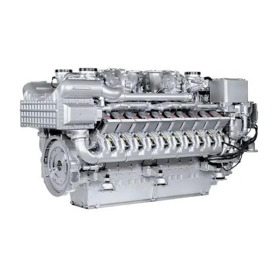
Operating Instructions Diesel engine 12 V 4000 C13, C13R, C13L 12 V 4000 C23, C23R 16 V 4000 C13, C13R, C13L 16 V 4000 C23, C23R M015695/03E... - Page 2 This Publication is protected by copyright and may not be used in any way whether in whole or in part without the prior written permission of MTU Friedrichshafen GmbH. This restriction also applies to copyright, distribution, translation, mi- crofilming and storage or processing on electronic systems including data bases and online services.
-
Page 3: Table Of Contents
7.3.1 Crankcase breather – Oil separator element replacement, diaphragm check and replacement 3 Technical Data 7.4 Running Gear 3.1 12/16 V 4000 C13/13R/13L engine data: 7.4.1 Grounding device – Carbon brush check Application group 5A, optimized fuel 7.4.2 Grounding device – Carbon brush replacement consumption 7.5 Valve Drive... - Page 4 8 Appendix A analysis 7.16 Low-Temperature Circuit 8.1 Abbreviations 7.16.1 Charge-air coolant – Level check 8.2 MTU contact persons/service partners 7.16.2 Charge-air coolant – Change 7.16.3 Draining charge-air coolant 9 Appendix B 7.16.4 Charge-air coolant – Filling 7.16.5 Charge-air coolant pump – Checking pressure 9.1 Special Tools...
-
Page 5: Safety
1 Safety 1.1 Important provisions for all products Nameplate The product is identified by nameplate, model designation or serial number and must match with the information on the title page of this manual. Nameplate, model designation or serial number can be found on the product. General information This product may pose a risk of injury or damage in the following cases: •... -
Page 6: Personnel And Organizational Requirements
1.2 Personnel and organizational requirements Organizational measures of the operator This manual must be issued to all personnel involved in operation, maintenance, repair or transporta- tion. Keep this manual handy in the vicinity of the product such that it is accessible to operating, mainte- nance, repair and transport personnel at all times. -
Page 7: Transport
Place the engine/genset on a firm, flat surface only. Make sure that the consistency and load-bearing capacity of the ground or support surface is adequate. Never set an engine down on the oil pan unless expressively authorized to do so by MTU on a case-to- case basis. -
Page 8: Crankshaft Transport Locking Device
1.4 Crankshaft transport locking device Special tools, Material, Spare parts Designation / Use Part No. Qty. Torque wrench, 10-60 Nm F30452769 Torque wrench, 60-320 Nm F30452768 Engine oil Transport locking device Note: The locking device on both ends protects the crankshaft bearings from shocks and vibration damage during engine transport. - Page 9 Screw locknut (2) onto screw (1) up to the end of the thread. The long end of holder (3) must face downwards. Push holder (3) through the plate openings (6). Note: The holders (3) must lock the flywheel only, not the ring gear. Install screw (1) into the bore of holder (1) until the holder (1) is locked in position.
-
Page 10: Crankshaft Transportation Lock - For Transport With Flange-Mounted Generator
1.5 Crankshaft transportation lock – For transport with flange- mounted generator Special tools, Material, Spare parts Designation / Use Part No. Qty. Torque wrench, 10-60 Nm F30452769 Ratchet F30027340 Engine oil Transportation lock Note: The transportation lock on the engine protects the crankshaft bearings from potential damage caused by shocks and vibration when transporting the genset. - Page 11 Turn crankshaft to bring cylinder A1 to TDC position. Check the threads on both sides of the fly- wheel (1) for ease of movement. Fit retainer (2) together with screw (4) and washer (3) through the opening in the fly- wheel housing (5).
-
Page 12: Safety Regulations For Startup And Operation
1.6 Safety regulations for startup and operation Safety regulations for startup Install the product correctly and carry out acceptance in accordance the manufacturer's specifications before putting the product into service. Before the product is put into operation for the first time, all official authorizations must be available and commissioning preconditions met. -
Page 13: Safety Regulations For Maintenance And Repair Work
1.7 Safety regulations for maintenance and repair work Safety regulations prior to maintenance and repair work Have maintenance or repair work carried out by qualified and authorized personnel only. Allow the product to cool down to less than 50°C before starting maintenance work (risk of explosion of oil vapors, fluids and lubricants, risk of burning). - Page 14 Ensure particular cleanness during maintenance and repair work on the product. After completion of maintenance and repair work, make sure that no loose objects are in/on the product (e.g. cloths and cable ties) Safety regulations after completion of maintenance and repair work Before barring, make sure that nobody is standing in the danger zone of the product.
- Page 15 Working on electrical and electronic assemblies Always obtain the permission of the person in charge before commencing maintenance and repair work or switching off any part of the electronic system required to do so. De-energize the appropriate areas prior to working on assemblies. Do not damage cabling during removal work.
-
Page 16: Fire Prevention And Environmental Protection, Fluids And Lubricants, Auxiliary Materials
The Fluids and Lubricants Specifications will be amended or supplemented as necessary. Prior to opera- tion, make sure that the latest version is used. The applicable version may be downloaded at: http:// www.mtu-online.com/mtu/mtu-valuecare/mtu-valueservice-Technische-Dokumentation. Auxiliary materials, fluids and lubricants might be hazardous goods or toxic substances.When using flu- ids, lubricants, auxiliary materials and other chemical substances, follow the safety instructions that ap- ply to the product. -
Page 17: Compressed Air
Lead • Adopt suitable measures to avoid the formation of lead dust. • Switch on extraction system. • When working with lead or lead-containing compounds, avoid direct contact to the skin and do not inhale lead vapors. • Wash hands after contact with lead or lead-containing substances. Compressed air Observe special safety precautions when working with compressed air: •... -
Page 18: Standards For Safety Notices In The Text
1.9 Standards for safety notices in the text DANGER In the event of immediate danger. Consequences: Death, serious or permanent injury. • Remedial action WARNING In the event of a situation involving potential danger. Consequences: Death, serious or permanent injury. •... -
Page 19: General Information
2 General Information 2.1 Engine side and cylinder designations Engine sides are always designated as viewed from the driving end (KS). The cylinders of the left engine side are designated "A" and those of the right side "B" (as per DIN ISO 1204). -
Page 20: Engine Layout
2.2 Engine layout Illustration is valid for 16V 4000 Cxyz engines 1 Crankcase breather 9 Intercooler 17 Engine governor 2 Air intake 10 Flywheel 18 HP fuel pump 3 Exhaust turbocharger 11 Valve gear 19 Automatic oil filter 4 Exhaust outlet 12 Lifting eye 20 Engine mounting/support 5 Air intake... -
Page 21: Sensors And Actuators - Overview
2.3 Sensors and actuators – Overview Illustration also applies to 16V 4000 Cx3 engines 1 B07 (lube oil temperature) 4 ADEC (ECU 7) 7 M8 (HP fuel pump actua- 2 Sensors for cylinder ex- 5 B34 (fuel pressure after fil- tor) haust temperature B4.1 ter) - Page 22 1 B50 (crankcase pressure) 4 B33 (fuel temperature in 7 B43 (charge-air coolant 2 B05.3 (lube oil pressure common rail) pressure) before filter) 5 B01 (camshaft speed) 8 B26 (charge-air coolant 3 B05 (lube oil pressure af- 6 B48 (fuel pressure in com- temperature) ter filter) mon rail)
- Page 23 1 Injectors Y39.11 to 4 B03 (intake air tempera- 7 B09 (charge-air tempera- Y39.16 (B-bank) ture) ture) 2 Sensors for cylinder ex- 5 B16 (coolant pressure) haust temperature B4.11 6 B10 (charge-air pressure) through B4.18 (B-bank) (optional only for 16 V) 3 B44 (turbocharger speed) The injectors are underneath the cylinder head covers of the cylinder.
- Page 24 1 B13 (crankshaft speed) 24 | General Information | M015695/03E 2013-03...
-
Page 25: Technical Data
3 Technical Data 3.1 12/16 V 4000 C13/13R/13L engine data: Application group 5A, optimized fuel consumption Explanation: DL Ref. value: Continuous power BL Ref. value: Fuel stop power A Design value G Guaranteed value R Guideline value L Limit value, up to which the engine can be operated, without change (e.g. of power setting) - Page 26 GENERAL CONDITIONS (for maximum power) Number of cylin- ders Intake depression mbar (new filter) Intake depres- mbar sion, max. Exhaust overpres- mbar sure Exhaust overpres- mbar sure, max. Fuel temperature °C at engine inlet connection Fuel temperature °C at engine inlet connection, max (w/o power re- duction)
- Page 27 COMBUSTION AIR / EXHAUST GAS Number of cylin- ders Charge-air pres- bar abs sure before cylin- Exhaust tempera- °C ture after turbo- charger COOLANT SYSTEM (HT circuit) Number of cylin- ders Coolant tempera- °C ture (at engine connection: outlet to cooling equip- ment) Coolant tempera- °C...
- Page 28 Number of cylin- ders Coolant antifreeze content, max. Charge-air tem- °C perature after in- tercooler, max. Thermostat: °C Starts to open Thermostat: Fully °C open LUBE OIL SYSTEM Number of cylin- ders Lube oil operating °C temperature be- fore engine, from Lube oil operating °C temperature be-...
- Page 29 FUEL SYSTEM Number of cylin- ders Fuel pressure at -0.1 -0.1 -0.1 -0.1 -0.1 -0.1 engine inlet con- nection, min. (when engine is starting) Fuel pressure at -0.3 -0.3 -0.3 -0.3 -0.3 -0.3 engine inlet con- nection, min. (when engine is running) Fuel pressure at engine inlet con-...
- Page 30 CAPACITIES Number of cylin- ders Engine coolant, Liters engine side (with- out cooling equip- ment) Charge-air cool- Liters ant, engine side Engine oil on ini- Liters tial filling (stand- ard oil system) (option: max. op- erating inclina- tions) Oil pan capacity Liters at dipstick mark “min.”...
- Page 31 Number of cylin- ders Engine surface dB(A) noise with attenu- ated intake noise (filter), BL, (free- field sound-pres- sure level Lp, 1m distance, ISO 6798) Engine surface dB(A) noise with attenu- ated intake noise (filter), BL (sound power level LW, ISO 6798) M015695/03E 2013-03 | Technical Data | 31...
-
Page 32: Emissions (Epa Stage 2)
3.2 12/16 V 4000 C13/13R/13L engine data: Application group 5A, optimized exhaust emissions (EPA Stage 2) Explanation: DL Ref. value: Continuous power BL Ref. value: Fuel stop power A Design value G Guaranteed value R Guideline value L Limit value, up to which the engine can be operated, without change (e.g. of power setting) - Page 33 Number of cylin- ders Exhaust overpres- mbar sure, max. Fuel temperature °C at engine inlet connection Fuel temperature °C at engine inlet connection, max (w/o power re- duction) CONSUMPTION Number of cylin- ders Lube oil con- % of B sumption after 100 h runtime (B = hourly fuel con- sumption)
- Page 34 COMBUSTION AIR / EXHAUST GAS Number of cylin- ders Charge-air pres- bar abs sure before cylin- Exhaust tempera- °C ture after turbo- charger COOLANT SYSTEM (HT circuit) Number of cylin- ders Coolant tempera- °C ture (at engine connection: outlet to cooling equip- ment) Coolant tempera- °C...
- Page 35 Number of cylin- ders Coolant antifreeze content, max. Charge-air tem- °C perature after in- tercooler, max. Thermostat: °C Starts to open Thermostat: Fully °C open LUBE OIL SYSTEM Number of cylin- ders Lube oil operating °C temperature be- fore engine, from Lube oil operating °C temperature be-...
- Page 36 FUEL SYSTEM Number of cylin- ders Fuel pressure at -0.1 -0.1 -0.1 -0.1 -0.1 -0.1 engine inlet con- nection, min. (when engine is starting) Fuel pressure at -0.3 -0.3 -0.3 -0.3 -0.3 -0.3 engine inlet con- nection, min. (when engine is running) Fuel pressure at engine inlet con-...
- Page 37 CAPACITIES Number of cylin- ders Engine coolant, Liters engine side (with- out cooling equip- ment) Charge-air cool- Liters ant, engine side Engine oil on ini- Liters tial filling (stand- ard oil system) (option: max. op- erating inclina- tions) Oil pan capacity Liters at dipstick mark “min.”...
- Page 38 Number of cylin- ders Engine surface dB(A) noise with attenu- ated intake noise (filter), BL, (free- field sound-pres- sure level Lp, 1m distance, ISO 6798) Engine surface dB(A) noise with attenu- ated intake noise (filter), BL (sound power level LW, ISO 6798) 38 | Technical Data | M015695/03E 2013-03...
-
Page 39: 12/16 V 4000 C23/23R Engine Data: Application Group 5B, Optimized Fuel Consumption
3.3 12/16 V 4000 C23/23R engine data: Application group 5B, optimized fuel consumption Explanation: DL Ref. value: Continuous power BL Ref. value: Fuel stop power A Design value G Guaranteed value R Guideline value L Limit value, up to which the engine can be operated, without change (e.g. of power setting) N Not yet defined value - Not applicable X Applicable... - Page 40 MODEL-RELATED DATA (basic design) Number of cylinders Number of cylinders Cylinder arrangement: V angle degrees Bore Stroke Cylinder displacement Liters 4.77 4.77 4.77 4.77 Total displacement Liters 57.2 57.2 76.3 76.3 Number of inlet valves per cylinder Number of exhaust valves per cylinder COMBUSTION AIR / EXHAUST GAS Number of cylinders Charge-air pressure before cylinder...
- Page 41 LUBE OIL SYSTEM Number of cylinders Lube oil operating temperature before en- °C gine, from Lube oil operating temperature before en- °C gine, to Lube oil temperature before engine, alarm R °C Lube oil temperature before engine, shut- °C down Lube oil operating pressure before engine (measurement block) Lube oil operating pressure (low idle)
- Page 42 Number of cylinders Oil pan capacity at dipstick mark “min.” Liters (standard oil system) (option: max. operat- ing inclinations) Oil pan capacity at dipstick mark “max.” Liters (standard oil system) (option: max. operat- ing inclinations) WEIGHTS (basic design, dry engine) Number of cylinders Engine dry weight (with attached standard 7000...
-
Page 43: 12/16 V 4000 C23/23R Engine Data: Application Group 5B, Optimized Exhaust Emissions (Epa Stage 2)
3.4 12/16 V 4000 C23/23R engine data: Application group 5B, optimized exhaust emissions (EPA Stage 2) Explanation: DL Ref. value: Continuous power BL Ref. value: Fuel stop power A Design value G Guaranteed value R Guideline value L Limit value, up to which the engine can be operated, without change (e.g. of power setting) N Not yet defined value - Not applicable X Applicable... - Page 44 MODEL-RELATED DATA (basic design) Number of cylinders Number of cylinders Cylinder arrangement: V angle degrees Bore Stroke Cylinder displacement Liters 4.77 4.77 4.77 4.77 Total displacement Liters 57.2 57.2 76.3 76.3 Number of inlet valves per cylinder Number of exhaust valves per cylinder COMBUSTION AIR / EXHAUST GAS Number of cylinders Charge-air pressure before cylinder...
- Page 45 LUBE OIL SYSTEM Number of cylinders Lube oil operating temperature before en- °C gine, from Lube oil operating temperature before en- °C gine, to Lube oil temperature before engine, alarm R °C Lube oil temperature before engine, shut- °C down Lube oil operating pressure before engine (measurement block) Lube oil operating pressure (low idle)
- Page 46 CAPACITIES Number of cylinders Engine coolant, engine side (without cool- Liters ing equipment) Charge-air coolant, engine side Liters Engine oil on initial filling (standard oil sys- Liters tem) (option: max. operating inclinations) Oil pan capacity at dipstick mark “min.” Liters (standard oil system) (option: max.
-
Page 47: Firing Order
3.5 Firing order Firing order Num- Firing order ber of cylin- ders A1-B4-A4-A2-B3-A3-B2-B1 A1-B5-A5-B3-A3-B6-A6-B2-A2-B4-A4-B1 16 V A1-A7-B4-B6-A4-B8-A2-A8-B3-B5-A3-A5-B2-A6-B1-B7 20 V A1-B5-A8-B7-A5-B2-A7-B10-A2-B3-A10-B6-A3-B4-A6-B9-A4-B1-A9-B8 M015695/03E 2013-03 | Technical Data | 47... -
Page 48: Main Engine Dimensions
3.6 Main engine dimensions Main engine dimensions Length (A) 12V approx. 2810 mm Length (A) 16V approx. 3280 mm Width (B) 12V, 16V approx. 1585 mm Height (C) 12V, 16V approx. 2027 mm 48 | Technical Data | M015695/03E 2013-03... -
Page 49: Operation
4 Operation 4.1 Preparations for recommissioning the engine after extended out-of-service periods (>3 months) Preconditions ☑Engine shut down and secured against being restarted. ☑MTU Corrosion-proofing and Reproofing Regulations (A001070/..) are available. Recommissioning after long out-of-service periods (>3 months) Item Action Engine Remove corrosion-proofing (→... -
Page 50: Putting The Engine Into Operation After Scheduled Out-Of-Service-Period
4.2 Putting the engine into operation after scheduled out-of- service-period Preconditions ☑Engine is stopped and starting disabled. Startup Item Action Lube oil system Check engine oil level (→ Page 110). Coolant circuit Check engine coolant level (→ Page 122); Check charge-air coolant level (→ Page 132). Coolant circuit Preheat coolant with coolant preheating unit (if applicable). -
Page 51: Starting The Engine In Manual Mode
4.3 Starting the engine in manual mode Preconditions ☑Engine is not under load. ☑External start interlock is not activated. DANGER Unguarded rotating and moving engine components. Risk of serious injury – danger to life! • Before barring or starting the engine, make sure that nobody is in the danger zone. WARNING Engine noise above 85 dB (A). -
Page 52: Stopping The Engine In Manual Mode
4.4 Stopping the engine in manual mode Preconditions ☑Engine is not under load. ☑Engine is running in manual mode. CAUTION Stopping the engine when it is running at full load causes extreme stress to the engine. Risk of overheating, damage to components! •... -
Page 53: After Shutting Down The Engine
4.5 After shutting down the engine Preconditions ☑MTU Corrosion-proofing and Reproofing Regulations (A001070/..) are available. After shutting down the engine Item Action Coolant system Drain coolant (→ Page 124), (→ Page 134), if: • freezing temperatures are expected and the engine is to remain out of service for an extended period, but engine coolant has no antifreeze additive;... -
Page 54: Plant Cleaning
4.6 Plant cleaning Preconditions ☑Engine is stopped and starting disabled. ☑Operating voltage is not present. Special tools, Material, Spare parts Designation / Use Part No. Qty. Steam jet cleaner Cleaner (Hakupur 312) 30390 WARNING Compressed air Risk of injury! • Do not direct compressed-air jet at persons. •... -
Page 55: Maintenance
5 Maintenance 5.1 Maintenance task reference table [QL1] The maintenance tasks and intervals for this product are defined in the Maintenance Schedule. The Maintenance Schedule is a stand-alone publication. The task numbers in this table provide reference to the maintenance tasks specified in the Maintenance Schedule. -
Page 56: Troubleshooting
6 Troubleshooting 6.1 Troubleshooting Engine does not turn over when starter is operated Component Cause Action Battery Discharged or defective Charge or replace (see manufacturer's documentation). Cable connections defective Check if cable connections are properly secured (see manufacturer's documen- tation). Starter Engine wiring or starter faulty Check if cable connections are properly... - Page 57 Defective Notify Service. Charge air temperature too high Component Cause Action Engine coolant Incorrect coolant concentration Check (MTU test kit). Intercooler Dirty Notify Service. Engine room Air-intake temperature too high Check fans and air intake/exhaust pipes. Charge-air pressure too low...
- Page 58 Component Cause Action Drain water from fuel prefilter. Intercooler Leaking Notify Service. 58 | Troubleshooting | M015695/03E 2013-03...
-
Page 59: Fault Messages Of The Engine Governor Adec (Ecu 7) For Series 4000 C&I Engines
6.2 Fault messages of the engine governor ADEC (ECU 7) for series 4000 C&I engines The fault code numbers are generated by the Engine Control Unit an transmitted to the display. The fault code (1) comprises three digits. Fault messages can also be caused by faulty sensors/actuators. Contact Service to have sensors/ actuators checked and replaced as necessary if the troubleshooting measures listed in the table below prove unsuccessful. - Page 60 Related parameter Fault code No. Full designation Meaning Action 1. Check oil level, top up as necessa- ry(→ Page 110). Oil pressure too low 2. Attempt to re- (2nd limit value), automatic start engine 2.0100.92 SS P-Lube Oil engine shutdown. (→...
- Page 61 Related parameter Fault code No. Full designation Meaning Action Alarm configuration limit val- ue 1; preliminary warning: Speed of secondary turbo- 1. Reduce power. 2.3013.93 HI ETC2 Overspeed charger too high. 2. Contact Service. Alarm configuration limit val- ue 2; main warning: Speed of secondary turbocharger too high.
- Page 62 Related parameter Fault code No. Full designation Meaning Action Flush fuel prefil- ter.Replace fuel prefilter filter ele- ment. Replace fuel filter (→ Page 104). Coolant temperature too 2.0120.93 HI T-Coolant high (1st limit value). Reduce power. 1. Allow the engine to cool down;...
- Page 63 Related parameter Fault code No. Full designation Meaning Action Alarm configuration limit val- ue; Starter speed was not at- tained; Termination of start- ing sequence; Starter rotates too slowly or does not rotate 2.1090.92 SS No Starter Speed at all. Contact Service.
- Page 64 Related parameter Fault code No. Full designation Meaning Action Contact Serv- Supply voltage of tempera- ice.Check sen- L1 TE BUFFER TEST ture sensors faulty. sors;Replace ECU. Contact Serv- Supply voltage of tempera- ice.Check sen- TE BUF. ECU DEFECT ture sensors faulty. sors;Replace ECU.
- Page 65 Related parameter Fault code No. Full designation Meaning Action Alarm configuration; The se- lected CAN mode initializes communication by means of the PU data module. Howev- er, the necessary PU data module is not present or is 2.0500.68 AL CAN No PU-Data invalid.
- Page 66 Related parameter Fault code No. Full designation Meaning Action 1. Check cabling. Sensor B33 defective (fuel 2. Replace if neces- 1.8004.57 SD T-Fuel temperature). sary. 1. Check cabling. Sensor B09 faulty (charge-air 2. Replace if neces- 1.8004.57 SD T-Charge Air temperature) A side.
- Page 67 Related parameter Fault code No. Full designation Meaning Action 1. Check sensor and wiring. 2. Replace if neces- sary. Error cleared after Sensor F25 faulty (lube oil restarting the en- 1.8004.58 SD Diff Lube Oil differential pressure). gine. 1. Check sensor and wiring.
- Page 68 Related parameter Fault code No. Full designation Meaning Action Sensor fault (ECU operating SD ECU Supply Voltage voltage). Replace ECU. 2.8006589 1. Check cabling. 2. Check speed set- 2.8006.58 SD Speed Setting External speed setting faulty. ting. Check cabling, re- SD alarm configuration;...
- Page 69 Related parameter Fault code No. Full designation Meaning Action 1.8004.51 1.8004.51 1.8004.51 1.8004.51 1.8004.51 1.8004.51 Wiring bank 1 (solenoid 1. Check solenoid WIRING CYLINDER(A1- valve 1) ... Wiring bank 1 valve. 1.8004.52 A10) (solenoid valve 10) 2. Contact Service. 1.8004.52 1.8004.52 1.8004.52 1.8004.52...
- Page 70 Related parameter Fault code No. Full designation Meaning Action 1.8004.53 1.8004.53 1.8004.53 1.8004.53 Open Load Bank 1 (solenoid 1. Check solenoid OPEN_LOAD CYL.(A1- valve 1) ... Open Load Bank 1 valve. 1.8004.54 A10) (solenoid valve 10) 2. Contact Service. 1.8004.54 1.8004.54 1.8004.54 1.8004.54...
- Page 71 Related parameter Fault code No. Full designation Meaning Action 1.8004.55 1.8004.55 Alarm configuration; Internal electronic fault (electronics possibly faulty: start ITS).Check additional mes- sages if ITS indicates diagno- 1. Check solenoid AL Injector Power Stage sis "Electronics OK" (e.g. ca- valve cabling.
- Page 72 Related parameter Fault code No. Full designation Meaning Action Alarm configuration; Short circuit or wire break on tran- sistor output, plant-side 2 Check cabling to 2.8006.63 AL Wiring TOP 2 (TOP 2). plant. Alarm configuration; Short circuit or wire break on tran- sistor output, plant-side 3 Check cabling to 2.8006.64...
- Page 73 Related parameter Fault code No. Full designation Meaning Action Alarm configuration; Line dis- 1. Check cabling. ruption on digital input 3; Ca- 2. Contact Service.; AL Open Load Digital In- bling faulty or no resistance Check input of tar- 2.8006.62 put 3 over switch.
- Page 74 Related parameter Fault code No. Full designation Meaning Action Alarm configuration limit val- ue 1; Preliminary warning: Coolant pressure in inter- Top up coolant 2.0107.92 LO P-Coolant Intercooler cooler too low. (→ Page 135). Alarm configuration limit val- ue 2; Main warning: Coolant pressure in intercooler too Top up coolant 2.0107.92...
- Page 75 Related parameter Fault code No. Full designation Meaning Action Alarm configuration limit val- ue 2; Main warning: Charge- 2.0103.93 SS P-Charge Air air pressure too high. Contact Service. Check signal trans- mitter and cabling, replace as necessa- SD alarm configuration; Input signal for initial/final torque Error cleared after faulty;...
- Page 76 Related parameter Fault code No. Full designation Meaning Action Check pressure transmitter and ca- SD alarm configuration; Ana- bling, replace as log input signal for Aux 2 necessary.Error pressure faulty; Short circuit cleared after re- 1.8004.58 SD P-AUX 2 or wire break starting the engine.
- Page 77 Related parameter Fault code No. Full designation Meaning Action Alarm configuration; Initiali- zation error of crash record- Check settings with 1.8010.00 AL Crash Rec. Init. Error DiaSys. Alarm configuration; Com- AL Comb. Alarm Yellow bined alarm YELLOW from Note further fault 2.8006.00 (Plant) plant.
-
Page 78: Task Description
7 Task Description 7.1 Engine 7.1.1 Cranking engine manually Preconditions ☑Engine shut down and secured against being restarted. Special tools, Material, Spare parts Designation / Use Part No. Qty. Cranking tool F6555766 Cranking tool F6783293 Adapter F6558528 Ratchet with extension F30006212 DANGER Unguarded rotating and moving engine components. - Page 79 Cranking engine manually (tool mounted underneath) Remove grounding device or guard plate. Engage cranking tool (2) in ring gear (1) and mount on flywheel housing. • For 12/16V engines, use cranking tool F6555766 with adapter F6558528. • For 20V engines, use cranking tool F6783293.
-
Page 80: Engine - Barring With Starting System
7.1.2 Engine – Barring with starting system DANGER Unguarded rotating and moving engine components. Risk of serious injury – danger to life! • Before barring or starting the engine, ensure that nobody is in the danger zone. • After working on the engine, check that all protective devices have been reinstalled and all tools removed from the engine. -
Page 81: Cylinder Liner
7.2 Cylinder Liner 7.2.1 Cylinder liner – Endoscopic examination Preconditions ☑Engine is stopped and starting disabled Special tools, Material, Spare parts Designation / Use Part No. Qty. Barring device F6555766 Ratchet with extension F30006212 Endoscope Y20097353 Preparatory steps Remove cylinder head cover (→ Page 95). Remove injector (→... - Page 82 Compile endoscopy report using the table. Use technical terms for description of the liner surface (→ Page 83). Depending on findings: • Do not take any action or • carry out a further endoscopic examination as part of maintenance work or •...
-
Page 83: Instructions And Comments On Endoscopic And Visual Examination Of Cylinder Liners
7.2.2 Instructions and comments on endoscopic and visual examination of cylinder liners Terms used for endoscopic examination Use the terms listed below to describe the condition of the cylinder-liner surface in the endoscopic ex- amination report. Findings Measure Light scoring Minor dirt scores can occur during the assembly of a new engine (honing prod- ucts, particles, broken-off burrs). - Page 84 Findings Measure Liners with heat discoloration starting in the TDC-ring 1 have to be replaced. Seizures, Seizure marks Seizure marks are of irregular circumferential length and depth. Can be caused by either the piston skirt or the piston crown. Material deposits on the liner (smears) show heavy discoloration and scoring.
-
Page 85: Crankcase Breather
7.3 Crankcase Breather 7.3.1 Crankcase breather – Oil separator element replacement, diaphragm check and replacement Preconditions ☑Engine is stopped and starting disabled. Special tools, Material, Spare parts Designation / Use Part No. Qty. Torque wrench, 6-50 Nm F30027336 Ratchet F30027340 Engine oil Filter element (→... - Page 86 Checking diaphragm Remove cover (4). Remove spring (5), gasket (2) and dia- phragm (3). Check diaphragm (3) for damage, fit new diaphragm if used one is damaged. Install diaphragm (3) on housing (1). Install new seal (2) and spring (5) together with cover (4).
-
Page 87: Running Gear
7.4 Running Gear 7.4.1 Grounding device – Carbon brush check Preconditions ☑Engine is stopped and starting disabled. Special tools, Material, Spare parts Designation / Use Part No. Qty. Cold cleaner (Hakutex 60) 50602 Carbon brush (→ Spare Parts Catalog) WARNING Compressed air Risk of injury! •... - Page 88 Cleaning running surface on adapter Clean running surface of carbon brushes on adapter with cold cleaner. Remove stubborn deposits with soft brush. Blow out adapter with compressed air. Installing grounding device Check mounting surface on flywheel housing for cleanness. Install grounding device on flywheel housing and secure with screws. 88 | Task Description | M015695/03E 2013-03...
-
Page 89: Grounding Device - Carbon Brush Replacement
7.4.2 Grounding device – Carbon brush replacement Preconditions ☑Engine shut down and starting disabled. Special tools, Material, Spare parts Designation / Use Part No. Qty. Loctite 270 40083 Carbon brush (→ Spare Parts Catalog) Replace carbon brush Loosen screw (5). Disconnect cable (6) from screw (5). -
Page 90: Valve Drive
7.5 Valve Drive 7.5.1 Valve gear – Lubrication Preconditions ☑Engine is stopped and starting disabled. Special tools, Material, Spare parts Designation / Use Part No. Qty. Engine oil Valve gear – Lubrication Remove cylinder head covers (→ Page 95). Fill oil chambers of valve bridges with oil. Fill oil chambers of rocker arms and adjust- ing screws with oil. -
Page 91: Valve Clearance - Check And Adjustment
7.5.2 Valve clearance – Check and adjustment Preconditions ☑Engine shut down and starting disabled. ☑Engine coolant temperature is max. 40 °C. ☑Valves are closed. Special tools, Material, Spare parts Designation / Use Part No. Qty. Feeler gauge Y20098771 Torque wrench, 60-320 Nm F30452768 Box wrench socket, 24 mm F30039526... - Page 92 Rotate crankshaft with barring device in di- rection of engine rotation until the "OT-A1" marking and pointer are aligned. Diagram for 8V engines (two crankshaft positions) Diagram for 12V engines (two crankshaft positions) 92 | Task Description | M015695/03E 2013-03...
- Page 93 Diagram for 16V engines (two crankshaft positions) Diagram for 20V engines (two crankshaft positions) Checking valve clearance at two crankshaft positions Check TDC position of piston in cylinder A1: • If the rocker arms are unloaded on cylinder A1, the piston is in firing TDC. •...
-
Page 94: Adjusting Valve Clearance
Adjusting valve clearance Release locknut (1). Insert feeler gauge (3) between valve bridge and rocker arm. Use Allen key to set adjusting screw (2) so that the specified valve clearance is estab- lished. Feeler gauge (3) must just pass through gap. -
Page 95: Cylinder Head Cover - Removal And Installation
7.5.3 Cylinder head cover – Removal and installation Preconditions ☑Engine is stopped and starting disabled. Special tools, Material, Spare parts Designation / Use Part No. Qty. Grease (Kluthe Hakuform 30-10/Emulgier) X00029933 O-ring (→ Spare Parts Catalog) Removing cylinder head cover Clean very dirty cylinder head covers (1) prior to removal. -
Page 96: Injection Pump / Hp Pump
7.6 Injection Pump / HP Pump 7.6.1 HP pump – Filling with engine oil Preconditions ☑Engine is stopped and starting disabled. Special tools, Material, Spare parts Designation / Use Part No. Qty. Engine oil WARNING Fuels are combustible. Risk of fire and explosion! •... -
Page 97: Injection Valve / Injector
7.7 Injection Valve / Injector 7.7.1 Injector – Replacement Special tools, Material, Spare parts Designation / Use Part No. Qty. Injector (→ Spare Parts Catalog) Replacing injector Remove injector and install new injector (→ Page 98). M015695/03E 2013-03 | Task Description | 97... -
Page 98: Injector - Removal And Installation
7.7.2 Injector – Removal and installation Preconditions ☑Engine is stopped and starting disabled. Special tools, Material, Spare parts Designation / Use Part No. Qty. Installation/removal tool F6789889 Milling cutter F30452739 Torque wrench, 0.5-5 Nm 0015384230 Torque wrench, 10-60 Nm F30452769 Ratchet F30027340 Torque wrench, 60-320 Nm... - Page 99 Remove HP fuel line (4). Remove return line (5). Note: The injector accumulator will be emptied when removing the adapter. Remove adapter (3). Remove screw (2) and take off hold-down clamp (1). Install installation/removal tool on cylinder head. Remove injector with installation/removal tool.
-
Page 100: Installing Injector
Installing injector Remove plug before installing the injec- tor. (Do not remove the plug from the HP line before installing the adapter.) Coat injector with assembly paste at the seat of the nozzle clamping nut. Fit new sealing ring (included in the scope of supply of the injector) with grease on in- jector, observe installation position of seal- ing ring. - Page 101 Coat screw head mating face (2) and thread with engine oil. Fit hold-down clamp (1) in the correct position and use torque wrench to tighten screw (2) to the speci- fied initial tightening torque. Name Size Type Lubricant Value/Standard Screw Preload torque (Engine oil) 5 Nm to 10 Nm...
- Page 102 Mount double-walled HP line (5) and use torque wrench to tighten to the specified torque. Tightening sequence: 1 Adapter (4) 2 Rail (6) Name Size Type Lubricant Value/Standard Union nut / thrust Tightening torque 40 Nm + 5 Nm screw Fit cable connector onto injector.
-
Page 103: Fuel System
7.8 Fuel System 7.8.1 Fuel system – Venting Preconditions ☑Engine is stopped and starting disabled. Special tools, Material, Spare parts Designation / Use Part No. Qty. Diesel fuel WARNING Fuels are combustible. Risk of fire and explosion! • Avoid open flames, electrical sparks and ignition sources. •... -
Page 104: Fuel Filter
7.9 Fuel Filter 7.9.1 Fuel filter – Replacement Preconditions ☑Engine is stopped and starting disabled. Special tools, Material, Spare parts Designation / Use Part No. Qty. Filter wrench F30379104 Engine oil Easy-change filter (→ Spare Parts Catalog) WARNING Fuels are combustible. Risk of fire and explosion! •... -
Page 105: Draining Fuel Prefilter
7.9.2 Draining fuel prefilter Preconditions ☑Engine shut down and secured against being restarted. Special tools, Material, Spare parts Designation / Use Part No. Qty. Diesel fuel WARNING Fuels are combustible. Risk of fire and explosion! • Avoid open flames, electrical sparks and ignition sources. •... -
Page 106: Fuel Prefilter - Draining
7.9.3 Fuel prefilter – Draining Preconditions ☑Engine is stopped and starting disabled. Special tools, Material, Spare parts Designation / Use Part No. Qty. Diesel fuel WARNING Fuels are combustible. Risk of fire and explosion! • Avoid open flames, electrical sparks and ignition sources. •... -
Page 107: Charge-Air Cooling
7.10 Charge-Air Cooling 7.10.1 Intercooler – Checking condensate drain for coolant discharge and obstructions DANGER Unguarded rotating and moving engine components. Risk of serious injury – danger to life! • Take special care when working on a running engine. WARNING Engine noise above 85 dB (A). -
Page 108: Air Intake
7.11 Air Intake 7.11.1 Service indicator – Signal ring position check Preconditions ☑Engine is stopped and starting disabled. Checking signal ring position If the signal ring is completely visible in the control window (2), replace air filter. After installation of new filter, press reset button (1). -
Page 109: Starting Equipment
7.12 Starting Equipment 7.12.1 Starter – Condition check Preconditions ☑Engine is stopped and starting disabled. Checking starter condition Check securing screws of starter for secure seating and tighten if required. Check wiring (→ Page 149). M015695/03E 2013-03 | Task Description | 109... -
Page 110: Lube Oil System, Lube Oil Circuit
7.13 Lube Oil System, Lube Oil Circuit 7.13.1 Checking engine oil level Checking oil level before start- ing engine Withdraw oil dipstick from guide tube and wipe it clean. Insert dipstick into guide tube and push fully home, withdraw after approx. 10 sec- onds. -
Page 111: Checking Engine Oil Level
7.13.2 Checking engine oil level Preconditions ☑Engine shut down and secured against being restarted. Checking engine oil level at oil sight glass The oil level (2) can be checked visually in advance at the oil sight glass (1). A correct reading of the engine oil level is only possible with the oil dipstick (→... -
Page 112: Engine Oil – Change
7.13.3 Engine oil – Change Preconditions ☑Engine shut down and starting disabled. ☑Engine is at operating temperature. ☑MTU Fluids and Lubricants Specifications (A001061/..) are available. Special tools, Material, Spare parts Designation / Use Part No. Qty. Torque wrench, 40-200Nm F30027337... - Page 113 Tighten drain screws (2) and (3) with torque wrench to the specified torque. Name Size Type Lubricant Value/Standard Screw M26 x 1.5 Tightening torque (Engine oil) 100Nm +10Nm Filling with new engine oil Open cover on filler neck. Pour oil in at filler neck up to "max." mark at oil dipstick.
-
Page 114: Engine Oil – Sample Extraction And Analysis
7.13.4 Engine oil – Sample extraction and analysis Preconditions ☑MTU Fluids and Lubricants Specifications (A001061/..) are available. Special tools, Material, Spare parts Designation / Use Part No. Qty. MTU test kit 5605892099/00 DANGER Unguarded rotating and moving engine components. Risk of serious injury – danger to life! •... -
Page 115: Oil Filtration / Cooling
7.14 Oil Filtration / Cooling 7.14.1 Automatic oil filter – Oil filter candles replacement Preconditions ☑Engine is stopped and starting disabled. Special tools, Material, Spare parts Designation / Use Part No. Qty. Grease (Kluthe Hakuform 30-10/Emulgier) X00058060 Engine oil O-ring (→... - Page 116 Pull out oil filter element (1). Remove O-ring. Remove screw (2). Pull out plastic spinner (1) with spring. Remove nut (3). Take off spring washer and washer. Remove screw (4). Remove flushing arm (5) from screen plate (6). Turn filter element by 180° and use appro- priate tool to push out filter candles (1).
- Page 117 Installing oil filter candles Install in reverse order of removal. Additionally, the following instructions are to be observed: • Replace all seals with new parts • Coat O-rings with grease • Insert O-rings in grooves • Pay attention to installation position of fillister-head screw to slot in shaft. M015695/03E 2013-03 | Task Description | 117...
-
Page 118: Oil Indicator Filter – Cleaning And Check
7.14.2 Oil indicator filter – Cleaning and check Preconditions ☑Engine is stopped and starting disabled. Special tools, Material, Spare parts Designation / Use Part No. Qty. Cleaner (Snow-White 11-0) 40460 Cleaner (Hakupur 312) 30390 Engine oil Strainer (→ Spare Parts Catalog) Square-section ring (→... - Page 119 Checking strainer Item Findings Action • Clean Strainer Metallic residues • Monitor engine operation • Check strainer daily • Contact Service. Strainer Damaged Fit new part Square-section ring Damaged Fit new part O-ring Damaged Fit new part Cleaning strainer Wash strainer (5) with cleaner. Remove stubborn deposits with soft brush.
- Page 120 7.14.3 Centrifugal oil filter – Cleaning and filter-sleeve replacement Preconditions ☑Engine is stopped and starting disabled. Special tools, Material, Spare parts Designation / Use Part No. Qty. Torque wrench, 6-50 Nm F30027336 Cold cleaner (Hakutex 60) X00056750 Filter sleeve (→ Spare Parts Catalog) Sealing ring (→...
- Page 121 Centrifugal oil filter – Cleaning and filter-sleeve replacement Remove clamp (14). Release cover screw (2) and take off cov- er (1). Carefully lift rotor (11), allow oil to drain and remove from housing. Holding the rotor (11) firmly, release rotor cover nut (3).
-
Page 122: Circuit
7.15 Coolant Circuit, General, High-Temperature Circuit 7.15.1 Engine coolant – Level check Preconditions ☑Engine is stopped and starting disabled. ☑MTU Fluids and Lubricants Specifications (A001061/..) are available. WARNING Coolant is hot and under pressure. Risk of injury and scalding! • Let the engine cool down. -
Page 123: Engine Coolant – Change
7.15.2 Engine coolant – Change Special tools, Material, Spare parts Designation / Use Part No. Qty. Coolant Engine coolant – Change Drain engine coolant (→ Page 124). Fill with engine coolant (→ Page 126). M015695/03E 2013-03 | Task Description | 123... -
Page 124: Draining Engine Coolant
7.15.3 Draining engine coolant Preconditions ☑Engine shut down and secured against being restarted. WARNING Coolant is hot and under pressure. Risk of injury and scalding! • Let the engine cool down. • Wear protective clothing, gloves, and goggles / safety mask. Preparatory steps Have a suitable container ready to catch the coolant. - Page 125 Open the drainage point on the main PTO end of the crankcase, on the left or right side (arrowed) and drain off the engine coolant. Close off all open drain points. Place pressure cap on filler neck and close. Concluding operations Switch on preheater.
-
Page 126: Engine Coolant – Filling
7.15.4 Engine coolant – Filling Preconditions ☑Engine is stopped and starting disabled. ☑MTU Fluids and Lubricants Specifications (A001061/..) are available. Special tools, Material, Spare parts Designation / Use Part No. Qty. Engine coolant WARNING Coolant is hot and under pressure. - Page 127 Filling with coolant using a pump Connect a suitable pump with a hose to drain valve at main PTO end (arrowed). Open vent points on distributor, oil heat ex- changer and exhaust turbochargers (ar- rows). Open drain valve and pump coolant into en- gine at 0.5 bar minimum.
- Page 128 Alternatively: Filling with cool- ant through filler neck Open vent points on distributor, oil heat ex- changer and exhaust turbochargers (ar- rows). Add coolant to expansion tank until the coolant level at top edge of filler neck re- mains constant. When coolant emerges from the vent points, close vent points one by one, pro- ceeding from the lowest point upwards.
- Page 129 7.15.5 Engine coolant pump – Checking pressure relief port DANGER Unguarded rotating and moving engine components. Risk of serious injury – danger to life! • Take special care when working on a running engine. WARNING Engine noise above 85 dB (A). Risk of damage to hearing! •...
-
Page 130: Engine Coolant Filter – Replacement
7.15.6 Engine coolant filter – Replacement Preconditions ☑Engine is stopped and starting disabled. Special tools, Material, Spare parts Designation / Use Part No. Qty. Filter wrench F30379104 Engine oil Coolant filter (→ Spare Parts Catalog) WARNING Coolant is hot and under pressure. Risk of injury and scalding! •... - Page 131 7.15.7 Engine coolant – Sample extraction and analysis Preconditions ☑MTU Fluids and Lubricants Specifications (A001061/..) are available. Special tools, Material, Spare parts Designation / Use Part No. Qty. MTU test kit 5605892099/00 DANGER Unguarded rotating and moving engine components. Risk of serious injury – danger to life! •...
-
Page 132: Low-Temperature Circuit
7.16 Low-Temperature Circuit 7.16.1 Charge-air coolant – Level check Preconditions ☑Engine is stopped and starting disabled. ☑MTU Fluids and Lubricants Specifications (A001061/..) are available. WARNING Coolant is hot and under pressure. Risk of injury and scalding! • Let the engine cool down. -
Page 133: Charge-Air Coolant – Change
7.16.2 Charge-air coolant – Change Special tools, Material, Spare parts Designation / Use Part No. Qty. Coolant Charge-air coolant – Change Drain charge-air coolant (→ Page 134). Fill with charge-air coolant (→ Page 135). M015695/03E 2013-03 | Task Description | 133... -
Page 134: Draining Charge-Air Coolant
7.16.3 Draining charge-air coolant Preconditions ☑Engine shut down and secured against being restarted. Special tools, Material, Spare parts Designation / Use Part No. Qty. Sealing ring (→ Spare Parts Catalog) WARNING Coolant is hot and under pressure. Risk of injury and scalding! •... -
Page 135: Charge-Air Coolant – Filling
7.16.4 Charge-air coolant – Filling Preconditions ☑Engine shut down and starting disabled. ☑MTU Fluids and Lubricants Specifications (A001061/..) are available. Special tools, Material, Spare parts Designation / Use Part No. Qty. Charge-air coolant WARNING Coolant is hot and under pressure. - Page 136 Filling with charge-air coolant using pump Connect appropriate pump with hose to a drain valve (arrow) or at the lowest point between engine and cooler. Open vent point on charge-air cooler (ar- row). Open drain valve and pump coolant into en- gine at 0.5 bar minimum.
- Page 137 Alternatively: Filling with cool- ant through filler neck Open vent point on charge-air cooler (ar- row). Top up engine coolant via filler neck on coolant expansion tank until coolant level remains constant in sight glass at max. mark. When coolant emerges from the vent point, close vent point.
- Page 138 7.16.5 Charge-air coolant pump – Checking pressure relief port DANGER Unguarded rotating and moving engine components. Risk of serious injury – danger to life! • Take special care when working on a running engine. WARNING Engine noise above 85 dB (A). Risk of damage to hearing! •...
-
Page 139: Belt Drive
7.17 Belt Drive 7.17.1 Drive belt – Condition check Preconditions ☑Engine is stopped and starting disabled. ☑Guard is removed. Drive belt – Condition check Item Findings Action Drive belt A Singular cracks None Drive belt Belt is oily, shows signs of over- Replace (→... -
Page 140: Battery-Charging Generator
7.18 Battery-Charging Generator 7.18.1 Alternator – Removing and refitting Preconditions ☑Engine shut down and secured against being restarted. Special tools, Material, Spare parts Designation / Use Part No. Qty. Torque wrench, 20-100 Nm F30026582 Ratchet adapter F30027340 WARNING Heavy object. Risk of crushing! •... - Page 141 Unscrew bolts (arrowed). Remove alternator (1). Clean alternator (1) thoroughly (→ Page 142). Refit alternator (1) in reverse order of re- moval. Tensioning drive belt Fit drive belt. Slacken bolt (2) by half a turn. Result: Belt tensioner moves against the drive belt and tensions it.
-
Page 142: Battery-Charging Generator – Check
7.18.2 Battery-charging generator – Check Preconditions ☑Engine shut down and starting disabled. WARNING Compressed air Risk of injury! • Do not direct compressed-air jet at persons. • Wear protective goggles / safety mask and ear protectors. Checking battery-charging generator Item Findings Measure Ventilation area (arrow) - Page 143 7.18.3 Battery-charging generator drive – Drive belt tension adjustment Preconditions ☑Engine is stopped and starting disabled. Special tools, Material, Spare parts Designation / Use Part No. Qty. Torque wrench, 60-320 Nm F30452768 Ratchet F30027341 Torque wrench, 10-60 Nm F30452769 Ratchet F30027340 WARNING Spring/circlip/tensioning roller preload.
- Page 144 7.18.4 Battery-charging generator – Drive belt and belt tensioner replacement Preconditions ☑Engine is stopped and starting disabled. Special tools, Material, Spare parts Designation / Use Part No. Qty. Torque wrench, 20-100Nm F30026582 Ratchet adapter F30027340 Drive belt (→ Spare Parts Catalog) Belt tensioner (→...
- Page 145 Install protective cover. Readjust belt tension after 30 minutes and again after 8 hours engine runtime (→ Page 143). M015695/03E 2013-03 | Task Description | 145...
-
Page 146: Fan Drive
Hold measuring tip of belt tension tester over belt drive. Tap drive belt (arrow) with a suitable tool. Hold belt tension tester over belt drive until the measured value is indicated. Initial assembly at MTU Initial operation with fan Re-tensioning None 60 Hz ±1 Hz 52 Hz ±1 Hz... - Page 147 Hold measuring tip of belt tension tester over belt drive. Tap drive belt (arrow) with a suitable tool. Hold belt tension tester over belt drive until the measured value is indicated. Initial assembly at MTU Initial operation with fan Re-tensioning 36 Hz ±5 Hz 49 Hz ±2 Hz...
-
Page 148: Fan Drive – Drive Belt Replacement
7.19.2 Fan drive – Drive belt replacement Preconditions ☑Engine is stopped and starting disabled. Special tools, Material, Spare parts Designation / Use Part No. Qty. Drive belt (→ Spare Parts Catalog) Preparatory steps Remove protective cover. Remove fan. Replacing drive belt Release screws (2). -
Page 149: Wiring (General) For Engine/Gearbox/Unit
7.20 Wiring (General) for Engine/Gearbox/Unit 7.20.1 Engine wiring – Check Preconditions ☑Engine is stopped and starting disabled. Special tools, Material, Spare parts Designation / Use Part No. Qty. Isopropyl alcohol X00058037 Engine wiring – Check Check securing screws of cable clamps on engine and tighten loose threaded connections. Ensure that cables are fixed in their clamps and cannot swing freely. -
Page 150: Accessories For (Electronic) Engine Governor / Control System
7.21 Accessories for (Electronic) Engine Governor / Control System 7.21.1 Engine governor and connectors – Cleaning Preconditions ☑Engine is stopped and starting disabled. Special tools, Material, Spare parts Designation / Use Part No. Qty. Isopropyl alcohol X00058037 Note: Always use test connectors to enter the connectors. Never use test leads for this purpose.Otherwise the contacts could be bent. -
Page 151: Engine Governor Plug Connections – Check
7.21.2 Engine governor plug connections – Check Preconditions ☑Engine is stopped and starting disabled. Note: Always use test plugs to check the connections. Never use test leads. Otherwise, the contacts might be bent. Engine governor plug connections – Check Check all plug connections for secure seating. Latch plugs if loose. -
Page 152: Abbreviations
Abgasturbolader Exhaust turbocharger Backup Data Module Data backup module Baureihe Series Betriebsstoffvorschrift Fluids and Lubricants Specifications, MTU Publica- tion No. A01061/.. Controller Area Network Data bus system, bus standard CaPoS Capacitor Power System Starting system based on capacitors Calibration Drift Compensation Resets the drift correction with DiaSys®... - Page 153 Abbre- Meaning Explanation viation Initial Injector Equalization Input of the injector code with DiaSys® in engine governor to ensure optimum emission and consump- tion behavior International Organization for Standardiza- International umbrella organization for all national tion standardization institutes Integrated Test System Kraftgegenseite Engine free end in accordance with DIN ISO 1204 Kraftseite...
-
Page 154: Mtu Contact Persons/Service Partners
Local support Experienced and qualified specialists place their knowledge and expertise at your disposal. For locally available support, go to the MTU Internet site: http://www.mtu-online.com 24h hotline With our 24h hotline and the outstanding flexibility of our service staff, we are always ready to assist you –... -
Page 155: Appendix B 9.1 Special Tools
9 Appendix B 9.1 Special Tools Adapter Part No.: F6558528 Qty.: Used in: 7.1.1 Cranking engine manually (→ Page 78) Barring device Part No.: F6555766 Qty.: Used in: 7.2.1 Cylinder liner – Endoscopic examination (→ Page 81) Box wrench socket, 24 mm Part No.: F30039526 Qty.:... - Page 156 Cranking tool Part No.: F6555766 Qty.: Used in: 7.1.1 Cranking engine manually (→ Page 78) Cranking tool Part No.: F6783293 Qty.: Used in: 7.1.1 Cranking engine manually (→ Page 78) Endoscope Part No.: Y20097353 Qty.: Used in: 7.2.1 Cylinder liner – Endoscopic examination (→...
- Page 157 7.7.2 Injector – Removal and installation (→ Page 98) Milling cutter Part No.: F30452739 Qty.: Used in: 7.7.2 Injector – Removal and installation (→ Page 98) MTU test kit Part No.: 5605892099/00 Qty.: Used in: 7.13.4 Engine oil – Sample extraction and analysis (→ Page 114) Qty.:...
- Page 158 Optibell 2 belt tension tester Part No.: Y4345711 Qty.: Used in: 7.19.1 Fan drive – Drive belt tension check / adjust- ment (→ Page 146) Ratchet Part No.: F30027340 Qty.: Used in: 1.5 Crankshaft transportation lock – For transport with flange-mounted generator (→...
- Page 159 Ratchet with extension Part No.: F30006212 Qty.: Used in: 7.1.1 Cranking engine manually (→ Page 78) Qty.: Used in: 7.2.1 Cylinder liner – Endoscopic examination (→ Page 81) Steam jet cleaner Part No.: Qty.: Used in: 4.6 Plant cleaning (→ Page 54) Torque wrench, 0.5-5 Nm Part No.: 0015384230...
- Page 160 Torque wrench, 20-100Nm Part No.: F30026582 Qty.: Used in: 7.18.4 Battery-charging generator – Drive belt and belt tensioner replacement (→ Page 144) Torque wrench, 20-100 Nm Part No.: F30026582 Qty.: Used in: 7.18.1 Alternator – Removing and refitting (→ Page 140) Torque wrench, 40-200Nm Part No.: F30027337...
- Page 161 Torque wrench, 60-320 Nm Part No.: F30452768 Qty.: Used in: 1.4 Crankshaft transport locking device (→ Page 8) Qty.: Used in: 7.5.2 Valve clearance – Check and adjustment (→ Page 91) Qty.: Used in: 7.7.2 Injector – Removal and installation (→ Page 98) Qty.: Used in: 7.18.3 Battery-charging generator drive –...
- Page 162 9.2 Index Numerics Crankshaft transportation lock – With flange-mounted generator 12/16 V 4000 C13/13R/13L engine data: Application – Installation 10 group 5A, optimized exhaust emissions (EPA Stage 2) – Removal 10 Cylinder 12/16 V 4000 C13/13R/13L engine data: Application –...
- Page 163 – Checking condensate drain for obstructions 107 Wiring - engine – Check 149 Main engine dimensions 48 Maintenance schedule – Maintenance task reference table [QL1] 55 MTU contact persons 154 Oil indicator filter – Check 118 – Cleaning 118 Plant – Cleaning 54 Putting the engine into operation ...
Need help?
Do you have a question about the C13 and is the answer not in the manual?
Questions and answers