Table of Contents
Advertisement
Advertisement
Table of Contents

Related Manuals for MTU 16V4000R43


Summary of Contents for MTU 16V4000R43
-
Page 1: Operating Instructions
Operating Instructions Diesel engine 16 V 4000 Rx3 x MS15042/00E... - Page 2 All information in this publication was the latest information available at the time of going to print. MTU Friedrichshafen GmbH reserves the right to change, delete or supplement the information provided as and when required.
-
Page 3: Table Of Contents
Table of Contents 1 Safety 7 Task Description 1.1 Important requirements for all products 7.1 Engine 1.2 Personnel and organizational requirements 7.1.1 Engine – Barring manually 7.1.2 Cranking engine with starting system 1.3 Transport 7.1.3 Engine – Performing test run 1.4 Crankshaft transport locking device 1.5 Safety requirements for startup and 7.2 Cylinder Liner... - Page 4 8 Appendix A 7.16.7 Preheating unit – Overview 7.16.8 Preheater unit – Removal 8.1 Abbreviations 7.16.9 Preheater unit – Installation 8.2 MTU contact persons/service partners 7.17 Low-Temperature Circuit 9 Appendix B 7.17.1 Charge-air coolant – Level check 7.17.2 Charge-air coolant – Change 9.1 Special Tools...
-
Page 5: Safety
• With fluids and lubricants approved by the manufacturer in accordance with the (→ Fluids and Lubri- cants Specifications of the manufacturer) • With spare parts approved by the manufacturer in accordance with the (→ Spare Parts Catalog/MTU contact/Service partner) •... -
Page 6: Personnel And Organizational Requirements
1.2 Personnel and organizational requirements Organizational measures of the operator This manual must be issued to all personnel involved in operation, maintenance, repair or transporta- tion. Keep this manual handy in the vicinity of the product such that it is accessible to operating, mainte- nance, repair and transport personnel at all times. -
Page 7: Transport
Place the engine/genset on a firm, flat surface only. Make sure that the consistency and load-bearing capacity of the ground or support surface is adequate. Never set an engine down on the oil pan unless expressively authorized to do so by MTU on a case-to- case basis. -
Page 8: Crankshaft Transport Locking Device
1.4 Crankshaft transport locking device Special tools, Material, Spare parts Designation / Use Part No. Qty. Torque wrench, 10-60 Nm F30452769 Torque wrench, 60-320 Nm F30452768 Engine oil Transport locking device Note: The transport locking device on both sides protects the crankshaft bearings from impact and vibration damage during engine transport. - Page 9 Fitting the transport locking de- vice on the driving end (KS) Note: Screw plate (6) onto the upper part of the openings only. Fasten the plates (6) with screws (4) and washers (5) at the lateral openings on both sides of the fly- wheel housing and tighten to the specified tightening torque.
- Page 10 Installing guard plates and en- gine supports (if applicable) on driving end (KS) Note: Always use the screws supplied with or re- moved from the guard plates and engine supports to secure them on the engine. Install engine supports (2) on both sides with guard plates (1) washers (3), and screws (4).
-
Page 11: Safety Requirements For Startup And Operation
1.5 Safety requirements for startup and operation Safety requirements for startup The product must be installed and accepted in accordance with manufacturers' specifications prior to initial startup. All the requisite regulatory approvals must have been granted and all startup requirements fulfilled prior to initial startup. -
Page 12: Safety Requirements For Maintenance And Repair Work
1.6 Safety requirements for maintenance and repair work Safety requirements before commencing maintenance and repair work Have maintenance or repair work carried out by qualified and authorized personnel only. Allow the product to cool down to less than 50°C (risk of explosion for oil vapors, fluids and lubricants, risk of burning). - Page 13 Pay particular attention to cleanliness at all times. Safety requirements after completing maintenance and repair work Ensure that all personnel is clear of danger zones before cranking. Check that all access ports/apertures which have been opened to facilitate working are closed again. Check that all safety equipment has been installed and that all tools and loose parts have been re- moved (especially the barring gear).
- Page 14 Working on electrical/electronic assemblies Always obtain the permission of the duty supervisor before commencing maintenance or repair work or switching off any part of the electronic system required to do so. De-energize the appropriate areas prior to working on assemblies. Avoid damaging cabling during removal.
-
Page 15: Fire Prevention And Environmental Protection, Fluids And Lubricants, Auxiliary Materials
The latest version can be found on the website on the "Technical Info" or "Spare Parts and Service" tabs at http://www.mtu-online.com. Consumable fluids and materials may also be hazardous or toxic. When using fluids, lubricants, consum- ables and other chemical substances, follow the safety regulations that apply to the product. -
Page 16: Compressed Air
Lead • Adopt suitable measures to avoid the formation of lead dust. • Switch on extraction system. • When working with lead or pastes that contain lead, avoid direct contact with the skin. Do not inhale lead vapors. • Wash hands after contact with lead or lead-containing substances. Compressed air Observe special safety precautions when working with compressed air: •... -
Page 17: Standards For Safety Notices In The Text
1.8 Standards for safety notices in the text DANGER In the event of immediate danger. Consequences: Death, serious or permanent injury! • Remedial action. WARNING In the event of a situation involving potential danger. Consequences: Death, serious or permanent injury! •... -
Page 18: General Information
2 General Information 2.1 Engine side and cylinder designations 1 Left engine side (A-side) 3 Right engine side (B-side) 2 Engine free end in accord- 4 Engine driving end in ac- ance with DIN ISO 1204 cordance with (KGS = Kupplungsgegen- DIN ISO 1204 (KS = Kup- seite) plungsseite) -
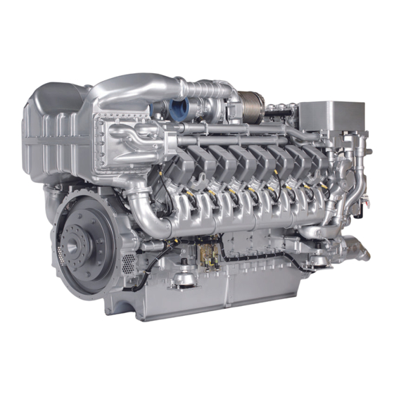
Page 19: Engine Layout
2.2 Engine layout 16 V 4000 R43 L/R 1 Oil heat exchanger 8 Intercooler 15 Generator 2 Crankcase breather 9 Starting equipment 16 Vibration damper (free 3 Power Output Module 10 Engine mount end) (POM) 11 Oil filler neck 17 Auxiliary PTO (battery- 4 Centrifugal oil filter 12 Cylinder head charging generator) - Page 20 1 Oil heat exchanger 8 Engine mount 15 Vibration damper (free 2 Crankcase breather 9 Additional fuel filter end) 3 Air intake 10 Oil filler neck 16 Auxiliary PTO 4 Exhaust turbocharger 11 Cylinder head 17 Coolant pump (HT) 5 Exhaust system 12 Fuel filter 18 Coolant pump (LT) 6 Intercooler...
-
Page 21: Sensors, Actuators And Injectors - Overview
2.3 Sensors, actuators and injectors – Overview Sensors, actuators 1 Engine governor 6 Sensor B34 (fuel pressure 11 Sensor B1 (camshaft 2 Sensor B3 (intake air tem- after filter) speed) perature) 7 Sensor F46 (leak-off fuel) 12 Sensor B48 (fuel pressure 3 Sensor B6 (coolant tem- 8 Sensor B5.1 (engine oil after HP pump) - Page 22 1 Sensor B50 (crankcase 4 Sensor B26 (charge-air 7 Sensor B10 (engine speed) pressure) coolant temperature) 2 Sensor B4.22 (exhaust 5 Sensor B13 (charge-air temperature B side) pressure) 3 Sensor B44.2 (turbocharg- 6 Sensor B9 (charge-air tem- er B speed) perature) 22 | General Information | MS15042/00E 2014-10...
- Page 23 Injectors A1 Injector Y39.1 A7 Injector Y39.7 B5 Injector Y39.15 A2 Injector Y39.2 A8 Injector Y39.8 B6 Injector Y39.16 A3 Injector Y39.3 B1 Injector Y39.11 B7 Injector Y39.17 A4 Injector Y39.4 B2 Injector Y39.12 B8 Injector Y39.18 A5 Injector Y39.5 B3 Injector Y39.13 A6 Injector Y39.6 B4 Injector Y39.14...
-
Page 24: Technical Data
3 Technical Data 3.1 16V 4000 R43 engine data Explanation: DL Ref. value: Continuous power BL Ref. value: Fuel stop power A Design value G Guaranteed value R Guideline value L Limit value, up to which the engine can be operated, without change (e.g. of power setting) N Not yet defined value - Not applicable X Applicable... - Page 25 Model-related data (basic design) Number of cylinders Number of cylinders Cylinder arrangement: V angle Degrees (°) Bore Stroke Cylinder displacement Liters 4.77 Total displacement Liters 76.3 Number of inlet valves per cylinder Number of exhaust valves per cylinder Combustion air / exhaust gas Number of cylinders Charge-air pressure before cylinder bar abs...
- Page 26 Number of cylinders Lube oil operating pressure before engine (measurement block) Lube oil operating pressure before engine, warning Lube oil operating pressure before engine, shutdown Lube oil operating pressure (low idle) (meas. point: before engine) Fuel system Number of cylinders Fuel pressure at engine inlet connection, min.
- Page 27 Acoustics Number of cylinders Exhaust noise, unsilenced - BL (free-field sound pressure level Lp, 1m dis- dB(A) tance, ISO 6798, +3dB(A) tolerance) Engine surface noise without intake noise - BL (free-field sound pressure level dB(A) Lp, 1m distance, ISO 6798, +2dB(A) tolerance) MS15042/00E 2014-10 | Technical Data | 27...
-
Page 28: 4000 R43L Engine Data
3.2 16 V 4000 R43L engine data Explanation: DL Reference value: Continuous power BL Reference value: Fuel stop power A Design value G Guaranteed value R Guideline value L Limit value up to which the engine can be operated without change (e.g. of power setting) N Undefined value - Not applicable X Applicable... - Page 29 Number of cylinders Stroke Cylinder displacement Liters 4.77 Total displacement Liters 76.3 Inlet valves per cylinder Exhaust valves per cylinder Air/exhaust gas Number of cylinders Charge-air pressure before cylinder bar abs Exhaust temperature after exhaust turbocharger °C – Coolant system (high-temperature circuit) Number of cylinders Coolant temperature (at engine connection: outlet to cooling system) °C...
- Page 30 Fuel system Number of cylinders Fuel pressure at engine inlet connection, min. (during engine start) -0.1 Fuel pressure at engine inlet connection, min. (during engine operation) -0.3 Fuel pressure at engine inlet connection, max. (during engine start) General operating data Number of cylinders Coolant preheating: Preheating temperature (min.) °C...
-
Page 31: 4000 R43R Engine Data
3.3 16 V 4000 R43R engine data Explanation: DL Ref. value: Continuous power BL Ref. value: Fuel stop power A Design value G Guaranteed value R Guideline value L Limit value, up to which the engine can be operated, without change (e.g. of power setting) N Not yet defined value - Not applicable X Applicable... - Page 32 Number of cylinders Stroke Cylinder displacement Liters 4.77 Total displacement Liters 76.3 Number of inlet valves per cylinder Number of exhaust valves per cylinder COMBUSTION AIR / EXHAUST GAS Number of cylinders Charge-air pressure before cylinder bar abs Exhaust temperature after turbocharger °C COOLANT SYSTEM (HT circuit) Number of cylinders...
- Page 33 FUEL SYSTEM Number of cylinders Fuel pressure at engine inlet connection, min. (when engine is starting) -0.3 Fuel pressure at engine inlet connection, min. (when engine is running) -0.3 Fuel pressure at engine inlet connection, max. (when engine is starting) GENERAL OPERATING DATA Number of cylinders Coolant preheating: preheating temperature (min.)
-
Page 34: Firing Order
3.4 Firing order Firing order Number of cylinders Firing order A1-B4-A4-A2-B3-A3-B2-B1 A1-B5-A5-B3-A3-B6-A6-B2-A2-B4-A4-B1 16 V A1-A7-B4-B6-A4-B8-A2-A8-B3-B5-A3-A5-B2-A6-B1-B7 20 V A1-B5-A8-B7-A5-B2-A7-B10-A2-B3-A10-B6-A3-B4-A6-B9-A4-B1-A9-B8 34 | Technical Data | MS15042/00E 2014-10... -
Page 35: Main Engine Dimensions
3.5 Main engine dimensions Main engine dimensions Item Dimension Length (A) 8 V approx. 2129 mm Length (A) 12 V approx. 2497 mm Length (A) 16 V approx. 3192 mm Length (A) 20 V approx. 3591 mm Width (B) 8 V approx. -
Page 36: Operation
4.1 Putting the engine into operation after extended out-of-service periods (>3 months) Preconditions ☑Engine is stopped and starting disabled. ☑MTU Preservation and Represervation Specifications (A001070/..) are available. Putting the engine into operation after extended out-of-service periods (>3 months) Item Action Engine Depreservation (→... -
Page 37: Putting The Engine Into Operation After Scheduled Out-Of-Service-Period
4.2 Putting the engine into operation after scheduled out-of- service-period Preconditions ☑Engine is stopped and starting disabled. Startup Item Action Lube oil system Check engine oil level (→ Page 117). Coolant circuit Check engine coolant level (→ Page 126); Check charge-air coolant level (→ Page 138). Coolant circuit Heat coolant with coolant preheater (if available;... -
Page 38: Starting The Engine In Manual Mode
4.3 Starting the engine in manual mode Preconditions ☑Engine is not under load. ☑External start interlock is not activated. DANGER Rotating and moving engine parts. Risk of crushing, danger of parts of the body being caught or pulled in! • Before cranking the engine with starter system, make sure that there are no persons in the en- gine's danger zone. -
Page 39: Stopping The Engine In Manual Mode
4.4 Stopping the engine in manual mode Preconditions ☑Engine not under load. ☑Engine in manual mode. NOTICE Stopping the engine when it is running at full load subjects it to extreme thermal and mechanical stresses. Overheating of and, therefore, damage to components is possible! •... -
Page 40: Preparing The Engine For Extended Out-Of-Service Period
Engine control system Switch off. Air intake and exhaust sys- Out-of-service-period > 1 week: • Seal engine's air and exhaust sides. Out-of-service-period > 1 month: • Preserve engine (→ MTU Preservation and Represervation Specifica- tions A001070/..). 40 | Operation | MS15042/00E 2014-10... -
Page 41: Plant - Cleaning
4.6 Plant – Cleaning Preconditions ☑Engine is stopped and starting disabled. ☑Operating voltage is not applied. Special tools, Material, Spare parts Designation / Use Part No. Qty. Steam jet cleaner Cleaner (Hakupur 312) 30390 WARNING Compressed air gun ejects a jet of pressurized air. Risk of injury to eyes and damage to hearing, risk of rupturing internal organs! •... -
Page 42: Maintenance
5 Maintenance 5.1 Maintenance task reference table [QL1] The maintenance tasks and intervals for this product are defined in the Maintenance Schedule. The Maintenance Schedule is a stand-alone publication. The task numbers in this table provide reference to the maintenance tasks specified in the Maintenance Schedule. - Page 43 Task Maintenance tasks W1577 Check turbine housing externally for cracks, perform endoscop- (→ Page 104) ic examination to check it internally for cracks, replace if neces- sary. W1713 Injector: Reset drift compensation parameters (CDC). (→ Page 150) Table 2: Maintenance task reference table [QL1] MS15042/00E 2014-10 | Maintenance | 43...
-
Page 44: Troubleshooting
6 Troubleshooting 6.1 Troubleshooting Engine does not turn when starter is actuated Component Probable Cause Measure Battery Low or faulty Charge or replace (see manufacturer's documentation). Cable connections faulty Check if cable connections are properly secured (see manufacturer's documen- tation). Starter Engine cabling or starter faulty Check if cable connections are properly... - Page 45 Contact Service. Charge air temperature too high Component Probable Cause Measure Engine coolant Engine coolant treatment incorrect Check (MTU test kit). Intercooler Contaminated Contact Service. Engine room Air-intake temperature too high Check fans and intake/exhaust lines. Charge-air pressure too low...
- Page 46 White exhaust gas Component Probable Cause Measure Engine Not at operating temperature Run engine to reach operating tempera- ture. Fuel system Water in fuel Check fuel system at fuel prefilter Drain fuel prefilter Intercooler Leaking Contact Service. 46 | Troubleshooting | MS15042/00E 2014-10...
-
Page 47: Fault Messages On Pau Display
6.2 Fault messages on PAU display The fault code numbers are generated by the engine governor and, depending on the relevant control system, transmitted to the display. The display is a two-line B/W-LCD for 16 ASCII characters per line and equipped with background illu- mination. -
Page 48: Fault Messages Of Engine Governor Adec (Ecu 7) For Series 4000, Rail Applications
6.3 Fault messages of engine governor ADEC (ECU 7) for Series 4000, rail applications 3 – HI T-Fuel Yellow alarm; warning Cause Corrective action u Reduce power. Fuel temperature too high. 4 – SS T-Fuel L2 Red alarm; power reduction ≥ 20%; forced idle Cause Corrective action Fuel temperature too high. - Page 49 15 – LO P-Lube Oil Yellow alarm; warning Cause Corrective action u Check oil level, top up as necessary (→ Page 117). Lube oil pressure too low. 16 – SS P-Lube Oil L2 Red alarm; engine stop Cause Corrective action Lube oil pressure too low.
- Page 50 25 – HI P-Diff. Lube Oil Yellow alarm; warning Cause Corrective action u Replace oil filter (→ Page 121). Differential pressure at oil filter too high. 26 – HI P-Diff. Lube Oil Red alarm; power reduction ≥ 20% Cause Corrective action Differential pressure at oil filter 1.
- Page 51 37 – SS ETC2 Overspeed L2 Red alarm; power reduction ≥ 20% Cause Corrective action ETC2 (B-side) speed too high. 1. Reduce power. 2. Check air filter. 3. Request towing locomotive if required. 51 – HI T-Lube Oil Yellow alarm; warning Cause Corrective action Lube oil temperature too high.
- Page 52 63 – HI P-Crankcase Yellow alarm; warning Cause Corrective action Crankcase pressure too high. 1. Reduce power. 2. Replace oil separator element. 64 – SS P-Crankcase L2 Red alarm; engine stop Cause Corrective action Crankcase pressure too high. 1. Request towing locomotive if required. 2.
- Page 53 81 – AL Rail Leakage Yellow alarm; warning Cause Corrective action u Contact Service. Pressure gradient in rail is too low during starting or too high during stopping; HP system leaky; air in system. 82 – HI P-Fuel (Common Rail) L1 Red alarm;...
- Page 54 91 – SS No Runup Speed Yellow alarm; warning Cause Corrective action Runup speed not reached. 1. Check battery. 2. Check starter. 3. Initiate new starting attempt. 4. Request towing locomotive if required. 92 – SS No Starter Speed Yellow alarm; warning Cause Corrective action Starter speed not reached;...
- Page 55 104 – AL Operating Hrs. Meter Defective Yellow alarm; warning Cause Corrective action u Contact Service. Hour meter faulty. 118 – LO ECU Supply Voltage Yellow alarm; warning Cause Corrective action Supply voltage too low. u Check ECU supply voltage. 119 –...
- Page 56 177 – AL LifeData Restore Incomplete Yellow alarm; warning Cause Corrective action u Contact Service. This fault message is generated if a CRC is faulty during a data upload (to the engine governor) (indicated for each indiv. module). 180 – AL CAN1 Node Lost Yellow alarm;...
- Page 57 184 – AL CAN PU-Data Flash Error Yellow alarm; warning Cause Corrective action u Contact service for electronic equipment. A programming error occurred when attempting to copy a received PU data module into the Flash module. 186 – AL CAN1 Bus Off Yellow alarm;...
- Page 58 202 – SD T-Fuel Red alarm; power reduction ≥ 20% Cause Corrective action u Check sensor B33 and wiring, replace as necessary Fuel temperature sensor faulty; short circuit or wire break. (→ Page 149). 203 – SD T-Charge Air Yellow alarm; power limitation < 20%; Cause Corrective action Charge-air temperature sensor...
- Page 59 208 – SD P-Charge Air Yellow alarm; power limitation < 20%; Cause Corrective action u Check sensor B10 and wiring, replace as necessary Charge-air pressure sensor faulty; short circuit or wire (→ Page 149). break. 211 – SD P-Lube Oil Yellow alarm;...
- Page 60 222 – SD Leak Fuel Level Yellow alarm; warning Cause Corrective action u Check sensor F46 and wiring, replace as necessary Leak fuel level sensor faulty; short circuit or wire break. (→ Page 149). 227 – SD P-Oil bef. Filter Yellow alarm;...
- Page 61 233 – SD ETC Speed 2 Yellow alarm; warning Cause Corrective action u Check sensor B44.2 and wiring, replace as necessary Speed sensor of primary turbocharger faulty; short circuit (→ Page 149). or wire break. 240 – SD P-Fuel Yellow alarm; warning Cause Corrective action u Check sensor B34 and wiring, replace as necessary...
- Page 62 322 – AL Wiring Cylinder A2 Yellow alarm; warning Cause Corrective action u Check solenoid valve. Short circuit in cylinder injector wiring. Result: Misfiring. 323 – AL Wiring Cylinder A3 Yellow alarm; warning Cause Corrective action Short circuit in cylinder injector u Check solenoid valve.
- Page 63 329 – AL Wiring Cylinder A9 Yellow alarm; warning Cause Corrective action u Check solenoid valve. Short circuit in cylinder injector wiring. Result: Misfiring. 330 – AL Wiring Cylinder A10 Yellow alarm; warning Cause Corrective action Short circuit in cylinder injector u Check solenoid valve.
- Page 64 336 – AL Wiring Cylinder B6 Yellow alarm; warning Cause Corrective action u Check solenoid valve. Short circuit in cylinder injector wiring. Result: Misfiring. 337 – AL Wiring Cylinder B7 Yellow alarm; warning Cause Corrective action Short circuit in cylinder injector u Check solenoid valve.
- Page 65 343 – AL Open Load Cylinder A3 Yellow alarm; warning Cause Corrective action u Check solenoid valve. Open circuit in cylinder injector wiring. Result: Misfiring. 344 – AL Open Load Cylinder A4 Yellow alarm; warning Cause Corrective action Open circuit in cylinder injector u Check solenoid valve.
- Page 66 350 – AL Open Load Cylinder A10 Yellow alarm; warning Cause Corrective action u Check solenoid valve. Open circuit in cylinder injector wiring. Result: Misfiring. 351 – AL Open Load Cylinder B1 Yellow alarm; warning Cause Corrective action Open circuit in cylinder injector u Check solenoid valve.
- Page 67 357 – AL Open Load Cylinder B7 Yellow alarm; warning Cause Corrective action u Check solenoid valve. Open circuit in cylinder injector wiring. Result: Misfiring. 358 – AL Open Load Cylinder B8 Yellow alarm; warning Cause Corrective action Open circuit in cylinder injector u Check solenoid valve.
- Page 68 363 – AL Stop Power Stage Red alarm; engine stop Cause Corrective action Internal electronic fault, 1. Check wiring (→ Page 149). electronics possibly faulty. 2. Acknowledge alarm. 3. Restart engine . 4. Request towing locomotive if required. 365 – AL Stop SV-Wiring Ground Red alarm;...
- Page 69 408 – AL Open Load Emerg. Stop Input ESI Yellow alarm; warning Cause Corrective action Line disruption on the input for 1. Check wiring (→ Page 149). emergency stop; wiring 2. Check target device input. defective or no resistance through the switch. 410 –...
- Page 70 454 – SS Power Reduction Active CAN message Cause Corrective action Alarm is only available as a 1. Observe any other messages. separate CAN message, power 2. Determine and rectify cause of power reduction. reduction is active. 470 – SD T-ECU Yellow alarm;...
- Page 71 479 – AL Comb. Alarm Red (Plant) Red alarm Cause Corrective action u Observe any other messages. Combined alarm initiated by plant. 500 – AL Wiring POM Starter 1 Yellow alarm; warning Cause Corrective action A wiring fault in connection of u Check connection between POM and starter.
- Page 72 506 – AL Starter Voltage too low Yellow alarm; warning Cause Corrective action u Check starter battery and wiring (→ Page 149). The battery voltage is too low for the starting process. 507 – AL POM Error Yellow alarm; warning Cause Corrective action A general POM fault occurred.
- Page 73 551 – SS Engine Overspeed Camshaft Red alarm; engine stop Cause Corrective action Camshaft overspeed. 1. Request towing locomotive. 2. Contact Service. 577 – SD T-Lube Oil in Oil Pan (Option) Yellow alarm; warning Cause Corrective action Oil pan temperature sensor u Check sensor B7.2 and wiring, replace as necessary faulty;...
- Page 74 596 – AL Develop PR Set Yellow alarm; warning Cause Corrective action u Contact Service. Standard production data record available. The data record stored is for testing. 600 – SD T-Exhaust A+B Red alarm; power reduction ≥ 20% Cause Corrective action u Check sensor and wiring (B4.21 and B.22), replace as Exhaust temperature sensor on A and B sides defective;...
-
Page 75: Task Description
7 Task Description 7.1 Engine 7.1.1 Engine – Barring manually Preconditions ☑Engine is stopped and starting disabled. Special tools, Material, Spare parts Designation / Use Part No. Qty. Barring device F6555766 Ratchet with extension F30006212 DANGER Rotating and moving engine parts. Risk of crushing, danger of parts of the body being caught or pulled in! •... - Page 76 Engage barring device (2) in ring gear of fly- wheel and install it on flywheel housing. Fit ratchet (1) onto barring device (2). Note: No resistance other than compression re- sistance must be encountered. Rotate crankshaft in engine direction of ro- tation.
-
Page 77: Cranking Engine With Starting System
7.1.2 Cranking engine with starting system DANGER Rotating and moving engine parts. Risk of crushing, danger of parts of the body being caught or pulled in! • Before cranking the engine with starter system, make sure that there are no persons in the en- gine's danger zone. -
Page 78: Engine - Performing Test Run
7.1.3 Engine – Performing test run DANGER Rotating and moving engine parts. Risk of crushing, danger of parts of the body being caught or pulled in! • Before cranking the engine with starter system, make sure that there are no persons in the en- gine's danger zone. -
Page 79: Cylinder Liner
7.2 Cylinder Liner 7.2.1 Cylinder liner – Endoscopic examination Preconditions ☑Engine is stopped and starting disabled Special tools, Material, Spare parts Designation / Use Part No. Qty. Barring device F6555766 Ratchet with extension F30006212 Endoscope Y20097353 Preparatory steps Remove cylinder head cover (→ Page 90). Remove injector (→... - Page 80 Compile endoscopic report using the table. Use technical terms to describe the liner surface (→ Page 81). Depending on findings: • Do not take any action or • carry out a further endoscopic examination as part of maintenance work or •...
-
Page 81: Instructions And Comments On Endoscopic And Visual Examination Of Cylinder Liners
7.2.2 Instructions and comments on endoscopic and visual examination of cylinder liners Terms used for endoscopic examination Use the terms listed below to describe the condition of the cylinder-liner surface in the endoscopic ex- amination report. Findings Explanations/Action Minor dirt scores Minor dirt scores can occur during the assembly of a new engine (honing products, particles, broken-off burrs). - Page 82 Evaluation of findings and further measures The findings in the start phase of oxidation discoloration and heat discoloration are similar. A thorough investigation and compliance with the above evaluation criteria allow an unambiguous evaluation. To avoid unnecessary disassembly work, it is recommended that another inspection be carried out after further operation of the engine.
-
Page 83: Crankcase Breather
7.3 Crankcase Breather 7.3.1 Crankcase breather – Oil separator element replacement Preconditions ☑Engine is stopped and starting disabled. Special tools, Material, Spare parts Designation / Use Part No. Qty. Torque wrench, 4-20 Nm F30044239 Ratchet adapter F30027340 Engine oil Filter element (→... - Page 84 Use torque wrench to tighten the screws (2) of cover (1) to the specified torque. Name Size Type Lubricant Value/Standard Screw Tightening torque (Engine oil) 10 Nm −2 Nm Replace further oil filter elements in the same way. Check oil separator for leaks. 84 | Task Description | MS15042/00E 2014-10...
-
Page 85: Valve Drive
7.4 Valve Drive 7.4.1 Valve gear – Lubrication Preconditions ☑Engine is stopped and starting disabled. Special tools, Material, Spare parts Designation / Use Part No. Qty. Engine oil Valve gear – Lubrication Remove cylinder head covers (→ Page 90). Fill oil chambers of valve bridges with oil. Fill oil chambers of rocker arms and adjust- ing screws with oil. -
Page 86: Valve Clearance - Check And Adjustment
7.4.2 Valve clearance – Check and adjustment Preconditions ☑Engine is stopped and starting disabled. ☑Engine coolant temperature is max. 40 °C. ☑Valves are closed. Special tools, Material, Spare parts Designation / Use Part No. Qty. Feeler gauge Y20098771 Torque wrench, 60-320 Nm F30452768 Socket wrench, 24 mm F30039526... - Page 87 Diagram for 8V engines – Two crankshaft positions Diagram for 12V engines – Two crankshaft positions Diagram for 16V engines – Two crankshaft positions MS15042/00E 2014-10 | Task Description | 87...
-
Page 88: Adjusting Valve Clearance
Diagram for 20V engines – Two crankshaft positions Checking valve clearance at two crankshaft positions Check TDC position of piston in cylinder A1: • If the rocker arms are unloaded on cylinder A1, the piston is in firing TDC. • If the rocker arms are under load on cylinder A1, the piston is in overlap TDC. Check valve clearance with cold engine: •... - Page 89 Tighten locknut (1) with torque wrench to the specified tightening torque, holding the adjusting screw (2) to prevent it from turning. Name Size Type Lubricant Value/Standard Locknut M16 x 1.5 Tightening torque (Engine oil) 90 Nm +9 Nm Replace or rectify adjusting screws and/or locknuts which do not move freely. Check valve clearance.
-
Page 90: Cylinder Head Cover - Removal And Installation
7.4.3 Cylinder head cover – Removal and installation Preconditions ☑Engine is stopped and starting disabled. Special tools, Material, Spare parts Designation / Use Part No. Qty. Assembly compound (Kluthe Hakuform 30-15) X00067260 O-ring (→ Spare Parts Catalog) Removing cylinder head cover Clean very dirty cylinder head covers (1) prior to removal. -
Page 91: Injection Pump / Hp Pump
7.5 Injection Pump / HP Pump 7.5.1 HP pump – Relief bore check DANGER Rotating and moving engine parts. Risk of crushing, danger of parts of the body being caught or pulled in! • Only run the engine at low power. Keep away from the engine's danger zone. WARNING High level of engine noise when the engine is running. -
Page 92: Hp Pump - Filling With Engine Oil
7.5.2 HP pump – Filling with engine oil Preconditions ☑Engine is stopped and starting disabled. Special tools, Material, Spare parts Designation / Use Part No. Qty. Engine oil WARNING Fuels are combustible. Risk of fire and explosion! • Avoid open flames, electrical sparks and ignition sources. •... -
Page 93: Injection Valve / Injector
7.6 Injection Valve / Injector 7.6.1 Injector – Replacement Special tools, Material, Spare parts Designation / Use Part No. Qty. Injector (→ Spare Parts Catalog) Injector – Replacement Remove injector and install new one (→ Page 94). MS15042/00E 2014-10 | Task Description | 93... -
Page 94: Injector - Removal And Installation
7.6.2 Injector – Removal and installation Preconditions ☑Engine is stopped and starting disabled. Special tools, Material, Spare parts Designation / Use Part No. Qty. Installation/removal tool F6789889 Milling cutter F30452739 Torque wrench, 0.5-5 Nm 0015384230 Torque wrench, 10-60 Nm F30452769 Ratchet adapter F30027340 Torque wrench, 60-320 Nm... - Page 95 Remove HP fuel line (4). Note: While the adapter is removed, the injector is drained. Remove adapter (3). Remove screw (2) and take off hold-down clamp (1). Install installation/removal tool on cylinder head. Remove injector with installation/removal tool. Remove installation/removal tool. Remove sealing ring (4) from injector or use a self-made hook to take it out of the cylinder head.
- Page 96 Installing injector Remove plug before installing the injec- tor. (Do not remove the plug from the HP line before installing the adapter). Coat injector with assembly paste at the seat of the nozzle retaining nut. Fit new sealing ring (included in the scope of delivery of the injector) with assembly compound on injector, observe installation position of sealing ring.
- Page 97 Coat bolt mating face (2) and thread with engine oil. Fit hold-down clamp (1) in the correct position and use torque wrench to tighten screw (2) to the speci- fied initial tightening torque. Name Size Type Lubricant Value/Standard Screw Preload torque (Engine oil) 5 Nm to 10 Nm Note:...
- Page 98 Loosen double-walled HP line (5) and follow the same sequence to tighten to the specified torque. Tightening sequence: 1 Adapter (4) 2 Rail (6) Name Size Type Lubricant Value/Standard Union nut / thrust Tightening torque (Engine oil) 40 Nm + 5 Nm screw Fit connectors on injector.
-
Page 99: Fuel System
7.7 Fuel System 7.7.1 Fuel system – Venting Preconditions ☑Engine is stopped and starting disabled. Special tools, Material, Spare parts Designation / Use Part No. Qty. Fuel WARNING Fuels are combustible. Risk of fire and explosion! • Avoid open flames, electrical sparks and ignition sources. •... -
Page 100: Fuel Filter
7.8 Fuel Filter 7.8.1 Fuel filter – Replacement Preconditions ☑Engine is stopped and starting disabled. Special tools, Material, Spare parts Designation / Use Part No. Qty. Filter wrench F30379104 Engine oil Easy-change filter (→ Spare Parts Catalog) WARNING Fuels are combustible. Risk of fire and explosion! •... -
Page 101: Fuel Prefilter - Draining
7.8.2 Fuel prefilter – Draining Preconditions ☑Engine is stopped and starting disabled. Special tools, Material, Spare parts Designation / Use Part No. Qty. Diesel fuel Sealing (→ Spare Parts Catalog) WARNING Fuels are combustible. Risk of fire and explosion! • Avoid open flames, electrical sparks and ignition sources. •... -
Page 102: Fuel Prefilter - Filter Element Replacement
7.8.3 Fuel prefilter – Filter element replacement Preconditions ☑Engine is stopped and starting disabled. Special tools, Material, Spare parts Designation / Use Part No. Qty. Diesel fuel Filter element (→ Spare Parts Catalog) Gasket (→ Spare Parts Catalog) WARNING Fuels are combustible. Risk of fire and explosion! •... -
Page 103: Intermediate Fuel Filter - Replacement
7.8.4 Intermediate fuel filter – Replacement Preconditions ☑Engine is stopped and starting disabled. Special tools, Material, Spare parts Designation / Use Part No. Qty. Filter wrench F30379104 Engine oil Easy-change filter (→ Spare Parts Catalog) WARNING Fuels are combustible. Risk of fire and explosion! •... -
Page 104: Exhaust Turbocharger
7.9.1 Exhaust turbocharger – Turbine housing check Special tools, Material, Spare parts Designation / Use Part No. Qty. Endoscope Y20097353 Engine oil Assembly compound (Ultra-Therm MTU) 50547 2-component adhesive 50712 Turbine housing (→ Spare Parts Catalog) Seal (→ Spare Parts Catalog) - Page 105 Clamp (1) Tightening torque (Assembly compound 24 Nm +3 Nm (Ultra-Therm MTU)) Note: Secure bellows on engine side first, then on locomotive side. Coat screw threads and clamping area of clamps (3,6) with assembly compound prior to installation. Align bellows (4) and clamps (3,6) according to the markings or the photos.
- Page 106 Lubricant Value/Standard Clamp (6) Tightening torque (Assembly compound 20 Nm (Ultra-Therm MTU)) Installing containment cover Fit new seal in bellows (12), glue with 2- component adhesive. Coat screw threads and clamping area of clamp (11) with assembly compound prior to installation.
-
Page 107: Compressor Wheel - Cleaning
7.9.2 Compressor wheel – Cleaning Preconditions ☑Engine is stopped and starting disabled. Special tools, Material, Spare parts Designation / Use Part No. Qty. Torque wrench, 10-60 Nm F30452769 Ratchet adapter F30027340 Cleaner 40377 Engine oil Sealing rings 700429160001 Sealing rings 700429300000 Gasket X52499100020... - Page 108 Remove screws (1) from charge-air pipe to compressor housing. Loosen clamps on air intake (1). Remove air intake. Loosen clamp (2). Remove intake housing (1). 108 | Task Description | MS15042/00E 2014-10...
- Page 109 Loosen clamp (2). Remove compressor housing (1). Compressor wheel – Cleaning Note: Do not use wire brush, scraper or similar tools for cleaning. Clean compressor housing with a smooth paint brush or brush. Clean compressor wheel (1) and bearing housing (2). Thoroughly remove cleaner from all compo- nents.
- Page 110 Position clamp (2) and tighten to specified torque using a torque wrench. Name Size Type Lubricant Value/Standard Clamp Tightening torque max. 27 Nm Install intake housing (1) with new sealing ring. Position clamp (2) and tighten to specified torque using a torque wrench. Name Size Type...
-
Page 111: Charge-Air Cooling
7.10 Charge-Air Cooling 7.10.1 Intercooler – Checking condensate drain for coolant leakage and obstruction DANGER Rotating and moving engine parts. Risk of crushing, danger of parts of the body being caught or pulled in! • Only run the engine at low power. Keep away from the engine's danger zone. WARNING High level of engine noise when the engine is running. -
Page 112: Air Filter
7.11 Air Filter 7.11.1 Air filter element and (optional) dust bowl ‒ Cleaning Preconditions ☑Engine is stopped and starting disabled. Special tools, Material, Spare parts Designation / Use Part No. Qty. Sealing (→ Spare Parts Catalog) WARNING Compressed air gun ejects a jet of pressurized air. Risk of injury to eyes and damage to hearing, risk of rupturing internal organs! •... -
Page 113: Air Filter - Replacement
7.11.2 Air filter ‒ Replacement Special tools, Material, Spare parts Designation / Use Part No. Qty. Air filter (→ Spare Parts Catalog) Air filter ‒ Replacement Remove air filter and install new one (→ Page 114). Reset signal ring of service indicator (→ Page 116). MS15042/00E 2014-10 | Task Description | 113... -
Page 114: Air Filter Element - Removal And Installation
7.11.3 Air filter element – Removal and installation (optional) Preconditions ☑Engine is stopped and starting disabled. Special tools, Material, Spare parts Designation / Use Part No. Qty. Sealing (→ Spare Parts Catalog) Air filter element – Removal and installation Release latches (9). Remove dust bowl (8) and partition (7). -
Page 115: Starting Equipment
7.12 Starting Equipment 7.12.1 Starter – Condition check Preconditions ☑Engine is stopped and starting disabled. Checking starter condition Check securing screws of starter for secure seating and tighten if required. Check wiring (→ Page 149). MS15042/00E 2014-10 | Task Description | 115... -
Page 116: Air Intake
7.13 Air Intake 7.13.1 Service indicator – Signal ring position check Preconditions ☑Engine is stopped and starting disabled. Checking signal ring position If the signal ring is completely visible in the control window (2), replace air filter (→ Page 113). After installation of new filter, press reset button (1). -
Page 117: Lube Oil System, Lube Oil Circuit
7.14 Lube Oil System, Lube Oil Circuit 7.14.1 Engine oil – Level check Preconditions ☑Engine is stopped and starting disabled. Oil level check prior to engine start Withdraw dipstick from guide tube and wipe it. Insert dipstick into guide tube to stop, withdraw after approx. -
Page 118: Engine Oil – Change
7.14.2 Engine oil – Change Preconditions ☑Engine is stopped and starting disabled. ☑Engine is at operating temperature. ☑MTU Fluids and Lubricants Specifications (A001061/..) are available. Special tools, Material, Spare parts Designation / Use Part No. Qty. Torque wrench, 60-320 Nm... - Page 119 Draining residual oil from equip- ment carrier (only with unsched- uled engine oil change) Provide a suitable container in which to col- lect the engine oil. Remove drain plug (1) and drain engine oil from engine oil heat exchanger and from engine oil filter.
-
Page 120: Engine Oil – Sample Extraction And Analysis
7.14.3 Engine oil – Sample extraction and analysis Preconditions ☑MTU Fluids and Lubricants Specifications (A001061/..) are available. Special tools, Material, Spare parts Designation / Use Part No. Qty. MTU test kit 5605892099/00 DANGER Rotating and moving engine parts. Risk of crushing, danger of parts of the body being caught or pulled in! •... -
Page 121: Oil Filtration / Cooling
7.15 Oil Filtration / Cooling 7.15.1 Engine oil filter – Replacement Preconditions ☑Engine is stopped and starting disabled. Special tools, Material, Spare parts Designation / Use Part No. Qty. Filter wrench F30379104 Engine oil Oil filter (→ Spare Parts Catalog) WARNING Hot oil. -
Page 122: Checking Oil Indicator Filter
7.15.2 Checking oil indicator filter Preconditions ☑Engine is stopped and starting disabled. Special tools, Material, Spare parts Designation / Use Part No. Qty. Cleaner (Snow-White 11-0) 40460 Cleaner (Hakupur 312) 30390 Engine oil Strainer (→ Spare Parts Catalog) Square-section ring (→... - Page 123 Cleaning strainer Shake coarse contamination out of strainer (5). Clean all metallic parts with cleaner (Snow-White 11-0), then rinse with cleaner (Hakupur 312). Note: Do not damage the fabric of the strainer. Use a soft brush to remove stubborn deposits from strainer if required. Blow out strainer (5) with compressed air from inside.
-
Page 124: Centrifugal Oil Filter – Cleaning And Filter Sleeve Replacement
7.15.3 Centrifugal oil filter – Cleaning and filter-sleeve replacement Preconditions ☑Engine is stopped and starting disabled. Special tools, Material, Spare parts Designation / Use Part No. Qty. Torque wrench, 4-20 Nm F30044239 Torque wrench, 10-60 Nm F30452769 Cold cleaner (Hakutex 60) X00056750 Filter sleeve (→... - Page 125 Centrifugal oil filter – Cleaning and filter-sleeve replacement Remove clamp (14). Release Tommy nut (2) and take off cov- er (1). Carefully lift rotor (11), allow oil to drain and remove from housing. Holding the rotor (11) firmly, release rotor cover nut (3).
-
Page 126: Circuit
7.16 Coolant Circuit, General, High-Temperature Circuit 7.16.1 Engine coolant – Level check Preconditions ☑Engine is stopped and starting disabled. ☑MTU Fluids and Lubricants Specifications (A001061/..) are available. WARNING Coolant is hot and under pressure. Risk of injury and scalding! • Let the engine cool down. -
Page 127: Engine Coolant – Change
7.16.2 Engine coolant – Change Special tools, Material, Spare parts Designation / Use Part No. Qty. Coolant Engine coolant change Drain engine coolant (→ Page 128). Fill with engine coolant (→ Page 129). MS15042/00E 2014-10 | Task Description | 127... -
Page 128: Engine Coolant – Draining
7.16.3 Engine coolant – Draining Preconditions ☑Engine is stopped and starting disabled. WARNING Coolant is hot and under pressure. Risk of injury and scalding! • Let the engine cool down. • Wear protective clothing, gloves, and goggles / safety mask. Preparatory steps Provide a suitable receptacle to catch the coolant. -
Page 129: Replenishing Engine Coolant
7.16.4 Replenishing engine coolant Preconditions ☑Engine shut down and secured against being restarted. ☑MTU Fluids and Lubricants Specifications (A001061/..) are available. Special tools, Material, Spare parts Designation / Use Part No. Qty. Coolant WARNING Coolant is hot and under pressure. - Page 130 Replenishing coolant using a pump Connect a suitable pump with a hose to the drain valve (arrowed). Open bleed valve on distributor block (ar- rowed). Open drain valve and pump coolant into en- gine at 0.5 bar minimum. When coolant emerges from the bleed valve, close the bleed valve.
- Page 131 Alternatively: top up coolant through filler neck Open bleed valve on distributor block (ar- rowed). Add coolant to expansion tank until the coolant level at the overflow remains con- stant. When coolant emerges from the bleed valve, close the bleed valve. Check pressure cap is in perfect condition and clean sealing faces if necessary.
-
Page 132: Engine Coolant Pump – Relief Bore Check
7.16.5 Engine coolant pump – Relief bore check DANGER Rotating and moving engine parts. Risk of crushing, danger of parts of the body being caught or pulled in! • Only run the engine at low power. Keep away from the engine's danger zone. WARNING High level of engine noise when the engine is running. -
Page 133: Engine Coolant – Sample Extraction And Analysis
7.16.6 Engine coolant – Sample extraction and analysis Preconditions ☑MTU Fluids and Lubricants Specifications (A001061/..) are available. Special tools, Material, Spare parts Designation / Use Part No. Qty. MTU test kit 5605892099/00 DANGER Rotating and moving engine parts. Risk of crushing, danger of parts of the body being caught or pulled in! •... -
Page 134: Preheating Unit – Overview
7.16.7 Preheating unit – Overview Preheating unit 1 Preheating unit 134 | Task Description | MS15042/00E 2014-10... - Page 135 Coolant line holders 1 Preheating unit 3 Washer 5 Washer 2 Screw 4 Clamp 6 Nut MS15042/00E 2014-10 | Task Description | 135...
-
Page 136: Preheater Unit – Removal
7.16.8 Preheater unit – Removal DANGER Electric voltage supply for operation. Danger of burns and fatal electric shock! • Make certain that the power supply to the product is switched off before starting work. Secure against unintentional switching on! WARNING The component is very heavy and may fall or tip over if unstable. -
Page 137: Preheater Unit – Installation
7.16.9 Preheater unit – Installation Special tools, Material, Spare parts Designation / Use Part No. Qty. Sealing ring (→ Spare Parts Catalog) DANGER Electric voltage supply for operation. Danger of burns and fatal electric shock! • Make certain that the power supply to the product is switched off before starting work. Secure against unintentional switching on! WARNING The component is very heavy and may fall or tip over if unstable. -
Page 138: Low-Temperature Circuit
7.17 Low-Temperature Circuit 7.17.1 Charge-air coolant – Level check Preconditions ☑Engine is stopped and starting disabled. ☑MTU Fluids and Lubricants Specifications (A001061/..) are available. WARNING Coolant is hot and under pressure. Risk of injury and scalding! • Let the engine cool down. -
Page 139: Charge-Air Coolant – Change
7.17.2 Charge-air coolant – Change Special tools, Material, Spare parts Designation / Use Part No. Qty. Coolant Charge-air coolant – Change Drain charge-air coolant (→ Page 140). Fill with charge-air coolant (→ Page 141). MS15042/00E 2014-10 | Task Description | 139... -
Page 140: Charge-Air Coolant – Draining
7.17.3 Charge-air coolant – Draining Preconditions ☑Engine is stopped and starting disabled. Special tools, Material, Spare parts Designation / Use Part No. Qty. Sealing ring (→ Spare Parts Catalog) WARNING Coolant is hot and under pressure. Risk of injury and scalding! •... -
Page 141: Charge-Air Coolant – Filling
7.17.4 Charge-air coolant – Filling Preconditions ☑Engine is stopped and starting disabled. ☑MTU Fluids and Lubricants Specifications (A001061/..) are available. Special tools, Material, Spare parts Designation / Use Part No. Qty. Coolant WARNING Coolant is hot and under pressure. Risk of injury and scalding! •... - Page 142 Filling with coolant using a pump Connect a suitable pump with a hose to the drain valve (arrowed). Loosen the vent line union at the distribu- tor piece (arrowed). Open drain valve and pump coolant into en- gine at 0.5 bar minimum. Tighten the union (arrowed) if coolant leaks out at the loose union.
- Page 143 Alternatively: Filling with cool- ant through filler neck Loosen the vent line union at the distribu- tor piece (arrowed). Top up coolant in expansion tank via filler neck until coolant level at top edge of filler neck remains constant. Tighten the union (arrowed) if coolant leaks out at the loose union.
-
Page 144: Charge-Air Coolant Pump – Relief Bore Check
7.17.5 Charge-air coolant pump – Relief bore check DANGER Rotating and moving engine parts. Risk of crushing, danger of parts of the body being caught or pulled in! • Only run the engine at low power. Keep away from the engine's danger zone. WARNING High level of engine noise when the engine is running. -
Page 145: Engine Mounting / Support
7.18 Engine Mounting / Support 7.18.1 Engine mounts – Resilient element check Preconditions ☑Engine is stopped and starting disabled. ☑Engine filled with coolant and engine oil. Special tools, Material, Spare parts Designation / Use Part No. Qty. Feeler gauge Y20010128 Vernier caliper Y20001743 Combination box and open-end wrench... - Page 146 Engine mounts – Buffer clear- ance check Check dimension (A) with feeler gauge on measuring groove (arrow). If dimension (A) is not 4 mm ±0.3 mm, ad- just buffer clearance. Engine mounts – Buffer clear- ance adjustment Take off protective cap (1). Remove nut (3).
-
Page 147: Drive, Power Generation And Safety Systems
7.19 Drive, Power Generation and Safety Systems 7.19.1 Generator – Greasing antifriction bearing Preconditions ☑Engine is running. Special tools, Material, Spare parts Designation / Use Part No. Qty. Grease gun (→ Tools Catalog) ISOFLEX TOPAS NB 52, manufacturer: Klüber DANGER Rotating and moving engine parts. -
Page 148: Generator – Cleaning Intake Air Grille
7.19.2 Generator – Cleaning intake air grille Preconditions ☑Engine is stopped and starting disabled. Special tools, Material, Spare parts Designation / Use Part No. Qty. Vacuum cleaner (→ Tools Catalog) Cleaning intake air grille Clean intake air grille on generator dry. Use vacuum cleaner to remove dust from intake air grille. -
Page 149: Wiring (General) For Engine/Gearbox/Unit
7.20 Wiring (General) for Engine/Gearbox/Unit 7.20.1 Еngine cabling ‒ Check Preconditions ☑Engine is stopped and starting disabled. Special tools, Material, Spare parts Designation / Use Part No. Qty. Solvent (isopropyl alcohol) X00058037 Еngine cabling ‒ Check Check securing screws of cable clamps on engine and tighten loose threaded connections. Ensure that cables are fixed in their clamps and cannot swing freely. -
Page 150: Accessories For (Electronic) Engine Governor / Control System
7.21 Accessories for (Electronic) Engine Governor / Control System 7.21.1 CDC parameters – Reset with DiaSys® Preconditions ☑Engine is stopped and starting disabled. Resetting CDC parameters (DiaSys® is available) Note: The CDC parameters must be reset, otherwise the emission certification of the engine is no longer ap- plicable. -
Page 151: Engine Governor And Connectors – Cleaning
7.21.2 Engine governor and connectors – Cleaning Preconditions ☑Engine is stopped and starting disabled. Special tools, Material, Spare parts Designation / Use Part No. Qty. Solvent (isopropyl alcohol) X00058037 Note: Always use test connectors to enter the connectors. Never use test leads for this purpose. Otherwise the contacts could be bent. -
Page 152: Engine Governor Plug Connections – Check
7.21.3 Engine governor plug connections – Check Preconditions ☑Engine stopped and starting disabled. NOTICE Insertion of unsuitable test probe, e.g. test prod. The contacts in the plug connection can be bent! • Carry out check of plug connection only with test connectors. Checking plug connections at engine governor Check all plug connections for secure seating. -
Page 153: Abbreviations
Exhaust gas recirculation Alarm ANSI American National Standards Institute Backup Data Module Series Fluids and lubricants specification/preser- MTU publication no. A00.. vation specification Controller Area Network Data bus system, bus standard CaPoS Capacitor Power System Capacitor-based starting system Calibration Drift Compensation Drift compensation must be reset in the engine con- trol system using DiaSys®... - Page 154 Abbre- Meaning Explanation viation Initial injector equalization The injector code must be entered in the engine con- trol system using DiaSys® to ensure optimum emis- sions and consumption characteristics. International Organization for Standardiza- International umbrella organization for all national tion standardization institutes Integrated Test System Kraftgegenseite...
-
Page 155: Mtu Contact Persons/Service Partners
Local support Experienced and qualified specialists place their knowledge and expertise at your disposal. For locally available support, go to the MTU Internet site: http://www.mtu-online.com 24h hotline With our 24h hotline and the outstanding flexibility of our service staff, we are always ready to assist you –... -
Page 156: Special Tools
9 Appendix B 9.1 Special Tools Barring device Part No.: F6555766 Qty.: Used in: 7.1.1 Engine – Barring manually (→ Page 75) Qty.: Used in: 7.2.1 Cylinder liner – Endoscopic examination (→ Page 79) Combination box and open-end wrench Part No.: F30379609 Qty.: Used in:... - Page 157 Feeler gauge Part No.: Y20098771 Qty.: Used in: 7.4.2 Valve clearance – Check and adjustment (→ Page 86) Feeler gauge Part No.: Y20010128 Qty.: Used in: 7.18.1 Engine mounts – Resilient element check (→ Page 145) Filter wrench Part No.: F30379104 Qty.: Used in:...
- Page 158 7.6.2 Injector – Removal and installation (→ Page 94) Milling cutter Part No.: F30452739 Qty.: Used in: 7.6.2 Injector – Removal and installation (→ Page 94) MTU test kit Part No.: 5605892099/00 Qty.: Used in: 7.14.3 Engine oil – Sample extraction and analysis (→ Page 120) Qty.:...
- Page 159 Ratchet adapter Part No.: F30027340 Qty.: Used in: 7.3.1 Crankcase breather – Oil separator element re- placement (→ Page 83) Qty.: Used in: 7.6.2 Injector – Removal and installation (→ Page 94) Qty.: Used in: 7.9.2 Compressor wheel – Cleaning (→ Page 107) Ratchet adapter Part No.: F30027341...
- Page 160 Steam jet cleaner Part No.: Qty.: Used in: 4.6 Plant – Cleaning (→ Page 41) Torque wrench, 0.5-5 Nm Part No.: 0015384230 Qty.: Used in: 7.6.2 Injector – Removal and installation (→ Page 94) Torque wrench, 10-60 Nm Part No.: F30452769 Qty.: Used in:...
- Page 161 Torque wrench, 4-20 Nm Part No.: F30044239 Qty.: Used in: 7.3.1 Crankcase breather – Oil separator element re- placement (→ Page 83) Qty.: Used in: 7.15.3 Centrifugal oil filter – Cleaning and filter-sleeve replacement (→ Page 124) Torque wrench, 60-320 Nm Part No.: F30452768 Qty.:...
-
Page 162: Index
9.2 Index Abbreviations 153 Engine Actuators – Barring – Overview 21 – Manually 75 ADEC – Cranking with starting system 77 – List of fault messages 48 – Layout 19 Air filter – Main dimensions 35 – Replacement 113 – Performing test run 78 Air filter element ... - Page 163 Transport locking device – Replacement 103 – Crankshaft – Installation/removal 8 Troubleshooting 44 Maintenance schedule – Maintenance task reference table [QL1] 42 MTU contact persons 155 Valve clearance – Adjustment 86 – Check 86 Oil indicator filter Valve gear – Checking 122...
Need help?
Do you have a question about the 16V4000R43 and is the answer not in the manual?
Questions and answers