Table of Contents
Advertisement
Quick Links
Advertisement
Table of Contents

Related Manuals for Sennheiser SDC 8200


Summary of Contents for Sennheiser SDC 8200
- Page 1 Conference System SDC 8200 System Manual...
- Page 2 Over half a century of accumulated expertise in the design and manufacture of high-quality electro-acoustic equipment have made Sennheiser a world-leading company in this field. Please take a few moments to read these instructions carefully, as we want you to enjoy your new Sennheiser products quickly and to the fullest.
-
Page 3: Table Of Contents
Contents Contents Safety information ................................ 8 SDC 8200 – the digital conference and interpretation system ................10 Overview of the components of the SDC 8200 system ..................11 The conference consoles ..............................11 The interpreter consoles ..............................12 The central units ................................... 12 The SDC 8200 CU central unit ............................ - Page 4 Expansion stage (1): one central unit with up to 20 consoles ................44 Expansion stage (2): one central unit with up to 120 or 50 consoles ..............45 Expansion stage (3): several interconnected SDC 8200 CU central units with up to 1024 consoles .... 46 Determining maximum cable lengths ..........................46 Calculating the voltage drop on the system cables ....................
- Page 5 Contents Introduction to the central unit’s operating menu ......................61 The start display ................................61 The six main menus ................................ 61 The submenus of the “Conference” menu (part 1 of 7) ..................63 The submenus of the “Conference” menu (part 2 of 7) ..................64 The submenus of the “Conference”...
- Page 6 Adjusting the input level of an audio input ......................110 Adjusting the input sensitivity of an audio input ....................110 Configuring the outputs of the SDC 8200 analog output unit ................110 Making a system diagnosis .............................. 112 Displaying the number of consoles connected to the central unit ..............112 Checking the communication within a cable string ....................
- Page 7 The commands sent by the central unit and received by the control panel: ........... 127 The commands sent by the control panel and received by the central unit: ........... 127 Appendix C: Repeater for the SDC 8200 system ....................128 Manufacturer declarations ............................129 Warranty regulations ................................
-
Page 8: Safety Information
Safety information Safety information The Sennheiser SDC 8200 conference and interpretation system is state of the art and has been designed to meet the regulations in force. Nevertheless, the individual components of the SDC 8200 conference and interpretation system can cause danger for persons and material assets if:... - Page 9 Safety information used as a basis according to the specifications of industrial medicine. Higher volumes or longer durations can damage your hearing. At higher volumes, the duration must be shortened in order to prevent damage. The following are sure signs that you have been subjected to excessive noise for too long a time: You can hear ringing or whistling sounds in your ears.
-
Page 10: Sdc 8200 - The Digital Conference And Interpretation System
SDC stands for Sennheiser Digital Conference System – the new generation of mobile and expandable conference and interpretation equipment. The SDC 8200 conference and interpretation system is an ideal choice for both small seminars with up to 20 participants and large international conferences with a maximum of 1024 participants. -
Page 11: Overview Of The Components Of The Sdc 8200 System
Overview of the components of the SDC 8200 system Overview of the components of the SDC 8200 system An SDC 8200 conference and interpretation system consists of the following components: Conference consoles for delegates and chairmen Interpreter consoles Central units... -
Page 12: The Interpreter Consoles
SDC 8000 conference and interpretation system. The SDC 8200 CU central unit The SDC 8200 CU central unit is the core of the SDC 8200 conference and interpretation system and, at the same time, serves as an interface for additional audio systems. -
Page 13: The Sdc 8200 Cu-M Central Unit
Overview of the components of the SDC 8200 system The SDC 8200 CU-M central unit The SDC 8200 CU-M central unit is the core of the SDC 8200 conference and interpretation system and, at the same time, serves as an interface for additional audio systems. -
Page 14: The Technology Used
It is also possible to use the information contained on the chip cards. The technology used Both the control and sound transmission of the SDC 8200 conference and interpretation system are fully digital, resulting in excellent audio. The language channels are transmitted within a frequency range of 100 Hz to 14 kHz at 16-bit resolution. -
Page 15: The Components Of The Sdc 8200 System In Detail
NEXT key for assigning the “speaking right” to the next participant who has made a request to speak (SDC 8200 C and SDC 8200 CC only). Conference consoles with channel selection keys (SDC 8200 DC, SDC 8200 CC,... - Page 16 The components of the SDC 8200 system in detail Conference consoles with display and chip card slot (SDC 8200 CV and SDC 8200 DV) feature: a chip card slot for delegate identification a dot matrix display (122 x 32 dots) for displaying voting options,...
-
Page 17: Sdc 8200 D Conference Unit
The components of the SDC 8200 system in detail SDC 8200 D conference unit IN socket (RJ 45) OUT socket (RJ 45) Right headphone output (3.5 mm mono jack socket) Loudspeaker Red signal light ring Microphone “Microphone active” LED Microphone key “Request to speak”... -
Page 18: Sdc 8200 C Chairman Unit
The components of the SDC 8200 system in detail SDC 8200 C chairman unit IN socket (RJ 45) OUT socket (RJ 45) Right headphone output (3.5 mm mono jack socket) Loudspeaker Priority key Red signal light ring Microphone “Microphone active” LED Microphone key “Request to speak”... -
Page 19: Sdc 8200 Dc Conference Unit
The components of the SDC 8200 system in detail SDC 8200 DC conference unit IN socket (RJ 45) OUT socket (RJ 45) Right headphone output (3.5 mm mono jack socket) Loudspeaker Red signal light ring Microphone “Microphone active” LED Microphone key “Request to speak”... -
Page 20: Sdc 8200 Cc Chairman Unit
The components of the SDC 8200 system in detail SDC 8200 CC chairman unit IN socket (RJ 45) OUT socket (RJ 45) Right headphone output (3.5 mm mono jack socket) Loudspeaker Priority key Red signal light ring Microphone “Microphone active” LED Microphone key “Request to speak”... -
Page 21: Sdc 8200 Dv Conference Unit
The components of the SDC 8200 system in detail SDC 8200 DV conference unit IN socket (RJ 45) Microphone key OUT socket (RJ 45) “Request to speak” LED Right headphone output (3.5 mm mono jack Dot matrix display socket) Channel display with Loudspeaker “... -
Page 22: Sdc 8200 Cv Chairman Unit
The components of the SDC 8200 system in detail SDC 8200 CV chairman unit IN socket (RJ 45) Microphone key OUT socket (RJ 45) “Request to speak” LED Right headphone output (3.5 mm mono jack Dot matrix display socket) Channel display with Loudspeaker “... -
Page 23: Sdc 8200 Id Interpreter Console
The components of the SDC 8200 system in detail SDC 8200 ID interpreter console IN socket (RJ 45) “Microphone active” LED OUT socket (RJ 45) MIC key Right headphone output (3.5 mm mono jack “Initialized” LED socket) RELAY 1 to RELAY 3 keys Loudspeaker LS CHAN. -
Page 24: The Sdc 8200 Cu Central Unit
The components of the SDC 8200 system in detail The SDC 8200 CU central unit Headphone output (3.5 mm mono jack socket) SLAVE IN socket (RJ 45) Display SLAVE OUT socket (RJ 45) F1 to F3 function keys DATA OUT socket (RJ 45) -
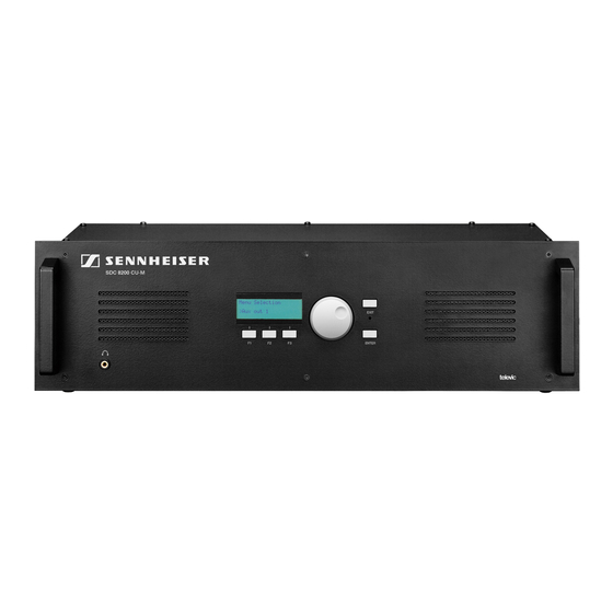
Page 25: The Sdc 8200 Cu-M Central Unit
The components of the SDC 8200 system in detail The SDC 8200 CU-M central unit Headphone output (3.5 mm mono jack socket) SLAVE IN socket (RJ 45) (not connected) Display SLAVE OUT socket (RJ 45) (not connected) F1 to F3 function keys... -
Page 26: The Sdc 8200 Ao Analog Output Unit (Optional)
POWER SUPPLY LED (lights up, if power is supplied to the SDC 8200 AO) SYNC. LED (lights up, if the data exchange between the central unit and the SDC 8200 AO functions correctly) FLOOR LED (lights up, if the floor channel is being used) -
Page 27: The System Cables
10 central units for setting up a large conference and interpretation system, connect an SDC 8200 AO analog output unit to the central unit, connect cable strings to the central unit. The system cables must meet the following specifications:... -
Page 28: Operating The Components Of The Sdc 8200 System
Operating the components of the SDC 8200 system Operating the components of the SDC 8200 system Depending on the type of delegate unit, conference participants can: listen, take the floor or make a request to speak, receive simultaneous interpretation, participate in voting sessions. - Page 29 Operating the components of the SDC 8200 system In “Fifo” mode: In this mode, the speaker limit is 1. Press the microphone key Pressing the microphone key on your console will automatically turn off the microphone of the previous speaker (“first-in-first-out”...
- Page 30 The chairman units and VIP units remain unaffectedly active. “No request” mode: For this mode to function, the SDC 8200 system must be PC controlled. In “No request” mode, you have to “apply” for a comment and wait until the conference manager turns on your microphone. The conference manager has total control of the microphones.
- Page 31 “With request” mode: In this mode, the SDC 8200 system can be controlled either by the chairman or via the PC. You can cancel your request to speak. The chairman can use the NEXT key...
-
Page 32: Turning Off The Microphone / Cancelling A Request To Speak
Adjusting the volume of the headphones connected to a conference console With conference consoles which feature two headphone outputs but only one volume control (SDC 8200 C, SDC 8200 CC, SDC 8200 DV and SDC 8200 CV), the volume control adjusts the volume for both connected headphones. -
Page 33: Selecting An Interpretation Channel
Selecting an interpretation channel If your console is equipped with channel selection keys (SDC 8200 DC, SDC 8200 CC, SDC 8200 DV and SDC 8200 CV), you can choose between the floor channel and the offered interpretation channels. To select an interpretation channel: Connect Sennheiser mono headphones to your conference console. -
Page 34: Using The Chip Card Slot Of A Conference Console
Operating the components of the SDC 8200 system Vote 1 of 5 In “Vote 1 of 5” mode, you have the choice of five options (1 to 5): Mic N.: 1024 VOTE 1 OF 5 To cast your vote, press the corresponding key below the display. -
Page 35: Operating The Chairman Unit
PC with software control is connected to the central unit – the conference manager. With the SDC 8200 CV chairman unit with voting function, you can start a voting session as follows: Choose one of the two voting modes “1 of 3” or “1 of 5” by pressing Mic N.: 0001... -
Page 36: Assigning A Participant The "Speaking Right
If the SDC 8200 CV chairman unit is configured so that the request-to- speak list is shown on the display, this request-to-speak list is also shown... -
Page 37: Operating The Interpreter Consoles
” menu selection key. The request-to-speak list is shown on the displays of all SDC 8200 DV and SDC 8200 CV conference consoles. The microphone numbers of the consoles from which a request to speak has been made are not shown on the displays of the SDC 8200 CV conference consoles. -
Page 38: Adjusting The Volume Of The Interpreter Consoles' Built-In Loudspeakers
Operating the components of the SDC 8200 system Adjusting the volume of the interpreter consoles’ built-in loudspeakers To adjust the volume of the interpreter console’s built-in loudspeaker, proceed as follows: Turn the control to adjust the volume of the console’s built-in loudspeaker. -
Page 39: Using The Interpreter Console
Operating the components of the SDC 8200 system Using the interpreter console As soon as your interpreter console is configured, you can use it as follows: Make sure that the correct channel for the target language is set (see “Switching between the A-channel and the B-channel” on page 39): If you interpret into the main target language assigned to your booth, choose the A-channel. -
Page 40: Displaying Text Messages On The Interpreter Console's Display
Before a conference starts, you have to configure your entire conference and interpretation system via the central unit’s operating menu (see “Configuring the SDC 8200 system” on page 61); it is, however, possible to make changes to individual settings during a conference. -
Page 41: The Menu Operating Controls
Operating the components of the SDC 8200 system Simultaneously press the F1 and F3 function keys and keeps them pressed for three seconds. If you release the two function keys after three seconds, the “key” symbol ( ) appears in the lower right corner of the display. The operating menu of the central unit is locked and you cannot change the settings of your conference. - Page 42 Operating the components of the SDC 8200 system Press the ENTER key Conference You get to the first main menu “ ”. Turn the jog wheel until the desired main menu is shown on the display and press the ENTER key You enter the desired main menu.
-
Page 43: Structuring The Sdc 8200 System
Per SDC 8200 CU central unit, you can connect up to 120 (6 x 20) consoles. Per SDC 8200 CU-M central unit, you can connect up to 50 (e.g. 5 x 10 or 3 x 15 + 1 x 5) consoles. -
Page 44: The Three Expansion Stages
Expansion stage (1) comprising one central unit with up to 20 consoles Expansion stage (2) comprising one SDC 8200 CU central unit with up to 120 consoles or one SDC 8200 CU-M central unit with up to 50 consoles Expansion stage (3) comprising several SDC 8200 CU central units with... -
Page 45: Expansion Stage (2): One Central Unit With Up To 120 Or 50 Consoles
In conference systems of expansion stage (2), up to six cable strings with up to 20 consoles each (6 x 20 = 120) can be connected to a single SDC 8200 CU central unit. This is the maximum number of consoles that can be connected to a single central unit. -
Page 46: Expansion Stage (3): Several Interconnected Sdc 8200 Cu Central Units With Up To 1024 Consoles
To set up a conference system with several central units, you first have to interconnect the consoles in cable strings and then connect the cable strings to the central units. Finally, you interconnect the central units (see “Interconnecting several central units (SDC 8200 CU central unit only)” on page 54). <=10 m <=10 m... -
Page 47: Calculating The Voltage Drop On The System Cables
This program can also be downloaded from www.sennheiser.com. Structuring an interpretation system If your SDC 8200 system comprises interpreter consoles, these are usually installed in acoustically isolated interpreter booths so that the interpreters cannot disturb each other or the audience. -
Page 48: Selectable Modes Between Or Within Interpreter Booths
Structuring the SDC 8200 system Selectable modes between or within interpreter booths With the SDC 8200 system, you can choose between three “modes between booths” and two “modes in booth”. Via the “modes between booths”, you fix the responsibilities of interpreters who are seated in different booths but interpret into the same target language (one on the A-channel and another on the B-channel). -
Page 49: Mode In Booths: "Mixed
Structuring the SDC 8200 system Mode in booths: “Mixed” Interpreters who are seated in the same booth and interpret into the same target language can activate their interpreter consoles any time by pressing the MIC key – even simultaneously. When two interpreters simultaneously interpret into the same target language, the red signal light ring and the “Microphone active”... - Page 50 Structuring the SDC 8200 system The below illustration shows the relay interpretation process (auto-floor). Russian AUTO-FLOOR German English If the original floor language is a language of which all interpreters have a complete understanding and from which they work, you...
-
Page 51: Using External Equipment
If you wish to output more channels, you require the optional SDC 8200 AO analog output unit. Connecting external audio sources Via the two XLR-3F sockets (AUX IN 1... -
Page 52: Transmitting The Floor Channel And The Interpretation Channels To Broadcasting And Tv Stations
Via the central unit’s XLR-3M audio output or via an audio output of the SDC 8200 AO analog output unit, you can connect a PA system via which the floor channel or an interpretation channel can be transmitted to e.g. -
Page 53: Setting Up The Sdc 8200 System
Connect the mains cable to the mains (100 – 240 V, 50 – 60 Hz). Rack-mounting several SDC 8200 CU central units For larger conference and interpretation systems with several SDC 8200 CU central units, we recommend mounting the central units into a rack. -
Page 54: Interconnecting The Consoles
You can only interconnect SDC 8200 CU central units. The length of the system cables between the SDC 8200 CU central units must not exceed 10 m. If you wish to interconnect several SDC 8200 CU central units, we recommend mounting the central units into a rack. -
Page 55: Turning The Interconnected Sdc 8200 Cu Central Units On And Off
Setting up the SDC 8200 system Turning the interconnected SDC 8200 CU central units on and off When turning on a conference and interpretation system with several central units, it is important that the central units are turned on in the correct order. -
Page 56: Connecting Additional Equipment
CU-M central unit, guests or participants can choose between the floor channel and up to four interpretation channels. Optionally, you can connect an SDC 8200 AO analog output unit to the central unit. The analog output unit features nine XLR-3M audio outputs... -
Page 57: Setting Up Remote Conferences
The signals of up to four interpretation channels are available at the outputs AUX OUT 2-3-4-5-6 of the 15-pole sub-D socket. If an SDC 8200 AO analog output unit is connected to the DATA OUT socket of the SDC 8200 CU central unit, additional channels can be output via the analog output unit’s XLR-3M audio outputs. -
Page 58: Connecting An Sdc 8200 Ao Analog Output Unit To The Sdc 8200 Cu Central Unit
Connecting several SDC 8200 AO analog output units to the SDC 8200 CU central unit To connect several SDC 8200 AO analog output units to the SDC 8200 CU central unit: Connect the DIGITAL BUS OUT socket of the first SDC 8200 AO to the DIGITAL BUS IN socket of the second SDC 8200 AO, and so on. -
Page 59: Connecting External Equipment To The Sdc 8200 Ao's Phoenix Connector
Setting up the SDC 8200 system Connecting external equipment to the SDC 8200 AO’s phoenix connector The SDC 8200 AO is fitted with a voltage-free contact (phoenix connector) which turns external equipment (e.g. a recording unit) on and off. When a console is active, the contact is closed and when no console is active, the contact is open. -
Page 60: Connecting A Pc To The Central Unit
Setting up the SDC 8200 system Connecting a PC to the central unit If your system comprises interpreter consoles, you require a PC with two serial interfaces: The conference management software accesses the conference configuration via the central unit’s COM 3 interface The interpreter management software accesses the interpreter configuration via the central unit’s COM 1 interface... -
Page 61: Configuring The Sdc 8200 System
Introduction to the central unit’s operating menu Via the central unit’s operating menu, the SDC 8200 conference and interpretation system can be configured for any room, any number of participants and any conference use. - Page 62 Configuring the SDC 8200 system The following overview shows how to navigate through the main menus. ENTER SDC 8200 Vx.xx >Volume = 1 Conference EXIT SDC 8200 Vx.xx EXIT 2 Interpretation SDC 8200 Vx.xx EXIT 3 Aux-In/Out SDC 8200 Vx.xx...
-
Page 63: The Submenus Of The "Conference" Menu (Part 1 Of 7)
Configuring the SDC 8200 system The submenus of the “Conference” menu (part 1 of 7) -
Page 64: The Submenus Of The "Conference" Menu (Part 2 Of 7)
Configuring the SDC 8200 system The submenus of the “Conference” menu (part 2 of 7) -
Page 65: The Submenus Of The "Conference" Menu (Part 3 Of 7)
Configuring the SDC 8200 system The submenus of the “Conference” menu (part 3 of 7) -
Page 66: The Submenus Of The "Conference" Menu (Part 4 Of 7)
Configuring the SDC 8200 system The submenus of the “Conference” menu (part 4 of 7) -
Page 67: The Submenus Of The "Conference" Menu (Part 5 Of 7)
Configuring the SDC 8200 system The submenus of the “Conference” menu (part 5 of 7) -
Page 68: The Submenus Of The "Conference" Menu (Part 6 Of 7)
Configuring the SDC 8200 system The submenus of the “Conference” menu (part 6 of 7) -
Page 69: The Submenus Of The "Conference" Menu (Part 7 Of 7)
Configuring the SDC 8200 system The submenus of the “Conference” menu (part 7 of 7) -
Page 70: The Submenus Of The "Interpretation" Menu (Part 1 Of 5)
Configuring the SDC 8200 system The submenus of the “Interpretation” menu (part 1 of 5) -
Page 71: The Submenus Of The "Interpretation" Menu (Part 2 Of 5)
Configuring the SDC 8200 system The submenus of the “Interpretation” menu (part 2 of 5) -
Page 72: The Submenus Of The "Interpretation" Menu (Part 3 Of 5)
Configuring the SDC 8200 system The submenus of the “Interpretation” menu (part 3 of 5) -
Page 73: The Submenus Of The "Interpretation" Menu (Part 4 Of 5)
Configuring the SDC 8200 system The submenus of the “Interpretation” menu (part 4 of 5) -
Page 74: The Submenus Of The "Interpretation" Menu (Part 5 Of 5)
Configuring the SDC 8200 system The submenus of the “Interpretation” menu (part 5 of 5) -
Page 75: The Submenus Of The "Aux-In/Out" Menu (Part 1 Of 8)
Configuring the SDC 8200 system The submenus of the “Aux-In/Out” menu (part 1 of 8) -
Page 76: The Submenus Of The "Aux-In/Out" Menu (Part 2 Of 8)
Configuring the SDC 8200 system The submenus of the “Aux-In/Out” menu (part 2 of 8) -
Page 77: The Submenus Of The "Aux-In/Out" Menu (Part 3 Of 8)
Configuring the SDC 8200 system The submenus of the “Aux-In/Out” menu (part 3 of 8) -
Page 78: The Submenus Of The "Aux-In/Out" Menu (Part 4 Of 8)
Configuring the SDC 8200 system The submenus of the “Aux-In/Out” menu (part 4 of 8) -
Page 79: The Submenus Of The "Aux-In/Out" Menu (Part 5 Of 8)
Configuring the SDC 8200 system The submenus of the “Aux-In/Out” menu (part 5 of 8) -
Page 80: The Submenus Of The "Aux-In/Out" Menu (Part 6 Of 8)
Configuring the SDC 8200 system The submenus of the “Aux-In/Out” menu (part 6 of 8) -
Page 81: The Submenus Of The "Aux-In/Out" Menu (Part 7 Of 8)
Configuring the SDC 8200 system The submenus of the “Aux-In/Out” menu (part 7 of 8) -
Page 82: The Submenus Of The "Aux-In/Out" Menu (Part 8 Of 8)
Configuring the SDC 8200 system The submenus of the “Aux-In/Out” menu (part 8 of 8) -
Page 83: The Submenus Of The "System" Menu (Part 1 Of 2)
Configuring the SDC 8200 system The submenus of the “System” menu (part 1 of 2) -
Page 84: The Submenus Of The "System" Menu (Part 2 Of 2)
Configuring the SDC 8200 system The submenus of the “System” menu (part 2 of 2) -
Page 85: The Submenus Of The "Language" And The "License" Menu (Part 1 Of 1)
Configuring the SDC 8200 system The submenus of the “Language” and the “License” menu (part 1 of 1) -
Page 86: Setting The Volume Of The Consoles' Built-In Loudspeakers
Configuring the SDC 8200 system Setting the volume of the consoles’ built-in loudspeakers The bars on the start display indicate the current volume setting for the consoles’ built-in loudspeakers. To set the volume of the consoles’ built-in loudspeakers: Turn the jog wheel on the central unit. -
Page 87: Manually Initializing All Conference Consoles
Configuring the SDC 8200 system Manually initializing all conference consoles If it is important that the conference consoles are assigned microphone numbers in a certain order, we recommend choosing the manual initialization. Conference From the central unit’s operating menu, choose “... -
Page 88: Removing A Conference Console From An Already Existing Configuration
Configuring the SDC 8200 system Add Unit Choose “ ”. Manual Init Only the signal light rings of the conference consoles not yet initialized Add Unit remain flashing. Press the microphone key of the conference consoles which you want to add to your configuration. -
Page 89: Selecting A Conference Mode
Configuring the SDC 8200 system To assign a reserved microphone number to a conference console to be added to an already existing configuration: Conference From the central unit’s operating menu, choose “ ”, Initialise Units Initialise Units Manual Init “... -
Page 90: Setting The Speaker Limit
Configuring the SDC 8200 system Setting the speaker limit You have to set the speaker limit, i.e. the max. number of speakers who can take the floor simultaneously, for the following conference modes: “No request” “With request” “With Req. No clear”... -
Page 91: Adjusting The Audio Settings For The Consoles' Microphones
Configuring the SDC 8200 system Adjusting the audio settings for the consoles’ microphones Microphones Via the “ ” menu item, you can adjust the audio settings Conference (bass, middle and treble response, automatic gain reduction, pick-up area Microphones around the microphone) for the consoles’ microphones. -
Page 92: Configuring Additional Chairman Units (Chairmen)
Configuring the SDC 8200 system Configuring additional chairman units (Chairmen) After initialization, the central unit determines one chairman unit. To configure additional chairman units (up to a maximum of 50 consoles), proceed as follows: Conference From the central unit’s operating menu, choose “... -
Page 93: Deleting The List Of Vip Units (Vip)
Configuring the SDC 8200 system Deleting the list of VIP units (VIP) You can delete the list of configured VIP units in order to configure other conference consoles as VIP units. Conference From the central unit’s operating menu, choose “... -
Page 94: Testing The Consoles' Microphones
Configuring the SDC 8200 system Testing the consoles’ microphones Test Units Via the “ ” menu item, you can check if the consoles’ microphones are working correctly To activate the microphones: Conference From the central unit’s operating menu, choose “... -
Page 95: Configuring The Interpretation System
Configuring the SDC 8200 system Configuring the interpretation system Apart from the conference system, the SDC 8200 system comprises a separate interpretation system. To be able to make use of the interpretation system, you require the SDC 8200 ID interpreter consoles. -
Page 96: Modifying The Currently Active Interpreter Configuration
Configuring the SDC 8200 system – if necessary – the second target language as described under “Configuring the second target language (B-channel) of a booth” on page 100. – if necessary – the auto-relay interpretation for the interpreters as described under “Enabling the auto-relay interpretation function (Auto-floor)”... -
Page 97: Loading A Previously Saved Interpreter Configuration
The operating mode within the interpreter booths You can connect a total of 28 booths with up to eight interpreter consoles each to a single central unit SDC 8200 CU, i.e. you can realize an interpretation system with up to 224 interpreter consoles. -
Page 98: Setting The Max. Number Of Interpreter Booths/Languages
(see “Licenses for expanding the SDC 8200 CU central unit” on page 117). Example: Let us assume that the active languages at a conference are English, German and French. -
Page 99: Configuring The Operating Mode Within A Booth
Configuring the SDC 8200 system language, the red signal light ring and the “Microphone active” on their consoles light up. Override Choose “ ” if activating an interpreter console in another booth turns off the currently active interpreter console. The... -
Page 100: Configuring The Main Target Language (A-Channel) Of A Booth
Configuring the SDC 8200 system Configuring the main target language (A-channel) of a booth To configure the main target language of a booth: From the central unit’s operating menu, choose “ Interpretation ”, Configuration Select Booth “ ” and “... -
Page 101: Enabling The Auto-Relay Interpretation Function (Auto-Floor)
Configuring the SDC 8200 system Enabling the auto-relay interpretation function (Auto-floor) If the original floor language is a language of which all interpreters have a complete understanding and from which they work, you do not have to enable this function. In this case, all interpreters interpret the original floor language into their respective target languages. -
Page 102: Manually Assigning An Interpreter Console An Individual Booth Number
Configuring the SDC 8200 system console, this console is intialized on the central unit with the booth and desk number shown on the console’s display. Start initializing the interpreter consoles by pressing the MIC key interpreter console 1 in booth 1. -
Page 103: Manually Assigning An Interpreter Console An Individual Desk Number (Interpreter Console Number)
Configuring the SDC 8200 system If all booth and desk numbers are assigned correctly, press the ENTER Full Init key on the central unit to save this configuration. Press ENTER to save The displays of the interpreter consoles show the languages assigned... -
Page 104: Displaying The Booth And Desk Number Of An Interpreter Console
Configuring the SDC 8200 system Note! The max. number of interpreter consoles per booth has to be configured via the central unit (see “Setting the max. number of interpreter consoles per booth” on page 98 and “Half-automatically initializing all interpreter consoles on the central unit” on page 101). -
Page 105: Resetting The Interpretation System
Configuring the SDC 8200 system To load the factory-preset default configuration for the interpretation system: Interpretation From the central unit’s operating menu, choose “ ”, Interpretation Initialise Units Load Default “ ” and “ s” one after the other. Initialise Units The text “... -
Page 106: Adjusting The Volume Of The Audio Outputs
This is a professional conference system. Commercial use is subject to the rules and regulations of the trade association responsible. Sennheiser, as the manufacturer, is therefore obliged to expressly point out possible health risks arising from use. This system is capable of producing sound pressure exceeding 85 dB(A). -
Page 107: Adjusting The Volume Differences Between The Aux Out 1 Outputs
AUX OUT 6 can be assigned a channel. The maximum number of channels available depends on your license. The configuration of four channels/languages is license-free. In order to be able to configure more than four channels/languages (SDC 8200 CU only), you have to purchase one of the language licenses available. Note! The floor channel is always assigned to the audio output AUX OUT 1. -
Page 108: Turning On/Off The Audio Inputs Or Outputs
This is a professional conference system. Commercial use is subject to the rules and regulations of the trade association responsible. Sennheiser, as the manufacturer, is therefore obliged to expressly point out possible health risks arising from use. This system is capable of producing sound pressure exceeding 85 dB(A). -
Page 109: Configuring The Audio Outputs For Remote Conferencing
Configuring the SDC 8200 system To adjust the volume difference between the headphone outputs: Aux-In/Out From the central unit’s operating menu, choose “ ” and Aux Out 6 Aux Out 6 “ ” one after the other. Volume Headphone Volume Headphone Choose “... -
Page 110: Adjusting The Input Level Of An Audio Input
Configuring the outputs of the SDC 8200 analog output unit You can configure the outputs of the SDC 8200 AO analog output unit via the two DIP switches and the rotary switch located on the printed circuit board of the SDC 8200 AO. For configuring the outputs, you have to open the analog output unit. - Page 111 Connect the second analog output unit as described in the section “Connecting several SDC 8200 AO analog output units to the SDC 8200 CU central unit” on page 58. The channels 9 to 16 are output via the outputs OUT 1 to OUT 8 of the analog output unit.
-
Page 112: Making A System Diagnosis
Configuring the SDC 8200 system Making a system diagnosis Displaying the number of consoles connected to the central unit To display the number of consoles connected to the central unit: System From the central unit’s operating menu, choose “ ”,... -
Page 113: Turning On A Connected Control Panel
Control Panel Status = OFF Press ENTER to Save Configuring an “ambient sound” console Optionally, you can use an “ambient sound” console with your SDC 8200 System conference and interpretation system. As soon as all other consoles in the Ambient Sound conference room are deactivated, the “ambient sound”... -
Page 114: Software, Language And License
Configuring the SDC 8200 system To turn the built-in loudspeaker of the “ambient sound” console on or off: System Ambient From the central unit’s operating menu, choose “ ”, “ Ambient Sound Sound Loudspeaker ” and “ ” one after the other. -
Page 115: Displaying The Central Unit's Serial Number
View License xxxx-xxxx-xxxx-xxxx Upgrading the license of your conference and interpretation system The SDC 8200 CU and SDC 8200 CU-M central units come with a basic license, allowing the configuration of four languages/interpretation channels as well as the “camera control” function. -
Page 116: If Problems Occur
If problems occur... If problems occur... Replacing a fuse If the fuse of a central unit has blown, the subsequent consoles cannot be powered. To replace the fuse: Use a screwdriver to carefully loosen the fuse holder and pull it out completely. -
Page 117: Accessories
Chairman unit with voting function 009849 SDC 8000 CARD Chip card 500866 SDC 8200 ID Interpreter console Software for PC controlling the SDC 8200 CU central unit 500975 SDC 8200 SYS 502053 SDC 8200 SYS CD-ROM update 500976 SDC 8200 S-MM Software module “Mic Management”... -
Page 118: Specifications
Specifications Specifications Features of the central units Features SDC 8200 CU SDC 8200 CU-M Max. number of consoles Operation of the SDC 8200 DV delegate unit max. number of connectable – Analog output units Daisy-chainable expandable by additional licenses Voting modes... -
Page 119: Sdc 8200 C
Specifications SDC 8200 C Frequency response 100 – 14,000 Hz Pick-up pattern cardioid 3.5 mm mono jack socket (≥ 16 Ω) Headphone output Maximum output level 1.5 V at 32 Ω at headphone output S/N at headphone output > 75 dBA Power consumption max. -
Page 120: Sdc 8200 Cc
Specifications SDC 8200 CC Frequency response 100 – 14,000 Hz Pick-up pattern cardioid 3.5 mm mono jack socket (≥ 16 Ω) Headphone output Maximum output level 1.5 V at 32 Ω at headphone output S/N at headphone output > 75 dBA Power consumption max. -
Page 121: Sdc 8200 Cv
Specifications SDC 8200 CV Frequency response 100 – 14,000 Hz Pick-up pattern cardioid 3.5 mm mono jack socket (≥ 16 Ω) Headphone output Maximum output level 1.5 V at 32 Ω at headphone output S/N at headphone output > 75 dBA Power consumption max. -
Page 122: Sdc 8200 Cu Central Unit
Specifications SDC 8200 CU central unit AUX IN 1,2 XLR-3F, transformer balanced Input level max. +14 dBu Input impedance > 6 kΩ at 1 kHz Frequency response 100 – 14,000 Hz AUX OUT 1 XLR-3M, transformer balanced Output level max. +6 dBu <... -
Page 123: Sdc 8200 Ao Analog Output Unit
Specifications SDC 8200 AO analog output unit Power supply 48 V DC supplied via SDC 8200 CU DATA OUT port Frequency response 100 – 14,000 Hz Output level (XLR) max. 0 dBu, balanced Output level (RCA): max. 0 dBu, unbalanced ≤... -
Page 124: Appendix A: Camera Control Protocol
None The syntax of the commands All commands sent by the SDC 8200 CU central unit start with a “%” sign. The last character is a character which states the end of the transmission. Just before the end-of-transmission character, there are four characters within the command sent to the camera control which account for the CRC checksum. - Page 125 Appendix A: Camera control protocol...
-
Page 126: Commands
Appendix B: Control panel protocol Appendix B: Control panel protocol The SDC 8200 conference and interpretation system supports a control panel. The central unit sends a control command to the connected control panel: when a delegate or chairman unit is activated,... -
Page 127: The Commands Sent By The Central Unit And Received By The Control Panel
Appendix B: Control panel protocol... -
Page 128: Appendix C: Repeater For The Sdc 8200 System
Appendix C: Repeater for the SDC 8200 system Appendix C: Repeater for the SDC 8200 system A repeater is used to boost the signal on a system cable. When a system cable reaches a length of 100 m, the signal over the system cables becomes too weak. -
Page 129: Manufacturer Declarations
Manufacturer declarations Manufacturer declarations Warranty regulations The guarantee period for this Sennheiser product is 24 months from the date of purchase. Excluded are accessory items, rechargeable or disposable batteries that are delivered with the product; due to their characteristics these products have a shorter service life that is principally dependent on the individual frequency of use. - Page 130 Sennheiser electronic GmbH & Co. KG 30900 Wedemark, Germany Phone +49 (5130) 600 0 Fax +49 (5130) 600 300 www.sennheiser.com Printed in Germany Publ. 07/06 516540/A01...
Need help?
Do you have a question about the SDC 8200 and is the answer not in the manual?
Questions and answers