Table of Contents
Advertisement
Quick Links
Advertisement
Table of Contents

Subscribe to Our Youtube Channel
Related Manuals for Sennheiser ADN Series


Summary of Contents for Sennheiser ADN Series
- Page 1 Audio Distribution Network System instruction manual...
-
Page 2: Table Of Contents
Contents Contents Important safety instructions ..................4 The Sennheiser ADN conference system ..............7 Available system components – package contents ......................8 Overview of the components ................... 10 ADN D1 delegate unit ....................12 ADN C1 chairperson unit ..................... 13 ADN-W D1 wireless delegate unit ................ - Page 3 Contents Setting up the ADN-W C1 or ADN-W D1 wireless conference units ....74 Connecting external audio devices to the central unit ......... 75 Connecting a USB mass storage device for audio recordings to the central unit .. Preparing to use the “Conference Manager” software ......... 76 Switching the conference system on/off ..............
- Page 4 Contents Updating the firmware of the conference system ..........230 If a problem occurs .../Frequently asked questions ..........231 Components and accessories .................. 237 Specifications ......................240 Appendix ........................248 Mounting dimensions ....................248 RF channels and transmission powers for wireless conferencing ....251 Factory default settings ....................
-
Page 5: Important Safety Instructions
Important safety instructions Important safety instructions 1. Read this system manual. 2. Keep this system manual. Always include the system manual when passing the apparatus on to third parties. 3. Heed all warnings. 4. Follow all instructions. 5. Do not use the apparatus near water. 6. - Page 6 Never open the ADN CU1 central unit, the ADN PS power supplies, the ADN-W L10 chargers and the ADN-W CASE UNITS as there is a risk of electric shock. There are no user serviceable parts inside. Refer servicing to an authorized Sennheiser ser- vice partner.
- Page 7 • an explosion hazard, • a smoke or gas hazard. Please understand that Sennheiser does not accept liability for damage arising from abuse or misuse. Keep away from children. Do not pack charged battery packs loose. Observe correct polarity.
-
Page 8: The Sennheiser Adn Conference System
The Sennheiser ADN conference system The Sennheiser ADN conference system Sennheiser ADN stands for Sennheiser Audio Distribution Network – the new gen- eration of digital conference equipment. The ADN conference system has been designed for maximum versatility and can be easily adapted to many different requirements. -
Page 9: Available System Components - Package Contents
Available system components – package contents Available system components – package contents ADN wired standard components ADN CU1 central unit 1 ADN CU1 central unit 1 mains cable (with EU, UK or US mains plug, depending on version), length 1.8 m 1 instruction manual 1 “Safety information”... - Page 10 Available system components – package contents NT 12-50C power supply Power supply for charging one ADN-W BA or for optionally powering the ADN-W AM antenna module 1 NT 12-50C power supply 1 mains cable (with EU, UK or US mains plug, depending on version), length 2.5 m 1 instruction manual ADN-W L 10 charger 1 ADN-W L 10 charger...
-
Page 11: Overview Of The Components
Overview of the components Overview of the components Components required for setting up a wired conference system: • 1 ADN CU1 central unit • ADN D1 delegate units (a maximum of 400 delegate units can be used in a conference system) •... - Page 12 Overview of the components Components required for setting up a wireless conference system: • 1 ADN CU1 central unit • at least 1 ADN-W AM antenna module for operating the wireless conference units • ADN-W D1 wireless delegate units (a maximum of 150 delegate units can be used in a conference system) •...
-
Page 13: Adn D1 Delegate Unit
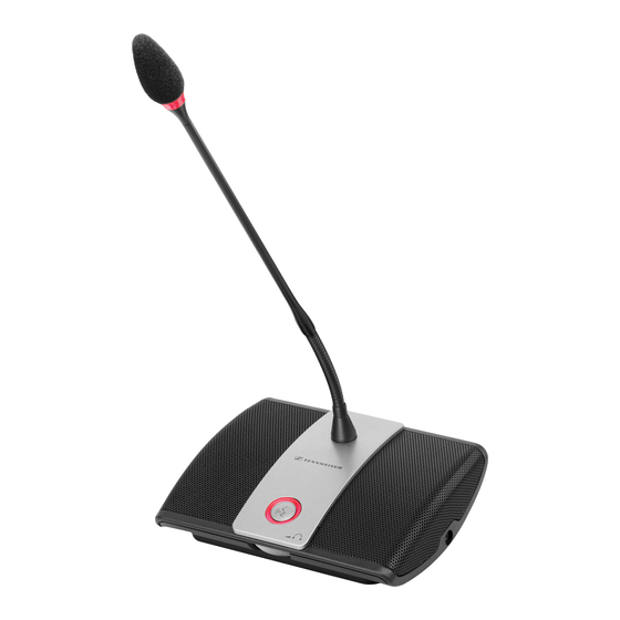
Overview of the components ADN D1 delegate unit < Sound inlet basket with glued socket windshield socket Signal light ring Type plate (see bottom) Headphone socket Headphone volume control for headphone socket Microphone key Microphone LED Loudspeaker 12 | ADN Digital Conference System... -
Page 14: Adn C1 Chairperson Unit
Overview of the components ADN C1 chairperson unit < Sound inlet basket with glued socket windshield socket Signal light ring Type plate (see bottom) Headphone socket Priority key Next key Headphone volume control for headphone socket Microphone key Microphone LED Loudspeaker ADN Digital Conference System | 13... -
Page 15: Adn-W D1 Wireless Delegate Unit
Overview of the components ADN-W D1 wireless delegate unit < < < < Sound inlet basket with glued Guide rails for ADN-W BA windshield battery pack Signal light ring Connection for ADN-W BA battery pack Headphone socket Type plate Headphone volume control for headphone socket Microphone key Microphone LED... -
Page 16: Adn-W C1 Wireless Chairperson Unit
Overview of the components ADN-W C1 wireless chairperson unit < < < < Sound inlet basket with glued Guide rails for ADN-W BA windshield battery pack Signal light ring Connection for ADN-W BA battery pack Headphone socket Type plate Priority key Next key Headphone volume control for headphone socket... -
Page 17: Adn-W Ba Lithium-Ion Battery Pack
Overview of the components ADN-W BA Lithium-Ion battery pack Rechargeable Lithium-Ion Battery Pack ADN-W BA Art.No.: 504744 Ser.-No.: Rated Voltage/Capacity/Energy: 7.4V/7.8Ah/57.72Wh Charge Voltage/Current: 12V/2.5A 2ICR19/65-3 LISTED LI-ION MADE IN POLAND Battery status indicator Button for charge status indication RF status indicator Charge status indicator Charging contacts for Contacts for connection to... -
Page 18: Adn-W Mic 15/Adn-W Mic 36 Gooseneck Microphones For Wireless Conference Units
Overview of the components ADN-W MIC 15/ADN-W MIC 36 gooseneck microphones for wireless conference units ADN-W MIC 15-39 = 39 cm ADN-W MIC 15-50 = 50 cm ADN-W MIC 36-29 = 29 cm ADN-W MIC 36-50 = 50 cm Sound inlet basket with glued Fastening thread windshield Sliding contacts for connection to... -
Page 19: Adn-W Am Antenna Module
Overview of the components ADN-W AM antenna module 95 mm Hole for safety wire Antenna coupling ring Cable grip Mounting holes for wall mounting Output socket 5/8" mounting thread with 3/8" thread insert Input socket > Rubber feet Hollow jack socket for connection of optional NT 12-50C power supply Type plate Antennas... -
Page 20: Nt 12-50C Power Supply
Overview of the components NT 12-50C power supply The power supply can charge one ADN-W BA battery pack or can optionally power the ADN-W AM antenna module. NT 12-50C Mains cable with mains plug Euro 8 socket for mains cable (with EU, UK or US mains plug, depending on version) Hollow jack plug... -
Page 21: Adn Cu1 Central Unit
Overview of the components ADN CU1 central unit ADN CU1 IN –– AUDIO –– OUT PORT II PORT I 100-240V~ 50/60Hz 240W 2x 52.8V 1.75A A Front view B Rear view On/off switch audio input Standard display key audio output Display PORT II socket (RJ45) for... - Page 22 Overview of the components Overview of the ADN CU1 display panel After switch-on, the central unit’s display panel shows progress bars (for the boot- ing routine “Booting...” and the self test “Self-Test...”) and then the standard display: Direct Access 30 D1/C1 Text/icon Possible display/function Conference mode...
-
Page 23: Conference Manager" Software
Overview of the components “Conference Manager” software The “Conference Manager” software allows you to configure and control the entire conference from a Windows PC or directly from the ADN CU1 central unit. Information on the software can be found in the chapter “Using the “Conference Manager”... -
Page 24: Adn Ps Power Supply
Overview of the components ADN PS power supply ADN PS PORT I PORT II DATA CU/PS 100 - 240V 50/60Hz 385W PORT I & PORT II: max. 5.25A sum A Front view B Rear view Rack mount “ears” PORT I socket –... -
Page 25: Sdc Cbl Rj-45 System Cables
Overview of the components SDC CBL RJ-45 system cables The system cables transmit the digital audio and status information and supply power to the conference units and to the antenna module. use unshielded Cat5 cable (26 AWG)! Shielded RJ 45 modular plug, Cat5(e) Gray cable booth with clip protector Round STP cable, cat 5(e), 24AWG, black Black cable booth with clip protector... - Page 26 Overview of the components Overview of the status display of the ADN-W L 10 and ADN-W CASE UNITS The status display for charging process consists of 10 LEDs. The button allows you to switch between two charge status indications to view the obtained capacity: 1.
-
Page 27: Adn-W Case Transport And Charging Case
Overview of the components ADN-W CASE transport and charging case ADN-W CASE UNITS charging case ADN-W CASE BASE case lid with charging compartments for ADN-W CASE CENTRAL transport case 10 wireless conference units for central unit, antenna module, ADN- W L 10 charger, power supplies, mains ADN-W CASE BASE case bottom cables and other accessories with wheels... - Page 28 Overview of the components ADN-W CASE UNITS charging case < ADN-W CASE UNITS Art.-No.: 504956 Ser.-No.: XXXXXXXXXX ~100-240V, 50/60Hz Max. Power Consumption: 250 W CAUTION / AVIS RISK OF ELECTRIC SHOCK - DO NOT OPEN RISQUE DE CHOC ELECTRIQUE - NE PAS OUVRIR MADE IN GERMANY Charging compartments for 10 wireless Mains socket...
-
Page 29: Structuring And Controlling The Conference System
The software is included on the DVD-ROM (supplied with the ADN CU1) or is available from your Sennheiser part- ner or from the “Downloads” area on the product page at www.sennheiser.com. -
Page 30: Setting Up A Wired Conference System
Structuring and controlling the conference system Setting up a wired conference system Basic requirements for a conference system comprising wired conference units For safe operation of the conference system, make sure that all wired conference units are supplied with a voltage of at least 35 V! The voltage supplied depends on the number of connected conference units and on the cable lengths. - Page 31 Structuring and controlling the conference system Large conference system with simple cabling For setting up a large conference system with the maximum number of conference units (i.e. up to 400), you require one ADN CU1 central unit for controlling the con- ference and additional ADN PS power supplies for powering the conference units.
- Page 32 Structuring and controlling the conference system Large conference system with redundant ring topology The redundant ring topology ensures that, should one conference unit or system cable fail or be manipulated, all other conference units of the cable ring will con- tinue to function reliably.
-
Page 33: Setting Up A Wireless Conference System
Structuring and controlling the conference system Setting up a wireless conference system Basic requirements for a conference system comprising wireless conference units The ADN-W C1 and ADN-W D1 wireless conference units connect wirelessly to the ADN-W AM antenna module, which is connected to the ADN CU1 central unit via a system cable. -
Page 34: Combining Wired And Wireless Conference Units (Hybrid Operation)
Structuring and controlling the conference system Combining wired and wireless conference units (hybrid operation) ADN C1 and ADN D1 wired conference units and ADN-W C1 and ADN-W D1 wireless conference units can be combined arbitrarily (hybrid operation) as long as you ensure correct set-up and cabling and comply with the specifications (see page 56). -
Page 35: Configuring And Controlling The Conference System
Structuring and controlling the conference system Configuring and controlling the conference system For configuring the conference system, you can either use the operating menu of the central unit or the “Conference Manager” software. However, the full function- ality of a wireless conference system can only be configured using the “Conference Manager”... -
Page 36: Using The Adn Cable Calculator Software
Using the ADN Cable Calculator software Using the ADN Cable Calculator software “ADN Cable Calculator” software allows you to calculate the voltage supply on the individual sections of a cable string or cable ring. If you want to use wireless conference units in your conference system, you also have to calculate the voltage needed to power the ADN-W AM antenna module in order to ensure that all com- ponents are supplied with sufficient voltage. - Page 37 Using the ADN Cable Calculator software Click the “Next” button. A selection window for specifying the installation location appears: Use the default or select an installation path. Click the “Next” button. A summary of the selected installation settings is displayed: Confirm this summary by clicking the “Next”...
-
Page 38: Using The Adn Cable Calculator
Using the ADN Cable Calculator software Using the ADN Cable Calculator To use the “ADN Cable Calculator” software and to calculate the cable lengths and number of conference units: Start the “ADN Cable Calculator” software from the Start menu or the shortcut on your desktop. -
Page 39: Putting The Conference System Into Operation
Putting the conference system into operation Putting the conference system into operation Preparing the ADN CU1 central unit for operation Setting up the central unit on a flat surface or mounting it into a rack If you want to place the central unit on a flat surface: Make sure that the air vents are not covered or blocked. - Page 40 Putting the conference system into operation Fastening the optional Unscrew and remove the 2 torx screws (T25) on each side of the central unit rack mount “ears” (see left-hand diagram). Secure the optional ADN RMB-2 rack mount “ears” (see “Components and accessories”...
-
Page 41: Preparing The Adn Ps Power Supply For Operation
Putting the conference system into operation Preparing the ADN PS power supply for operation If you want to place the ADN PS power supply on a flat surface: CAUTION Danger of material damage and personal injury due to stacked power supplies! When stacking several ADN PS power supplies on top of each other, •... - Page 42 Putting the conference system into operation If you want to mount the ADN PS power supply into a 19" rack: CAUTION Danger of material damage and personal injury when rack mount- ing the power supply! When installing the product in a closed or multi-rack assembly, please consider that, during operation, •...
-
Page 43: Preparing The Adn-W Am Antenna Module For Operation
Putting the conference system into operation Preparing the antenna module for ADN-W AM operation The antenna module is powered from the ADN CU1 central unit or the ADN PS power supply via the SBC CBL RJ45 system cable. If the power supplied via the system cable is not sufficient and if the antenna module is not listed in the central unit‘s operating menu under “System Menu”... - Page 44 Putting the conference system into operation Connecting the ADN-W AM antenna module to the mains power supply Using the “ADN Cable Calculator” software, calculate if you require an additional power supply for the antenna module (see page 35). If the power supplied to the antenna module via the SBC CBL RJ45 system cable is not sufficient, you have to power the antenna module using the optional NT 12-50C power supply.
-
Page 45: Preparing The Adn C1/Adn D1 Wired Conference Units For Operation
Putting the conference system into operation Preparing the ADN C1/ADN D1 wired conference units for operation The conference units are ready for operation upon delivery. The conference system automatically recognizes if the connected conference units are chairperson units (ADN C1) or delegate units (ADN D1) and initializes them automatically. To ensure full operational reliability in a redundant ring topology, the hard- ware of the ADN C1 and ADN D1 has been revised. - Page 46 Putting the conference system into operation Hold the conference units with one hand so that the microphone does not rest on the table. Insert the cable holder as shown. At this point, the cable holder not yet fixed with screws. You first have to connect the conference units as described in the chapter “Setting up the con- ference system”...
-
Page 47: Preparing The Adn-W C1/D1 Wireless Conference Units For Operation
Putting the conference system into operation Preparing the ADN-W C1/D1 wireless conference units for operation To operate the wireless conference unit, you have to connect a gooseneck micro- phone (ADN-W MIC 15 or ADN-W MIC 36; available in different lengths) to the con- sole of the conference unit. - Page 48 Putting the conference system into operation Inserting/removing the battery pack insert the ADN-W BA battery pack into the wireless conference unit: Check the battery pack before using it in order to ensure sufficient battery capacity and to exclude a defective battery pack (see page 51). Charge the battery pack if necessary (see page 51).
-
Page 49: Preparing The Adn-W L 10 Charger For Operation
Putting the conference system into operation Preparing the ADN-W L 10 charger for operation The ADN-W L 10 charger allows you to simultaneously charge up to 10 ADN-W BA Lithium-Ion battery packs. You can set up the charger on a flat surface or mount it into a 19"... -
Page 50: Preparing The Adn-W Case Units Charging Case For Operation
Putting the conference system into operation Connecting the charger to and disconnecting it from the mains power supply CAUTION Product damage due to an unsuitable power supply! If you connect the charger to an unsuitable power supply, this can cause damage to the device. - Page 51 Putting the conference system into operation If necessary, lock the casters of the ADN-W CASE BASE case bottom in place by pushing the locking lever downwards (see page 227). Unlock Lock Connecting the charging case to and disconnecting it from the mains power supply CAUTION Product damage due to an unsuitable power supply!
-
Page 52: Charging The Adn-W Ba Battery Pack
Putting the conference system into operation Charging the ADN-W BA battery pack The ADN-W BA battery pack can be charged: • while it is inserted in the wireless conference unit using the NT 12-50C power supply – even during operation •... - Page 53 Putting the conference system into operation During operation, the battery status indicator additionally indicates when the battery pack is almost flat. Status LEDs Color Meaning Battery status indicator – Battery capacity 5-100% orange, flashing slowly Battery capacity < 5%, battery pack is almost flat orange, flashing rapidly Battery pack is defective Charging the battery pack using the NT 12-50C power supply Using the NT 12-50C power supply, you can charge the ADN-W BA battery pack...
- Page 54 Putting the conference system into operation Insert the battery pack into any charging compartment until it locks into place. The battery pack is being charged (see “Behavior of the ADN-W BA battery pack during charging” on page 55). The status display indicates the charging process (see “The status display of the ADN-W L 10/ADN-W CASE UNITS charger during charging”...
- Page 55 Putting the conference system into operation Switching off the ADN-W L 10/ADN-W CASE UNITS charger To switch off the ADN-W L 10/ADN-W CASE UNITS charger after use: Set the on/off switch of the charger to position “0”. The charger switches off. The operation indicator goes off. To disconnect the ADN-W L 10/ADN-W CASE UNITS charger from the mains power supply: Pull out the mains plug from the wall socket.
- Page 56 Putting the conference system into operation Behavior of the ADN-W BA battery pack during charging When charging the battery pack using the NT 12-50C power supply or the ADN-W L10 or ADN-W CASE UNITS chargers, the battery pack and the corresponding char- ger will get warm.
-
Page 57: Setting Up The Conference System
Putting the conference system into operation Setting up the conference system CAUTION Product damage due to an unsuitable power supply! If you connect standard network devices with RJ45 plugs (e.g. switches or network cards) to the connection sockets PORT I PORT DATA PS , the net-... - Page 58 Putting the conference system into operation Setting up a small wired conference system with only the central unit For a small wired conference system, you do not require ADN PS power supplies. Connecting conference units The following describes how to connect one cable string to the ADN CU1 central connected in a cable string to the unit.
- Page 59 Putting the conference system into operation Setting up a large wired conference system with ADN PS power supplies connected to the ADN CU1 central unit For conference systems comprising more than 40 conference units or when the conference units are connected in a redundant ring topology, you require ADN PS power supplies.
- Page 60 Putting the conference system into operation ADN PS ADN D1/ADN C1 PORT I PORT II DATA CU/PS 100 - 240V 50/60Hz 385W PORT I & PORT II: max. 5.25A sum < 6 7 8 9 PORT I PORT II IN OUT IN OUT IN OUT PORT I...
- Page 61 Putting the conference system into operation Setting up a large conference system comprising ADN PS power supplies and conference units connected in redundant ring topology In large conference systems with up to 400 conference units, the redundant ring topology ensures that, should one conference unit or system cable fail or be manip- ulated, all other conference units of the cable ring will continue to function reliably.
- Page 62 Putting the conference system into operation ADN PS ADN D1/ADN C1 PORT I PORT II DATA CU/PS 100 - 240V 50/60Hz 385W PORT I & PORT II: max. 5.25A sum < 6 7 8 9 PORT I PORT II IN OUT IN OUT IN OUT PORT I...
- Page 63 Putting the conference system into operation Cabling errors If the cabling is wrong, the system may perhaps function, but operational reliability is compromised and monitoring cannot be carried out reliably. Therefore, avoid the following severe cabling errors: Audio Distribution Network Processing ...
- Page 64 Putting the conference system into operation DATA socket of an ADN PS power DATA PS output socket of an ADN PS power supply connected to supply must not be connected to a PORT socket. a PORT I/II socket of The error message “Error 60004 PS unit at PS an ADN PS power supply conference...
- Page 65 Putting the conference system into operation Ring topology connected to A ring topology cannot be connected to different PORT different PORT sockets of sockets of an ADN PS power supply. an ADN PS power supply The error message “Error 60005 Ring cabling between port I+II”...
- Page 66 Putting the conference system into operation Ring topology connected to the The ring topology is connected to the wrong outputs of a PORT socket wrong outputs of the PORT socket. The conference units connected in the cable ring do not function and are not displayed in the “Units”...
-
Page 67: Connecting The Adn-W Am Antenna Module To The Adn Cu1 Central Unit
Putting the conference system into operation Connecting the ADN-W AM antenna module to the ADN CU1 central unit For operating the wireless conference units, you require at least one ADN-W AM antenna module. Use a system cable (supplied with the ADN-W AM; the maximum cable length allowed is 50 m) to connect the PORT II socket... - Page 68 Putting the conference system into operation To optionally combine the antenna module with wired conference units (hybrid operation), connect the antenna module just like a wired conference unit: Use a system cable to connect the output socket of the ADN-W AM <...
- Page 69 Putting the conference system into operation ADN-W AM antenna module No antenna module must be connected to the DATA connected to the DATA socket of the output socket of an ADN PS power supply. ADN PS power supply The error message “Error 60010 AM at PS cascading port”...
-
Page 70: Setting Up And Positioning The Antenna Module
Putting the conference system into operation Setting up and positioning the antenna module CAUTION Danger of injury and material damage! If improperly installed or insufficiently fixed, the antenna module can fall from the wall, ceiling or stand or tip over and can cause injury or material damage. - Page 71 Putting the conference system into operation Set up the devices so that there is a “free line of sight” between the wireless conference units and the antenna module. Place the antenna module as centrally as possible and above the wireless con- ference units.
- Page 72 Putting the conference system into operation Wall mounting is recommended for rooms with a ceiling height of more than 10 m because the wireless conference units have an omni-directional radiation pattern (approx. 30 m): Mount the antenna module to the wall at a height of max. 10 m from the floor. To do so, use the optional GZG 1029 swivel joint and GZP 10 mounting plate (see “Mounting the antenna module to the ceiling”...
- Page 73 Putting the conference system into operation To protect the antenna module from accidental dropping: Guide a safety wire through the hole for safety wire and attach the safety wire e.g. to a separate hook. M4 x 25 Mounting the antenna module to the ceiling For ceiling mounting, use the optional GZG 1029 swivel joint and GZP 10 mounting plate.
- Page 74 Putting the conference system into operation Screw the antenna module to the stand using the mounting thread " " " Placing the antenna module on a flat surface Place the antenna module on a flat surface. Orienting the antennas Orient the 3 antennas so that they are parallel to each other and are directed at a 90°...
-
Page 75: Setting Up The Adn-W C1 Or Adn-W D1 Wireless Conference Units
Putting the conference system into operation Setting up the ADN-W C1 or ADN-W D1 wireless conference units CAUTION Danger of intermodulation! If you set up the ADN-W C1 or ADN-W D1 wireless conference units and the ADN-W AM antenna module too close to one another, intermodulation can occur. Observe a minimum distance: –... -
Page 76: Connecting External Audio Devices To The Central Unit
Putting the conference system into operation Connecting external audio devices to the central unit You can use different settings for processing the audio signals of the audio input and the audio output in order to avoid, for example, delayed or double audio signals in videoconferencing or teleconferencing systems (see page 100 or page 201). -
Page 77: Preparing To Use The "Conference Manager" Software
Putting the conference system into operation Preparing to use the “Conference Manager” software Running the software installed on the central unit To use the “Conference Manager” software installed on the central unit, you require the following devices: Device Requirements Screen Connection: 15-pin Sub-D VGA Resolution:... -
Page 78: Switching The Conference System On/Off
Putting the conference system into operation Switching the conference system on/off The ADN PS power supplies and the ADN-W AM antenna module can only be switched on when the central unit ADN CU1 and the previous ADN PS connected in series are also switched on. ADN PS ADN PS ADN CU1... - Page 79 Putting the conference system into operation Switching on a conference system comprising an antenna module for wireless operation Switching on the central unit and the Set the on/off switch of the ADN CU1 central unit to position “I”. antenna module The central unit switches on and its display panel lights up.
- Page 80 Putting the conference system into operation To switch off the ADN-W AM antenna module: Disconnect the system cable from the input socket of the antenna module. The antenna module is switched off. All previously connected wireless confer- ence units try to reconnect to the antenna module and automatically switch off after 5 minutes if no switched-on antenna module can be found.
-
Page 81: Using The Media Control System
PDF doc- ument “ADN_MediaCtrl_Protocol.pdf” included on the DVD-ROM (supplied with the central unit) or at www.sennheiser.com. For more questions on the integration of the ADN conference system into a media control system, contact your Sennheiser partner. -
Page 82: Configuring The Wireless Components
Configuring the wireless components Configuring the wireless components CAUTION Risk of violation of legal requirements! If you are using radio frequencies and transmission powers that cannot be used license-free in your country, there is a risk of violation of legal requirements. Use only radio frequencies and transmission powers that are approved and legal in your country. - Page 83 Configuring the wireless components Checking the RF signal quality During operation, you can check the RF signal quality of a wireless conference unit via the RF status indicator of the respective conference unit or via the “Conference Manager” software (see also “Reducing transmission interference” on page 82). ADN-W BA •...
-
Page 84: Using The Central Unit
Using the central unit Using the central unit Deactivating the lock mode of the central unit If the lock mode is activated (see page 114), you have to deactivate it in order to be able to operate the central unit: Press the jog dial or any other key. -
Page 85: Configuring The Conference System Via The Central Unit
Configuring the conference system via the central unit Configuring the conference system via the central unit Overview of the operating menu “XLR Out” “Conference Menu” submenu submenu XLR Out Status Conference Mode XLR Out Volume Microphone Limit XLR Out Equalizer Request Limit Talk Time Status Talk Time Limit... - Page 86 Configuring the conference system via the central unit Display Function of the menu item Option/display page “Main Menu” “Conference Menu” Calls up the “Conference Menu” submenu – “Audio Menu” Calls up the “Audio Menu” submenu – “Wireless Menu” Calls up the “Wireless Menu”...
- Page 87 Configuring the conference system via the central unit Display Function of the menu item Option/display page “Conference Recording” Calls up the “Conference Recording” submenu – “XLR Out” menu “XLR Out Status” Activates/deactivates the audio output “On”/“Off” “XLR Out Volume” Adjusts the volume of the XLR output XLR Out Volume + 6 dB + 6 dB...
- Page 88 Configuring the conference system via the central unit Display Function of the menu item Option/display page “Conference Recording” menu “Record” Starts/stops the audio recording of the conference “On”/“Off” channels on a USB mass storage device “Recording Status” Provides information on the status of the audio Recording Status Status : Off...
-
Page 89: Working With The Operating Menu
Configuring the conference system via the central unit Display Function of the menu item Option/display page “Versions” menu “Hardware Version Info” Displays the hardware version Hardware Version Info ADN D1/C1: CU1 SB: ADN PS: “Software Version Info” Displays the software version Software Version Info ADN D1/C1: 0.1.1.5... - Page 90 Configuring the conference system via the central unit Calling up a menu item Main Menu Conference Menu Microphone Limit Conference Menu Conference Mode Conf. Mode Audio Menu Microphone Limit Microphones System Menu Request Limit No. Request Select and call up the Select and call up the The “Microphone Limit”...
-
Page 91: Adjusting The Conference Settings - "Conference Menu
Configuring the conference system via the central unit Adjusting the conference settings – “Conference Menu” The settings available in the “Conference Menu” menu item affect the behavior of the entire conference system during a conference. CAUTION Interruption of a running conference! If you adjust settings in the “Conference Menu”... - Page 92 Configuring the conference system via the central unit • “Request” mode: For this mode to function, a chairperson unit is required or the conference system must be controlled via the “Conference Manager” software. In “Request” mode, the chairperson receives requests to speak and grants speaking privileges according to the FIFO principle (First In –...
- Page 93 Configuring the conference system via the central unit Activating/deactivating the speaking time limit – “Talk Time Status” Main Menu Conference Menu Talk Time Status Conference Menu Microphone Limit Audio Menu Request Limit System Menu Talk Time Status Select and call up the Select and call up the Select the desired “Conference Menu”...
- Page 94 Configuring the conference system via the central unit Determining the behavior when the individual speaking time is exceeded – “Reaction on Talktime Exceed” Main Menu Conference Mode Reaction on Talktime Exceed Conference Menu Talk Time Limit Continue Audio Menu Premonition Time Limit Cancel System Menu Reaction on Talktime Exceed...
- Page 95 Configuring the conference system via the central unit Re-initializing the conference units – “Re-Init” If you connect ADN C1 or ADN-W C1 chairperson units to the conference system during a running conference, you have to re-initialize them. When conference units are re-initialized, the conference will be interrupted. An audio recording on a USB mass storage device will not be stopped.
-
Page 96: Adjusting The Radio Settings - "Wireless Menu
Configuring the conference system via the central unit Adjusting the radio settings – “Wireless Menu“ The operating menu allows you to configure the basic functions of a wireless con- ference system. However, in order to be able to configure and use the full function- ality of a wireless conference system and to monitor a wireless conference system, you have to use the “Conference Manager“... - Page 97 Configuring the conference system via the central unit Adjusting the channel selection mode – “Channel Selection” Main Menu Wireless Menu Channel Selection Conference Menu Country Automatic Audio Menu Channel Selection Manual Wireless Menu Access Mode Automatic Automatic Select and call up the Select and call up the Select the desired “Wireless Menu”...
-
Page 98: Adjusting The Audio Settings - "Audio Menu
Configuring the conference system via the central unit Adjusting the audio settings – “Audio Menu” “Audio Menu” submenu allows you to adjust settings that affect the audio sig- nals of the conference system. Adjusting settings for the OUT audio output and the IN audio input – “XLR Out”... - Page 99 Configuring the conference system via the central unit Adjusting settings for the floor channel – “Floor/Loudspeakers” Main Menu Audio Menu Floor/Loudspeakers Conference Menu XLR Out Floor/Loudspeaker Volume Audio Menu XLR In Floor/Loudspeaker Equalizer System Menu Floor/Loudspeakers Select and call up the Select and call up the Select and call up “Audio Menu”...
- Page 100 Configuring the conference system via the central unit Situation The audio signal of the 1. conference unit is fed to the floor channel. Event The audio signal of another conference unit it fed to the floor channel. The volume level of the floor channel would increase if the signal wasn’t influenced.
- Page 101 Configuring the conference system via the central unit Possible settings: • “Off”: The function is deactivated. • “Low Intensity“: The volume can be slightly increased (approx. +2 to +3 dB); feedback is reduced. • “High Intensity“: The volume can be strongly increased (approx. +5 to +6 dB); feedback is reduced.
- Page 102 Configuring the conference system via the central unit Activating/deactivating the recording of the conference on a USB mass storage device and viewing the status of the recording – “Conference Recording“ “Conference Recording” submenu allows you to make settings concerning the audio recording of the conference on a connected USB mass storage device (see page 122).
-
Page 103: Checking The System And Detecting Errors - "System Menu
Configuring the conference system via the central unit Checking the system and detecting errors – “System Menu” The “System” submenu provides information on the current status of your confer- ence system and any errors that have occurred. After switch-on, the central unit automatically performs a self-test. If errors are detected during the self-test, the error icons indicate the type of error encountered. - Page 104 Configuring the conference system via the central unit After error elimination, perform a manual self-test by selecting “Yes” in the “Start Self-Test” menu item: Diagnostics Start Self-Test Main Menu Temperature System Menu Bus Statistics Diagnostics Start Self-Test Start Self-Test Select and call up the Select and call up the Select the desired “Diagnostics”...
- Page 105 Configuring the conference system via the central unit Display Only the structural change Direct Access 30 D1/C1 icon is displayed. Error Change in the number of conference units due to: • manual adding or removal of one or several conference units •...
- Page 106 Configuring the conference system via the central unit Display The warning triangle Direct Access – – D1/C1 the short-circuit icon displayed. The “D1/C1” display displays no conference units (“--”). The display panel lights up red. The PORT status LED of the affected ADN PS power supply flashes orange.
- Page 107 Configuring the conference system via the central unit Displaying the type and number of the connected conference units – “Units“ Main Menu System Menu Units Conference Menu Units System : 216 D1 06 C1 Audio Menu Topology : 00 D1 04 C1 System Menu Diagnostics...
- Page 108 Configuring the conference system via the central unit System analysis – “Diagnostics” submenu Main Menu System Menu Diagnostics Conference Menu Topology System Load Audio Menu Diagnostics Temperature System Menu Versions Bus Statistics Select and call up the Select and call up the The “Diagnostics”...
- Page 109 Configuring the conference system via the central unit Display Meaning and causes The PORT socket is deactivated due to e.g. • no conference units connected/faulty antenna module • a short-circuit The power of the ADN CU1 central unit or ADN PS power supply is ...
- Page 110 Configuring the conference system via the central unit To prevent an increase in temperature: Make sure that the air vents of the ADN CU1 central unit and the ADN PS power supplies are not covered or blocked (see page 38 and page 40). If necessary, clean the air vents (see page 225).
- Page 111 Configuring the conference system via the central unit Performing a manual self-test – Diagnostics Start Self-Test Main Menu Temperature “Start Self-Test” Bus Statistics System Menu Diagnostics Start Self-Test Start Self-Test Select and call up the Select and call up the Select the desired “Diagnostics”...
- Page 112 The “Versions” menu item provides information on your hardware and software versions. Information on firmware updates for your conference system is available from your Sennheiser partner or from the download area on our website at www.senn- heiser.com. Displaying the hardware version –...
- Page 113 “Varying” is displayed. Always use consistent and up-to-date software revisions in order to be able to use all functions. Further information on software updates for your ADN conference system is available from your Sennheiser partner. 112 | ADN Digital Conference System...
-
Page 114: Adjusting The Language - "*Language
Configuring the conference system via the central unit Adjusting the language – “*Language” Via the “*Language” menu item, you can adjust the language of the operating menu: Main Menu *Language Audio Menu English System Menu Deutsch *Languages Nederlands English Select and call up the Select the desired “*Language”... - Page 115 Configuring the conference system via the central unit Setting a static subnet mask – Network Subnet Mask IP Mode Main Menu “Subnet Mask” Settings IP Address . 255 . 0 . 0 Network Subnet Mask 255.255.0.0 255.255.0.0 Select and call up the Select and call up the Select the desired “Network”...
-
Page 116: Running A Conference
Running a conference Running a conference The character of your conference (i.e. the conditions under which the participants can take the floor or are granted speaking privileges) depends on the settings of the central unit (see page 90). Possible settings: “Direct Access”... -
Page 117: Operating A Delegate Unit
Running a conference Operating a delegate unit The operation of the ADN D1 wired conference unit and the ADN-W D1 wireless conference unit is identical. Taking the floor/Making a request to speak Depending on the conference mode set (see page 115), you can •... - Page 118 Running a conference Deactivating the microphone/Canceling a request to speak To deactivate the microphone when you have finished speaking or to cancel a request to speak (“Direct Access”, “Override” or “Request” mode): Press the microphone key once more. The microphone LED and the signal light ring go off.
-
Page 119: Operating A Chairperson Unit
Running a conference Operating a chairperson unit The operation of the ADN C1 wired conference unit and the ADN-W C1 wireless con- ference unit is identical. Beside the chairperson functions, chairperson units offer the same functions as del- egate units (see page 116). With a chairperson unit, you can take the floor at any time. - Page 120 Running a conference Ending a conference or withdrawing speaking privileges (cancel function) Depending on the setting adjusted in the operating menu (see page 94): • All LEDs go off and the delegate units are deactivated. A request-to-speak list, if available, is cleared. •...
-
Page 121: Setting The Volume Of The Conference Units' Built-In Loudspeakers
Running a conference Setting the volume of the conference units’ built-in loudspeakers Increasing or reducing the volume of the conference units’ built-in loudspeakers You can set the volume of the conference units’ built-in loudspeakers via the jog Direct Access 30 D1/C1 dial on the central unit. -
Page 122: Adding Conference Units To The Conference System During Operation
Running a conference Adding conference units to the conference system during operation You can add conference units to the conference system during operation. The num- ber of ADN C1 or ADN-W C1 chairperson units is limited to 10 max. (see page 28). When adding conference units to the conference system, the “Processing ...”... -
Page 123: Recording A Conference
Running a conference Recording a conference The ADN CU1 central unit allows you to record the floor channel and the channels of all active conference units as audio files on a USB mass storage device. Recording possibilities and requirements Recorded files The audio files are recorded in WAVE PCM sound file format (mono, 32 kHz/16 bit). - Page 124 Running a conference Starting and monitoring audio recordings You can start and monitor the audio recording via the central unit’s operating menu or use the recording function of the “Conference Manager” software (see page 217). CAUTION Loss of an audio recording! If you disconnect the USB mass storage device from the central unit during an audio recording, the audio recording can be rendered unusable due to faulty data.
- Page 125 Running a conference Stopping an audio recording Call up the “Record” menu item and select “Off”. The recording is stopped. The CU1 display panel does not display the recording icon. Conference Recording Record Main Menu Record Audio Menu Recording Status Conference Recording Select and call up the Select and call up the...
-
Page 126: Using The "Conference Manager" Software
Using the “Conference Manager” software Using the “Conference Manager” software Possibilities of usage of the software and the conference system The “Conference Manager” software allows for convenient configuration (including the configuration of all functions for wireless conferencing), management and con- trol of the conference system. -
Page 127: Preparing The Central Unit's Integrated Software For Use
Using the “Conference Manager” software Establishing a connection between the software and the conference system In order to be able to control a conference via the “Conference Manager” software, you have to connect the software to the conference system. If you are using a net- worked Windows PC, you can select different central units in the network. -
Page 128: Preparing The Windows Version Of The Software For Use
Using the “Conference Manager” software Preparing the Windows version of the software for use System requirements Component Requirement Processor Intel Pentium 4 or AMD Athlon XP, 2 GHz or more Min. 1 GB, depending on your operating system Hard disk Min. - Page 129 Using the “Conference Manager” software Click the “Next” button. After you have accepted the license agreement, a confirmation prompt appears: Untick the “ADN System Update” check box. Make sure that the “ADN Conference Manager (local)” check box is ticked. Click the “Next” button. A summary of the selected installation settings is displayed: Confirm this summary by clicking the “Install”...
- Page 130 Using the “Conference Manager” software Click the “Next” button. A selection window for specifying the installation location appears: Use the default or select an installation path. Click the “Next” button. A summary of the selected installation settings is displayed: Confirm this summary by clicking the “Next” button. The installation is performed and a confirmation appears: Click the “Close”...
- Page 131 You can uninstall the “Conference Manager” software using the installation wizard on the DVD-ROM or using the Windows Control Panel (category “Add or Remove Programs”, entry “Sennheiser Conference Manager”). If you use the installation wizard to uninstall the software, the wizard automati- cally starts in repair mode: Start the “ADNSetup.exe”...
- Page 132 Using the “Conference Manager” software Adjusting the network settings To enable communication between the central unit and the Windows PC: Make sure that the network communication between the central unit and the Windows PC is not blocked by a proxy server and/or a firewall. Ports 53248, 53249, 53250, 53251, 53252 are used for communication and port 21 is used for FTP transfer.
- Page 133 Using the “Conference Manager” software Double-click “Local Area Connection”. “Local Area Connection Status” window appears. Click the “Properties” button. “Local Area Connection Properties” window appears. In the “This connection uses the following items” box, scroll to the bottom. Double-click “Internet Protocol (TCP/IP)”.
- Page 134 Using the “Conference Manager” software The Windows PC is assigned a static IP address with a default gateway in the Static IP address network. Settings to be adjusted via the central unit (see page 113): On the central unit, call up the “IP Mode”...
- Page 135 Using the “Conference Manager” software Configuring the network settings on a PC running Windows Vista Click “Start” and then select “Control Panel”. “Control Panel” window appears. Click “View network status and tasks”. “Network and Sharing Center” window appears. Click “Manage network connections”...
- Page 136 Using the “Conference Manager” software In the “This connection uses the following items” box, double-click “Internet Protocol Version 4 (TCP/IPv4)”. “Internet Protocol (TCP/IP) Properties” window appears. Here you can see whether the Windows PC is assigned a dynamic IP address a static IP address in the network.
- Page 137 Using the “Conference Manager” software Set the network part of the IP address to the value retrieved from your Win- dows PC. Set the device part (the last three digits) of the IP address to a value (“1” - “254”) that is neither used by your PC nor by another computer in your net- work (in this example, the device part must not be “145”).
- Page 138 Using the “Conference Manager” software Click the “Properties” button. “Local Area Connection Properties” window appears. In the “This connection uses the following items” box, double-click “Internet Protocol Version 4 (TCP/IPv4)”. “Internet Protocol (TCP/IP) Properties” window appears. Here you can see whether the Windows PC is assigned a dynamic IP address a static IP address in the network.
- Page 139 Using the “Conference Manager” software The Windows PC is assigned a static IP address with a default gateway in the Static IP address network. Settings to be adjusted via the central unit (see page 113): On the central unit, call up the “IP Mode”...
- Page 140 Using the “Conference Manager” software Configuring the network settings on a PC running Windows 8 Right-click the Metro Start screen. “All Apps” button appears at the bottom of the screen. Click the “All Apps” button. An overview of all apps appears. ADN Digital Conference System | 139...
- Page 141 Using the “Conference Manager” software Under “Windows System“, click “Control Panel”. “Control Panel” window appears. Under “Network and Internet”, click “View network status and tasks”. “Network and Sharing Center” window appears. Click “Change adapter settings“. “Network Connections” window appears. Double-click “Ethernet“. “Ethernet Status”...
- Page 142 Using the “Conference Manager” software Click the “Properties” button. “Ethernet Properties” window appears. In the “This connection uses the following items” box, double-click “Internet Protocol Version 4 (TCP/IPv4)”. “Internet Protocol Version 4 (TCP/IPv4) Properties” window appears. Here you can see whether the Windows PC is assigned a dynamic IP address a static IP address in the network.
- Page 143 Using the “Conference Manager” software The Windows PC is assigned a static IP address with a default gateway in the Static IP address network. Settings to be adjusted via the central unit (see page 113): On the central unit, call up the “IP Mode”...
-
Page 144: Starting/Exiting The Software
Windows version of the software To start the software: Double-click the program icon on the desktop. Click “Start” > “All Programs” > “Sennheiser” > “ADN” > “SENNHEISER Conference Manager”. The “Conference Manager” software is started in “Setup” operating mode and the Room View window is displayed. -
Page 145: Getting To Know And Adjusting The Basic Features Of The Software
Using the “Conference Manager” software Getting to know and adjusting the basic features of the software Overview of the software The main application window of the “Conference Manager” software consists of permanently visible elements and of views that depend on the operating mode. The following screenshot shows the Windows version of the “Conference Manager”... - Page 146 Using the “Conference Manager” software Menu bar a Menu Submenu Function page Global Menu New Conference Creates a new configuration Open Conference... Loads an existing configuration Delete Conference... Deletes an existing configuration Close Closes the current configuration Save Saves the current configuration (locally or on the central unit) Save as...
- Page 147 Using the “Conference Manager” software Buttons for selecting the views Button Function Changes to the Room View window where you can configure and/ or control the conference system via a graphical interface. The Room View window changes depending on whether “Setup” or “Live”...
- Page 148 Using the “Conference Manager” software Buttons for selecting the operating mode Operating mode activated Function Sets the “Setup” operating mode which allows you to configure the conference system (see page 148). The button is highlighted in blue. The Room View window and the Delegate View window change their appearance in accor- dance with the selected operating mode.
- Page 149 Using the “Conference Manager” software Selecting the Click the “Setup” button. “Setup” operating mode The software changes to “Setup” operating mode and the “Setup” button is highlighted in blue. To display the Room View: Click the Room View button To display the Delegate View window: Click the Delegate View button 148 | ADN Digital Conference System...
- Page 150 Using the “Conference Manager” software Selecting the “Live” operating mode Prepare the “Live” operating mode and activate it (see page 203). To display the Room View window: Click the Room View button To display the Delegate View window: Click the Delegate View button ADN Digital Conference System | 149...
- Page 151 Using the “Conference Manager” software Adjusting the View windows to your needs You can adjust the Room View window and the Delegate View window to your needs. The library panels can be hidden or shown and can be changed in size. Changes to the View windows are not automatically saved and are reset to the fac- tory default settings when the software is exited.
- Page 152 Using the “Conference Manager” software To show and hide columns in the participant list when “Live” operating mode is activated (in “Setup” operating mode, all columns are always shown): In the menu bar, click “Edit” > “Select Delegates List Columns“. Right-click the header of the participant list.
- Page 153 Using the “Conference Manager” software If the screen connected to the central unit does not show anything, it may be that the screen resolution is set too high. In this case, reset the screen resolution: Press the key combination “CTRL” + “SHIFT” + “F1”. The screen resolution is reset to 800 x 600 pixels.
- Page 154 Using the “Conference Manager” software Protecting configurations with a In the menu bar, click “Settings” > “Set Password...”. password and changing a password “Set Password” window appears. To create a new password: Leave the “Old Password” field empty. To change an existing password: Enter the existing password into the “Old Password”...
-
Page 155: Using The Conference System And The Software
Using the “Conference Manager” software Enter the desired subnet mask address into the “Subnet mask” field. Enter the desired IP address of the default gateway into the “Default gateway” field. Click “OK”. The setting is applied. For further information on the network configuration of the conference system, refer to page 131. - Page 156 Using the “Conference Manager” software In the menu bar, click “Global Menu” > “Connect...”. “Connect to CU” window appears, showing a list of available central units. Select the desired central unit. If the desired central unit is not listed, check the network settings (see page 131) and observe the notes in the following chapter.
- Page 157 Using the “Conference Manager” software Loading a configuration In the menu bar, click “Global Menu” > “Open Conference...”. The “Open” window appears. If the software is connected to a central unit (see page 154), you can load three types of configurations: Loading a configuration ...
- Page 158 Using the “Conference Manager” software Activating/deactivating automatic loading of a configuration To automatically load a saved configuration at startup of the conference system: In the menu bar, click “Global Menu” > “AutoLoad...”. “Autoload Properties” window appears. Establish a connection to the central unit (see page 154). Select the “Enable Autoload”...
- Page 159 Using the “Conference Manager” software Click “OK”. The file is saved on the central unit. You can click “Global Menu“ > “Save” to save a configuration that already has a file name; there is no further query. Settings made in “Live” operating mode or via the central unit’s operating menu are immediately saved to the current configuration.
- Page 160 Using the “Conference Manager” software By default, the configurations are saved in the “My Documents” folder (Windows XP) or in the “Documents” folder (Windows Vista, 7 or 8) under “ADN/Conference Files” subfolder. You can click “Global Menu” > “Save” to save a configuration that already has a file name;...
-
Page 161: Configuring The Settings For Wireless Conferencing
Using the “Conference Manager” software Configuring the settings for wireless conferencing In order for you to be able to configure the settings for wireless conferencing, the ADN-W AM antenna module(s) must be connected to the central unit and must be ready for operation (see “Connecting the ADN-W AM antenna module to the ADN CU1 central unit”... - Page 162 Using the “Conference Manager” software To adapt the conference system to the respective country-specific regulations for radio systems: CAUTION Risk of violation of legal requirements! If you are using radio frequencies and transmission powers that cannot be used license-free in your country, there is a risk of violation of legal requirements. Use only radio frequencies and transmission powers that are approved and legal in your country.
- Page 163 Using the “Conference Manager” software To view the RF channel used (only possible in “Live” operating mode): Click the antenna module icon in the “Wireless Settings” window. The overview of the antenna module settings is displayed. The RF channel used is highlighted in blue.
- Page 164 Using the “Conference Manager” software Channel Color RF activity Usable blue currently set RF channel – green no RF activity on the respective RF channel green-yellow no RF activity on the yes, when striped respective DFS channel; there is no possible RF activity due primary user to primary user (see infor-...
- Page 165 Using the “Conference Manager” software Click the antenna module icon in the “Wireless Settings” window. The overview of the antenna module settings is displayed. Select the desired RF signal strength from the “Output Power” drop-down list: “Output Power” display Meaning “100%”...
- Page 166 Using the “Conference Manager” software Logging in the wireless conference units to the conference system – “Access Mode“ There are different options for logging-in the wireless conference units to the con- ference system: • Automatic log-in to an open wireless conference system (“Access Mode - Open“) All wireless conference units that are ready for operation automatically con-...
- Page 167 Using the “Conference Manager” software Automatically logging in the wireless conference units (open wireless conferencing) – “Access Mode - Open“ CAUTION Intermodulation during conferencing! If several open wireless conferences are held simultaneously (“Access Mode - Open”), intermodulation will occur because the conference units communicate with the antenna modules of the different conference systems.
- Page 168 Using the “Conference Manager” software Manually logging in the wireless conference units (closed wireless conferencing) – “Access Mode - Closed“ Select “Closed” from the “Access Mode” drop-down list. The participant list containing the wireless conference units to be used in the closed wireless conference system appears below the drop-down list.
- Page 169 Using the “Conference Manager” software If necessary, click “Clear List” to clear existing entries from the participant list. Click “Start Manual Selection“. The microphone LED and the signal light ring of all switch-on wireless conference units within the transmission range flash red. Press the microphone key of the conference units that you want to add to the participant list.
- Page 170 Using the “Conference Manager” software Click “Add”. “Conference Participant” window appears. Tick/untick the “Join” check box: Setting Enabling for use in a closed wireless conference system activated After joining the participant list, the conference unit is immediately enabled for use in a closed wireless conference system.
- Page 171 Using the “Conference Manager” software Editing conference units in or edit an entry in the participant list: removing conference units from the Select one or several entries from the participant list. participant list Click “Edit”. “Conference Participant” window appears. Edit the entry as desired. If you have selected several entries, you can only edit settings that are applicable to all selected entries.
- Page 172 Using the “Conference Manager” software Deactivating manual switch-off of the wireless conference units – “Enable Wireless Unit shutdown“ To prevent accidental switch-off of the wireless conference units, you can deacti- vate the manual switch-off function (see page 79). Tick/untick the “Enable Wireless Unit Shutdown”...
-
Page 173: Preparing A Conference And Mapping A Conference Room - "Setup" Operating Mode
Using the “Conference Manager” software Preparing a conference and mapping a conference room – “Setup” operating mode In “Setup” operating mode, you can use photos and graphical elements to map a conference room. Using participant lists, you can clearly assign conference units to conference participants and then monitor and control your conference. Example of a photographical representation of the conference room (for how to use image files, see page 178): 172 | ADN Digital Conference System... - Page 174 Using the “Conference Manager” software Example of a graphical representation of the conference room (for how to place graphic objects on the canvas, see page 174): ADN Digital Conference System | 173...
- Page 175 Using the “Conference Manager” software Example of a participant list (for how to create a participant list, see page 184): Planning and mapping the conference room Placing objects on the canvas Click the Room View button 174 | ADN Digital Conference System...
- Page 176 Using the “Conference Manager” software Select an object from the “Equipment”, “Images” or “Microphone Unit(s)” library panels. The selected object is highlighted in blue. Drag the object onto the canvas. If the object can be dropped at the current cursor position, the object and the icon are displayed next to the mouse pointer.
- Page 177 Using the “Conference Manager” software Creating and positioning a In the “Equipment” library panel, select the Freeform Path tool and place it on freeform path the canvas (see page 174). The starting point of the freeform path is set. Use mouse clicks to add anchor points to the freeform path. Double-click the last anchor point of the path.
- Page 178 Using the “Conference Manager” software Defining the fill color To define the fill color: Select the object. In the “Color” box, click the “Fill” button. The list of colors appears. Select a standard color. Click the button. “Select color” window appears. Select an individual color.
- Page 179 Using the “Conference Manager” software To define the line color: Select the object. Click the “Color” button. Select a default color. Click the button. “Select color” window appears. Select a color. Click “OK”. The line or border color is assigned to the selected object or to all newly created objects (see “Defining fill, line and border attributes”...
- Page 180 Using the “Conference Manager” software Click the Room View button To add an image file: In the “Images” library panel, click “Import...” The “Import...” window appears. Select an image file (file extension: “jpg”, “png” or “bmp”). Click “OK”. The selected image file is added to the library. If you save the configuration on the central unit (see page 157), all image files are copied and are then also available on the central unit.
- Page 181 Using the “Conference Manager” software To remove image files from the “Images” library panel: Select an image file. Click “Remove”. Automatically aligning objects Hold down the “CTRL” key and select several objects on the canvas using the mouse. The objects appear with a bounding box (dotted line). The “Alignment” box appears.
- Page 182 Using the “Conference Manager” software Undoing/redoing actions Click the Room View button To reverse the last action you performed: Click the icon. To reverse the last “undo” action: Click the icon. You can undo and redo up to 10 actions. Copying/pasting/cutting objects To cut an object and paste it to the clipboard: Select the object that you want to cut and paste.
- Page 183 Using the “Conference Manager” software Moving objects forwards/backwards All objects on the canvas are placed on top of each other. To move an object backwards: Select an object. Click the icon. The selected object is moved backwards. To move an object forwards: Select an object.
- Page 184 Using the “Conference Manager” software Changing the size of the canvas and Click the Room View button rotating the contents of the canvas To enlarge/reduce the size of the canvas: Select the desired scaling factor from the “Size” drop-down list. The size of the canvas is adjusted.
- Page 185 Using the “Conference Manager” software To show/hide the grid lines: Tick/untick the “Show” check box. To adjust the grid size: Enter the desired grid size (between 1 and 99) into the “Size” fields. The grid size is adjusted. To automatically align objects to the grid when you drop them on the canvas: Tick the “Snap”...
- Page 186 Using the “Conference Manager” software Creating a participant list Click the Delegate View button The Delegate View window appears (the screenshot below shows the Windows version of the software which features the additional buttons “Import...” and “Export...”). Click the “Add...” button. The “Delegate”...
- Page 187 Using the “Conference Manager” software To assign a color to a participant: Click the “Color” button. Select a default color. Click the button. “Select color” window appears. Select a color. Click “OK”. To also assign the selected color to the text in the participant list: Tick the “Assign color to text”...
- Page 188 Using the “Conference Manager” software Changing participant settings Double-click a participant name. Click the “Edit...” button. The “Delegate” window appears, displaying the corresponding participant settings. Change the settings (see page 185). Click “OK”. The window is closed. If you want to change the settings of other participants in the participant list without having to close the “Delegate”...
- Page 189 Using the “Conference Manager” software Sorting participant entries in groups You can sort the participant entries in your list into groups according to specific cri- teria: In the participant list, double-click the column header “ID”, “First Name”, “Last Name”, “Chairperson”, “Show”, “Color”, “AM“, “RF Status“, “Battery...
-
Page 190: Initializing The Conference Units - "Setup" Operating Mode
Using the “Conference Manager” software Initializing the conference units – “Setup” operating mode In order to assign the wired and wireless conference units connected to the central unit to the conference unit icons in the software, you have to initialize the confer- ence units. - Page 191 Using the “Conference Manager” software Click the Room View button In the “Microphone Unit(s)” library panel, click the “Scan” button. The conference unit icons are placed on the canvas and initialized. With wired conference units, the order of initialization corresponds to the physical order of connection to the central unit.
- Page 192 Using the “Conference Manager” software To enable manually placed conference units for use: Establish a connection between the “Conference Manager” software and the central unit (see page 154). Make sure that all wired and wireless conference units are connected and ready for operation (see page 78).
- Page 193 Using the “Conference Manager” software Canceling or stopping the To cancel or stop the initialization: initialization of the conference units Click the “Stop Initialization” button in the “Microphone Unit(s)” library panel. “Stop Initialization” window appears. If you want to stop the initialization and not initialize all uninitialized conference units: Click “Stop”.
- Page 194 Using the “Conference Manager” software Assigning participant names to Create a participant list (see page 185). the conference units Select a conference unit icon. The selected icon is marked with a blue rectangle and the “Microphone Unit” box appears. Select the desired name from the “Delegate” drop-down list. The name is assigned to the conference unit and is displayed below the icon.
- Page 195 Using the “Conference Manager” software Changing the orientation/visibility You can change the orientation/visibility of numbers and participant names of the icon labeling assigned to the conference unit icons: Select a conference unit icon. The selected icon is marked with a blue rectangle and the “Label Orientation”...
-
Page 196: Adjusting The Conference Settings - "Setup" Operating Mode
Using the “Conference Manager” software Adjusting the conference settings – “Setup” operating mode Setting the conference modes Click the icon on the toolbar. “Conference Settings” window appears. Setting the conference mode Select the desired conference mode from the “Conference Mode” drop-down list. - Page 197 Using the “Conference Manager” software Situation The maximum number of speakers who can take the floor simul- taneously (“Microphone Limit”) has been reached. A further speaker presses and holds the microphone key on his Event or her conference unit. Behavior Pressing and holding the microphone key causes no reaction.
- Page 198 Using the “Conference Manager” software Activating/deactivating the flashing Tick/untick the “Blink on Request” check box. of the signal light ring when a Check box Behavior when a request to speak is made request to speak is made is ticked When a participant makes a request to speak, the micro- phone LED flashes green and the signal light ring flashes red.
- Page 199 Using the “Conference Manager” software To determine the behavior when the individual speaking time is exceeded: Tick/untick the “Switch off Microphone on Talktime Exceed” check box. Behavior of the conference unit when the individual Check box speaking time is exceeded is ticked The individual speaking time is terminated.
- Page 200 Using the “Conference Manager” software Locking/unlocking the central unit’s To protect the central unit’s operating menu against any accidental change of operating menu settings: In the “Conference Settings” window, select the “Locked” option button behind “CU Lock Status”. Click “OK”. The central unit’s operating menu is locked and the “Conference Settings”...
- Page 201 Using the “Conference Manager” software Setting the volume and the tone color CAUTION of the floor channel Danger of hearing damage due to loud hissing! When the floor channel volume is set to a high level or when several participants speak simultaneously, feedback (loud hissing noise) can occur.
- Page 202 Using the “Conference Manager” software Adjusting the processing of the The sum of the audio signals of all conference units is fed to the floor channel which conference units’ audio signals in turn is output via the conference units’ built-in loudspeakers and via the in the floor channel audio output.
- Page 203 Using the “Conference Manager” software Activating/deactivating the function Via the “Feedback Suppression” submenu, you can change the volume adjustment for eliminating feedback and for of the floor channel (“Floor/Loudspeakers”) or the audio output (“XLR Out”). increasing the volume You can increase the maximum possible volume in two steps while the risk of feed- back due to the increased volume is reduced.
-
Page 204: Controlling And Monitoring A Conference - "Live" Operating Mode
Using the “Conference Manager” software Controlling and monitoring a conference – “Live” operating mode In “Live” operating mode, you can: • control a conference from the screen, • use either the Room View window or the Delegate View window for controlling the conference, •... - Page 205 Using the “Conference Manager” software To open the Room View window in “Live” operating mode: Click the Room View button The Room View window appears: To open the Delegate View window in “Live” operating mode: Click the Delegate View button The Delegate View window appears: Using the software for controlling a If you want to use the software for controlling a running conference:...
- Page 206 Using the “Conference Manager” software Monitoring a conference You can monitor a conference from the screen without intervening. Monitoring a conference using the Room View window Element Function/Meaning Toolbar for status and warning icons of the conference system and the wireless conference units (see page 206) Permanent list of chairperson units, sorted by “ID”...
- Page 207 Using the “Conference Manager” software Monitoring a conference using the Delegate View window Element Function/Meaning Permanent list of conference units, sorted by “ID” number, the first name (“First Name“), the last name (“Last Name“), the speaking priv- ileges status (“Queue”), the color assigned (“Color”), the serial num- ber of the antenna module (“AM“), the RF signal quality (“RF Status“)
- Page 208 Using the “Conference Manager” software Overview of the conference unit icons In the Room View window, the conference unit icons display the current status of the conference units connected to the central unit. The icons of chairperson units are marked with a star Icon Function/Meaning Conference unit icon is not assigned to a conference unit...
- Page 209 Using the “Conference Manager” software Detail Meaning Conference units AM: 100000 Serial number of the antenna module Wireless to which the wireless conference unit is conference units connected only RF signal quality (approximate value) Remaining battery capacity (approx- imate value) (22:10) Remaining operating time in hours:minutes (approximate value)
- Page 210 Using the “Conference Manager” software If the battery charge of a wireless conference unit is low, the icon on the tool- bar changes to and the corresponding conference unit icon in the Room View window displays the current battery status (see diagram on the left). Check if the remaining battery charge is sufficient.
- Page 211 Using the “Conference Manager” software “Battery Status” icon Meaning green The battery pack is sufficiently charged, operating time is approx. 12-20 hrs (battery charge is approx. 60-100%) yellow The battery pack runs short, operating time is less than 12 hrs (battery charge is approx.
- Page 212 Using the “Conference Manager” software Controlling a conference Granting/withdrawing To grant speaking privileges to a conference unit (in all conference modes): speaking privileges using the Click a conference unit icon. Room View window The conference unit icon is then marked with a red circle and the conference unit is displayed in the “Delegates”...
- Page 213 Using the “Conference Manager” software Granting/withdrawing To grant speaking privileges to a conference unit: speaking privileges using the Click the name of the delegate to whom you want to grant speaking privileges. Delegate View window The bar graph displays the current speaking privileges status. The conference unit is granted speaking privileges and the signal light ring and the micro- phone LED...
-
Page 214: Adding Conference Units To The Conference System During Operation
Using the “Conference Manager” software Adding conference units to the conference system during operation You can also add conference units to the conference system during operation (see page 121). All added delegate units are ready for immediate use. If you add chairperson units, you have to re-initialize them. -
Page 215: Adjusting Settings During A Running Conference
Using the “Conference Manager” software Adjusting settings during a running conference In “Live” operating mode, the boxes “View”, “Volume”, “Audio XLR”, “Talk Time”, “Conference” and “Recording” are shown in the lower part of the window. If you change the conference settings in Live operating mode, these set- tings are saved in the current configuration. - Page 216 Using the “Conference Manager” software Adjustment increments for the floor channel volume that can be adjusted via the central unit: Value shown on the Adjustment increments for the floor channel standard display volume 1 to 8 2.5 dB 9 to 16 2.0 dB 17 to 24 1.5 dB...
-
Page 217: Exiting "Live" Operating Mode
Using the “Conference Manager” software Changing the maximum number of requests to speak Change the maximum number of requests to speak (see page 196). Changing the behavior of the signal light ring when a request to speak is made Change the behavior of the signal light ring when a request to speak is made (see page 197). -
Page 218: Recording A Conference - "Conference Recording
Using the “Conference Manager” software Recording a conference – “Conference Recording” In “Live” operating mode, the ADN CU1 central unit allows you to record the floor channel and the channels of all active conference units as audio files on a USB mass storage device. - Page 219 Using the “Conference Manager” software To view the available memory space: In the menu bar, click “Settings” > “Conference Recording”. “Conference Recording” window appears and the available memory space (“Available disk space”) is displayed. To close the “Conference Recording” window: Click “Close”.
-
Page 220: Using The Log And Diagnosis Function - "Event Log
Using the “Conference Manager” software Using the log and diagnosis function – “Event Log” The log and diagnosis function allows you to log all changes to the conference sys- tem. During normal operation, the icon is displayed on the toolbar. As soon as a change to the system or an error is detected, the icon on the toolbar changes To start the... - Page 221 Using the “Conference Manager” software Selection of possible information in the “Event Log“ The “#” characters in the following tables represent varying numeric values (e.g. “Location” [CU Main ######] stands for an ADN CU1 central unit with the serial number e.g. “[CU Main 661235]”). “Info”...
- Page 222 Using the “Conference Manager” software “Warning“ Column “Description“ “Location“ Meaning Available USB device [CU Main Available memory space on the USB space below 500 MB ######] mass storage device < 500 MB Bus Error (### [CU Main Data transmission error; number of lost Frames) ######] data frames...
- Page 223 (Port##.##) Conference Unit S/N: [CU Main Defective conference unit has been ###### failure at ######] detected. Contact your Sennheiser partner Pos.###: Please (see page 236) contact service Corrupted USB device [CU Main Error of the USB mass storage device ######]...
- Page 224 Using the “Conference Manager” software Column “Description“ “Location“ Meaning Set Speaker Feedback [CU Main Feedback suppression function could not be Suppression=## ######] changed (“denied”) because the value is out of the permissible range denied => Value out of range [##.##] Set Talk Time [CU Main Speaking time limit could not be changed...
- Page 225 Using the “Conference Manager” software “Critical Error“ Column “Description“ “Value“ “Location“ Meaning/solution Comm. Error - Read 60002 [CU Main Faulty system cable or cabling Manual FAQ ######] error, see page 233 D1/C1 at PS cascading 60003 [CU Main Cabling error, see page 233 port ######] PS unit at PS...
-
Page 226: Cleaning And Maintaining The Conference System
Cleaning and maintaining the conference system Cleaning and maintaining the conference system CAUTION Liquids can damage the product! Liquids entering the product can cause a short-circuit in the electronics or damage the mechanics. Solvents or cleansing agents can damage the surfaces of the product. Keep all liquids away from the product. - Page 227 Cleaning and maintaining the conference system ADN chargers Switch the chargers off (see page 54). Before cleaning, disconnect the chargers from the mains power supply (see page 50). Only use a dry and soft cloth to clean the products. Use for example a paintbrush to remove dust from the charging compartments. To ensure optimum cooling of the ADN-W L 10 or ADN-W CASE UNITS charger: Clean the air vents on the sides from time to time with a soft brush or paint- brush in order to avoid dust deposits.
-
Page 228: Transporting The Wireless Components
Transporting the wireless components Transporting the wireless components One of the advantages of wireless components of the ADN conference system is that they are easy to set up and dismantle again. This makes the conference sys- tem mobile and ensures flexibility of use. Preparing the wireless components for transport Unplug all system and mains cables from the ADN CU1 central unit and from the ADN-W AM antenna module. - Page 229 Transporting the wireless components To stack the modules of the transport and charging case: Open the butterfly locks of the lower module. With the assistance of at least a second person, lift the next module using the foldable carrying handles and place it on the lower module so that the alumi- num profiles of the modules engage with each other.
- Page 230 Transporting the wireless components Packing the ADN-W CASE CENTRAL transport case The module has padded compartments for the following components: • 1 ADN CU1 central unit • 1 ADN-W AM antenna mount • 11 NT 12-50C power supplies • 1 ADN-W L 10 charger •...
-
Page 231: Updating The Firmware Of The Conference System
“ADN System Software Setup” manual included on the DVD- ROM (supplied with the central unit) or at www.sennheiser.com. For further information on firmware updates for your ADN conference system, con- tact your Sennheiser partner. 230 |... -
Page 232: If A Problem Occurs
If a problem occurs .../Frequently asked questions If a problem occurs .../Frequently asked questions Conference system Problem Possible cause Possible solution See page ADN CU1 central unit and/or No connection to the mains power Connect the ADN CU1 central unit and/ ADN PS power supply supply or the ADN PS power supply to the... - Page 233 If a problem occurs .../Frequently asked questions Problem Possible cause Possible solution See page Loud hissing at the The conference units are placed too Increase the distance between the – conference units’ close together individual conference units to at least loudspeakers 50 cm.
- Page 234 Error number Possible cause Possible solution Unlisted error number System error Contact your Sennheiser partner (see page 236). 60002 Faulty system cable Replace the faulty system cable and switch the conference system on again (see page 77). Conference units with hardware...
- Page 235 If a problem occurs .../Frequently asked questions Conference system with wireless conference units Problem Possible cause Possible solution See page Antenna module(s) are not More than 4 antenna modules are Reduce the number of antenna active. Wireless conference connected to an ADN-W CU1 central modules.
- Page 236 45°C). Only use the ADN-W CASE UNITS charging case with the lid open. The fuse of the ADN-W L 10 or Contact your Sennheiser partner to – ADN-W CASE UNITS charger has find the cause of the problem and to tripped have the fuse replaced.
- Page 237 If a problem occurs that is not listed in the above table or if the problem cannot be solved with the proposed solutions, please contact your local Sennheiser partner for assistance. To find a Sennheiser partner in your country, search at www.sennheiser.com under “Service & Support”. 236 |...
-
Page 238: Components And Accessories
Components and accessories Components and accessories Central unit/Power supply Cat. No. Product name Description 505553 ADN CU1-EU Central unit, EU version with EU mains cable 505554 ADN CU1-UK Central unit, UK version with UK mains cable 505555 ADN CU1-US Central unit, US version with US mains cable 505546 ADN PS-EU Power supply, EU version with EU mains cable 505547 ADN PS-UK... - Page 239 Components and accessories Cat. No. Product name Description 505712 NT 12-50C-EU Power supply for charging one ADN-W BA battery pack and for optionally powering the antenna module, EU version with EU mains cable 505713 NT 12-50C-UK Power supply, UK version with UK mains cable 505714 NT 12-50C-US Power supply, US version with US mains cable 003226 GZG 1029...
- Page 240 Components and accessories System cables Cat. No. Product name Description 009842 SDC CBL RJ45-2 System cable with two shielded RJ 45 plugs, black, 2 m 009843 SDC CBL RJ45-3 System cable with two shielded RJ 45 plugs, black, 3 m 009844 SDC CBL RJ45-5 System cable with two shielded RJ 45 plugs, black, 5 m...
-
Page 241: Specifications
Specifications Specifications ADN CU1 central unit Nominal input voltage 100 to 240 V~ Mains frequency 50 to 60 Hz Power consumption 245 W Output voltage at 52.8 V RJ45 EtherCAT Nominal output current max. 1.75 A Temperature range operation: +5°C to +50°C storage: -25°C to +70°C Relative humidity operation: 10 to 80%... - Page 242 Specifications ADN D1 and ADN C1 conference units Supply voltage 35 V to 52.8 V Power consumption 2 W (without reproduction via loudspeakers) Headphone socket 3.5 mm stereo jack socket 50 mW/16 Output level at headphone socket 0.03% at 50 mW/16 THD (at 1 kHz) Frequency response 100 Hz to 14.5 kHz...
- Page 243 Specifications ADN-W AM antenna module RF frequency ranges 2.4 GHz; 5.1 to 5.9 GHz (see page 251) RF output power 25 to 100 mW (depending on the selected country/region, see page 251) Power supply 12 to 15 V alternatively via ADN PORT bus 52.8 V Power consumption...
- Page 244 Specifications ADN-W MIC 15 gooseneck microphone for wireless conference units Pick-up pattern super-cardioid Frequency response 190 Hz to 14.5 kHz Sensitivity (1 kHz) 38 mV/Pa Signal-to-noise ratio 69 dB Max. SPL (1 kHz) 120 dB Temperature range +10°C to +40°C Length ADN-W MIC 15-39: approx.
- Page 245 Specifications Approved by 47 CFR Part 15 FCC ID: DMOADNWAM FCC ID: DMOADNWDU Canada Industry Canada RSS 210 IC: 2099A-ADNWAM IC: 2099A-ADNWDU Brazil ADN-W AM ADN-W C1 ADN-W D1 244 | ADN Digital Conference System...
- Page 246 Specifications ADN-W BA Lithium-Ion battery pack Nominal output voltage 7.4 V Capacity 7,800 mAh Charging voltage 12 V Charging current 2.5 A Charging time with a completely discharged battery pack and at room temperature: approx. 100% = typ. 4 hours Temperature range operation: +10°C to +45°C storage: -25°C to +70°C...
- Page 247 250 W Charging voltage 12 V Charging current max. 10 x 1.6 A Compatible battery packs Sennheiser ADN-W BA Charging time with a completely discharged battery pack and at room temperature: approx. 100% = typ. 4 hours Temperature range operation: +5°C to +45°C...
- Page 248 Specifications ADN-W CASE transport and charging case ADN-W CASE UNITS Nominal input voltage 100 to 240 V~ Mains frequency 50 to 60 Hz Power consumption max. 250 W Charging voltage 12 V Charging current max. 10 x 1.6 A Temperature range operation: +5°C to +45°C storage: -20°C to +70°C Relative humidity,...
-
Page 249: Appendix
Appendix Appendix Mounting dimensions ADN CU1 Make sure that the air vents are not covered or blocked (see page 38). 248 | ADN Digital Conference System... - Page 250 Appendix ADN PS Make sure that the air vents are not covered or blocked (see page 40). ADN-W AM Make sure the antennas are not obstructed by any objects and ensure that there is a “free line of sight” between the antennas and the wireless con- ference units.
- Page 251 Appendix ADN-W L 10 Make sure that the air vents are not covered or blocked (see page 48). 133,75 mm 5.27" 125,75 mm 4.95" 12 mm 59,25 mm 0.47" 2.33" 465,1 mm 128,25 mm 18.31" 5.05" 482,6 mm 19" 438 mm 17.24"...
-
Page 252: Rf Channels And Transmission Powers For Wireless Conferencing
Appendix RF channels and transmission powers for wireless conferencing Channel Max. transmission power (in mW) 2412 2409.5-2414.5 – 2.4 GHz 2432 2429.5-2434.5 – 2452 2449.5-2454.5 – 2472 2469.5-2474.5 – n. a. RLAN Low 5180 5170-5190 – GHz* 5200 5190-5210 – 5220 5210-5230 –... - Page 253 Appendix Channel Max. transmission power (in mW) 2412 2409.5-2414.5 – 2.4 GHz 2432 2429.5-2434.5 – 2452 2449.5-2454.5 – 2472 2469.5-2474.5 – RLAN Low 5180 5170-5190 – GHz* 5200 5190-5210 – 5220 5210-5230 – 5240 5230-5250 – RLAN Low 5260 5250-5270 5 GHz 5280 5270-5290...
-
Page 254: Factory Default Settings
Appendix Factory default settings Menu item/description Factory default settings “Conference Mode” – conference mode “Direct Access” “Microphone Limit” – max. number of speakers who can take the floor simultaneously “4” “Request Limit” – max. number of requests to speak “10” “Talk Time Status”... -
Page 255: Keyboard Layouts
You may use the software on the device with which you acquired the software. 2. Additional Licensing Requirements and/or Use Rights. a. Specific Use. Sennheiser designed this device for a specific use. You may only use the software for that use. - Page 256 • Remote Boot Feature. If the Sennheiser enabled the device Remote Boot feature of the software, you (i) use the Remote Boot Installation Service (RBIS) tool only to install one copy of the software on your server and to deploy the software on licensed devices as part of the Remote Boot process;...
- Page 257 Authenticity label with a genuine copy of the software identifies licensed software. To be valid, this label must be affixed to the device, or included on or in Sennheiser's software packaging. If you receive the label separately, it is not valid. You should keep the label on the device or packaging to prove that you are licensed to use the software.
-
Page 258: Manufacturer Declarations
Manufacturer Declarations Manufacturer Declarations Warranty Sennheiser electronic GmbH & Co. KG gives a warranty of 24 months on this product. For the current warranty conditions, please visit our website at www.sennhe- iser.com or contact your Sennheiser partner. In compliance with the following requirements •... - Page 259 Consult the dealer or an experienced radio/ TV technician for help. Changes or modifications made to this equipment not expressly approved by Sennheiser electronic Corp. may void the FCC authorization to operate this equip- ment. This Class B digital apparatus complies with the Canadian ICES-003.
-
Page 260: Index - Adn Conference System
Index – ADN conference system Index – ADN conference system This is an index (in alphabetical order) to the terms of the ADN conference system. Terms relating to the “Conference Manager” software can be found in a separate index (see page 263). overview 27 setting up 49 Accessories 237... - Page 261 Index – ADN conference system Conference system checking and detecting errors 102 Cable holder cleaning and maintaining 225 cable holder 44 configuring 90 Cable string, String cabling configuring via central unit 84 Cancel function 119 error icons 102 Central unit performing a self-test 110 adjusting further settings 113 putting into operation 38...
- Page 262 Index – ADN conference system floor channel 98 Max. number of conference units 28 Error icons Max. number of requests to speak cable fault icon 102 setting 91, 196 short-circuit icon 102 Max. number of speakers structural change icon 102 setting 91, 196 warning triangle 102 Media control system 34...
- Page 263 Index – ADN conference system Processing of the conference units’ audio signals System Load 107 adjusting 98 Push To Talk 90 Talk Time Limit 92, 197 Talk Time Status 92 Rack mounting 38 Temperature status fastening the rack mount "ears" 39 displaying 108 Radio frequencies 251 Transport 227...
-
Page 264: Index - "Conference Manager" Software
Index – “Conference Manager” software Index – “Conference Manager” software This is an index (in alphabetical order) to the terms of the “Conference Manager” software. Terms relating to the ADN con- ference system can be found in a separate index (see page 259). Conference configuring 195 Access Mode 165... - Page 265 Index – “Conference Manager” software Connect to CU 154 exiting 216 monitoring a conference 203 Connecting starting/ending a conference 203 software to the central unit 126, 154 Language Connection adjusting 152 between software and conference system 126 disconnecting 155 Linear Division 201 eliminating problems when a configuration is autoloaded Loading configuration 156...
- Page 266 Index – “Conference Manager” software Premonition Time Limit 197 Volume floor channel 200 Processing of the conference units’ audio signals setting 201 adjusting 201 Push To Talk 195 Warning messages 206 Warning triangle 206 Radio settings, Wireless conferencing Windows network settings 131 Reaction on Talktime Exceed 198 Wireless conference unit Request 195...
- Page 267 Sennheiser electronic GmbH & Co. KG Am Labor 1, 30900 Wedemark, Germany www.sennheiser.com Publ. 10/20, 549151/A05...
Need help?
Do you have a question about the ADN Series and is the answer not in the manual?
Questions and answers