Sennheiser ADN C1 Instruction Manual
Audio distribution network
Hide thumbs
Also See for ADN C1:
- Quick manual (11 pages) ,
- Specifications (2 pages) ,
- System instruction manual (267 pages)
Table of Contents
Advertisement
Advertisement
Table of Contents

Related Manuals for Sennheiser ADN C1


Summary of Contents for Sennheiser ADN C1
- Page 1 Audio Distribution Network SENNHEISER ADN Instruction manual...
-
Page 2: Table Of Contents
Preparing the ADN CU1 central unit for use ............23 Preparing the ADN PS power supply for use ............25 Preparing the ADN C1/ADN D1 conference units for use ........27 Setting up the conference system ................29 Connecting external audio devices to the central unit ......... 39 Connecting a USB mass storage device for audio recordings to the central unit .................. - Page 3 Contents Running a conference ....................72 Operating a delegate unit ................... 73 Operating a chairperson unit ..................74 Setting the volume of the conference units’ built-in loudspeakers ....76 Adding conference units to the conference system during operation ....77 Recording a conference ....................
-
Page 4: Important Safety Instructions
Important safety instructions Important safety instructions 1. Read these instructions. 2. Keep these instructions. Always include these instructions when passing the apparatus on to third parties. 3. Heed all warnings. 4. Follow all instructions. 5. Do not use this apparatus near water. 6. - Page 5 Danger of hearing damage due to high volumes These products are used for commercial purposes. Commercial use is subject to the rules and regulations of the trade association responsible. Sennheiser, as the man- ufacturer, is therefore obliged to expressly point out possible health risks arising from use.
-
Page 6: The Sennheiser Adn Conference System
The Sennheiser ADN conference system The Sennheiser ADN conference system Sennheiser ADN stands for Sennheiser Audio Distribution Network – the new gen- eration of digital conference equipment: • State-of-the-art conference technology for up to 400 participants • High-quality audio signal due quality microphone and built-in loudspeakers •... -
Page 7: Available System Components - Scope Of Delivery
ADN D1delegate unit 1 ADN D1 delegate unit 1 Quick guide ADN C1 chairman unit 1 ADN C1 chairperson unit 1 Quick guide System cable SDC CBL RJ45, available in different lengths (2 m to 50 m, see “Accessories” on page 154) -
Page 8: Overview Of The Components
1 ADN CU1 central unit • ADN D1 delegate units • ADN C1 chairperson units (optional, for granting speaking privileges, a maximum of 10 chairperson units can be used in a conference system) • SDC CBL RJ-45 system cables (available in different lengths) •... -
Page 9: Adn D1 Delegate Unit
Overview of the components ADN D1 delegate unit ³ · µ ¸ ¾ º ¶ » ² ³ µ Sound inlet basket socket with firmly fixed windshield ¸ socket · Signal light ring » Headphone socket ² Headphone volume control for headphone socket ¶... -
Page 10: Adn C1 Chairperson Unit
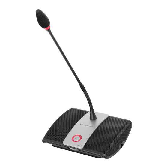
Overview of the components ADN C1 chairperson unit ³ · µ ¸ ¾ º ¶ » ² ´ ¿ ³ µ Sound inlet basket socket with firmly fixed windshield ¸ socket · Signal light ring » Headphone socket ¿ Priority key ´... -
Page 11: Adn Cu1 Central Unit
Overview of the components ADN CU1 central unit IN –– AUDIO –– OUT PORT II PORT I 100-240V~ 50/60Hz 240W 2x 52.8V 1.75A A Front view B Rear view On/off switch audio input Standard display key audio output Display panel PORT II socket (RJ 45) for connec- tion of conference units... - Page 12 Overview of the components Overview of the ADN CU1 display panel After switch-on, the central unit’s display shows progress bars (for the booting routine “Booting” and the self test “Selftest”) and then the standard display: Direct Access 30 Units Text/icon Possible display/function Conference mode Current conference mode:...
-
Page 13: Conference Manager" Software
Overview of the components “Conference Manager” software The “Conference Manager” software allows you to configure and control the entire conference from a Windows PC or directly from the ADN CU1 central unit. Information on the software can be found in the chapter “Using the “Conference Manager”... -
Page 14: Adn Ps Power Supply
Overview of the components ADN PS power supply ADN PS PORT I PORT II DATA CU/PS 100 - 240V 50/60Hz 385W PORT I & PORT II: max. 5.25A sum A Front view B Rear view Rack mount “ears” PORT I socket –... -
Page 15: The Sdc Cbl Rj-45 System Cables
Overview of the components The SDC CBL RJ-45 system cables The system cables transmit the digital audio and status information and supply power to the conference units. use unshielded Cat5 cable (26 AWG)! Shielded RJ 45 modular plug, Cat5(e) Gray cable booth with clip protector Round STP cable, cat 5(e), 24 AWG, black Black cable booth with clip protector 14 |... -
Page 16: Structuring And Controlling The Conference System
If cable lengths are shorter, it might be that more conference units can be used. ADN D1 delegate units and ADN C1 chairperson units can be combined in an arbi- trary order. The number of chairperson units, however, is limited to 10 max. per conference system. - Page 17 ADN CU1 central unit for controlling the conference. The conference units are inter- connected in two cable strings which are directly connected to the central unit. ADN CU1 max. 40 ADN D1/ADN C1 52.8 V >35 V 16 | ADN Digital Conference System...
- Page 18 The conference units are interconnected in cable strings and up to four cable strings can be connected to each ADN PS power supply. ADN CU1 ADN PS (max. 15) max. 70 ADN D1/ADN C1 52.8 V >35 V ADN Digital Conference System | 17...
- Page 19 ADN PS power supply. ADN CU1 ADN PS (max. 15) max. 40 ADN D1/ADN C1 52.8 V >35 V When connecting the conference units to an ADN PS power supply, you can...
-
Page 20: Calculating The Voltage Supply Of The Conference Units
Calculator” software allows you to calculate the voltage supply on the individual sections of a cable string or cable ring and to plan the structure of the conference system. The software is available from your Sennheiser partner or from the “Product Downloads” area on the product page at www.sennheiser.com. -
Page 21: Using The Adn Cable Calculator Software
Using the ADN Cable Calculator software Using the ADN Cable Calculator software “ADN Cable Calculator” software allows you to calculate the voltage supply on the individual sections of a cable string or cable ring and to plan the structure of the conference system. - Page 22 Using the ADN Cable Calculator software Click the “Next” button. A selection window for specifying the installation location appears: Use the default or select an installation path. Click the “Next” button. A summary of the selected installation settings is displayed: Confirm this summary by clicking the “Next”...
-
Page 23: Using The Adn Cable Calculator
Using the ADN Cable Calculator software Using the ADN Cable Calculator To use the “ADN Cable Calculator” software and to calculate the cable lengths and number of conference units: Start the “ADN Cable Calculator” software from the Start menu or the shortcut on your desktop. -
Page 24: Putting The Conference System Into Operation
Putting the conference system into operation Putting the conference system into operation Preparing the ADN CU1 central unit for use Setting up the central unit on a flat surface or mounting it into a rack If you want to place the central unit on a flat surface: Make sure that the air vents are not covered or blocked. - Page 25 Putting the conference system into operation Fastening the optional Unscrew and remove the 2 torx screws (T25) on each side of the central unit rack mount “ears” (see left-hand diagram). Secure the optional rack mount “ears” (see “Accessories” on page 154) to the sides of the central unit using the previously removed torx screws (see right-hand diagram).
-
Page 26: Preparing The Adn Ps Power Supply For Use
Putting the conference system into operation Preparing the ADN PS power supply for use If you want to place the ADN PS power supply on a flat surface: CAUTION Danger of material damage and personal injury due to stacked power supplies! When stacking several ADN PS power supplies on top of each other, •... - Page 27 Putting the conference system into operation If you want to mount the ADN PS power supply into a 19” rack: CAUTION Danger of material damage and personal injury when rack mounting the central unit! When installing the product in a closed or multi-rack assembly, please consider that, during operation, •...
-
Page 28: Preparing The Adn C1/Adn D1 Conference Units For Use
To ensure full operational reliability in a redundant ring topology, the hard- ware of the ADN C1 and ADN D1 has been revised. If you combine confer- ence units with hardware revision 1 (no marking on the type plate) and conference units with hardware revision 2 (“HW:... - Page 29 Putting the conference system into operation ¹ ¹ Insert the cable holder as shown. ¹ At this point, the cable holder not yet fixed with screws. You first have to connect the conference units as described in the chapter “Setting up the con- ference system”...
-
Page 30: Setting Up The Conference System
Plan the number of conference units required for your conference system. A total of 400 conference units can be used in a conference system (the number of ADN C1 chairperson units is limited to 10 max.). Always take the largest possible number of participants as a starting point. - Page 31 Repeat these steps for additional conference units. If necessary, repeat all steps for a second cable string. ADN CU1 ADN D1/ADN C1 IN –– AUDIO –– OUT PORT II PORT I 100-240V~ 50/60Hz 240W 2x 52.8V...
- Page 32 Putting the conference system into operation Connecting ADN PS power supplies to the ADN CU1 central unit For conference systems comprising more than 40 conference units or when the conference units are connected in a redundant ring topology, you require ADN PS power supplies.
- Page 33 Repeat these steps for additional conference units. If necessary, repeat all steps for a second, third and fourth cable string and additional ADN PS power supplies. ADN PS ADN D1/ADN C1 PORT I PORT II DATA CU/PS...
- Page 34 Putting the conference system into operation PORT I PORT I PORT II PORT II PORT I PORT I PORT II PORT II Please note that there is a limited number of approx. 15-20 conference units per cable string due to the voltage drop on the cable string (see page 15).
- Page 35 To ensure full operational reliability in a redundant ring topology, the hard- ware of the ADN C1 and ADN D1 has been revised. If you combine confer- ence units with hardware revision 1 (no marking on the type plate) and conference units with hardware revision 2 (“HW:...
- Page 36 Putting the conference system into operation ADN PS ADN D1/ADN C1 PORT I PORT II DATA CU/PS 100 - 240V 50/60Hz 385W PORT I & PORT II: max. 5.25A sum µ ¸ 6 7 8 9 PORT I PORT II...
- Page 37 Putting the conference system into operation Cabling errors If the cabling is wrong, the system may perhaps function, but operational reliability is compromised and monitoring cannot be carried out reliably. Therefore, avoid the following severe cabling errors: Ring topology connected to the A ring topology cannot be connected to the ADN CU1 ADN CU1 central unit central unit.
- Page 38 Putting the conference system into operation Conference units connected No conference units must be connected to the DATA to the DATA socket of the output socket of an ADN PS power supply. ADN PS power supply The error message “Error 60003 D1/C1 at PS casca- ding port”...
- Page 39 Putting the conference system into operation Ring topology connected to A ring topology cannot be connected different ADN PS power supplies to different PORT sockets of two dif- ferent ADN PS power supplies. The error message “Error 60006 Ring cabling between two PS”...
-
Page 40: Connecting External Audio Devices To The Central Unit
Putting the conference system into operation Connecting external audio devices to the central unit You can use different settings for processing the audio signals of the audio input and the audio output in order to avoid, for example, delayed or double audio signals in videoconferencing or teleconferencing systems (see page 58 or page 131). -
Page 41: Preparing To Use The "Conference Manager" Software
Putting the conference system into operation Connect the USB mass storage device to one of the two USB sockets If necessary, connect the mains unit of the USB mass storage device. Use a USB hub if the number of USB sockets is not sufficient or if the USB IN ––... -
Page 42: Switching The Conference System On/Off
Putting the conference system into operation Use a network cable (Cat5) to connect the Ethernet socket of the central unit to the network interface of your PC. You can also connect the PC and the central unit using a switch or similar. IN ––... -
Page 43: Using The Media Control System
Putting the conference system into operation Switching the conference system off If you have made changes to a configuration using the “Conference Man- ager” software, you have to save these changes before switching the central unit off (see page 103). All other settings of the central unit are automatically saved. - Page 44 PDF doc- ument “ADN_MediaCtrl_Protocol.pdf” included on the DVD-ROM (supplied with the central unit) or at www.sennheiser.com. For more questions on the integration of the ADN conference system into a media control system, contact your Sennheiser partner.
-
Page 45: Using The Central Unit
Using the central unit Using the central unit Deactivating the lock mode of the central unit If the lock mode is activated (see page 71), you have to deactivate it in order to be able to operate the central unit: Press the jog dial or any other key. -
Page 46: Configuring The Conference System Via The Central Unit
Configuring the conference system via the central unit Configuring the conference system via the central unit Overview of the operating menu “XLR Out” “Conference Menu” submenu submenu XLR Out Status Conference Mode XLR Out Volume Microphone Limit XLR Out Equalizer Request Limit Talk Time Status Talk Time Limit... - Page 47 Configuring the conference system via the central unit Display Function of the menu item Option/display Page “Main Menu” “Conference Menu” Calls up the “Conference Menu” submenu – “Audio Menu” Calls up the “Audio Menu” submenu – “System Menu” Calls up the “System Menu”...
- Page 48 Configuring the conference system via the central unit Display Function of the menu item Option/display Page “XLR Out” menu “XLR Out Status” Activates/deactivates the OUT audio output “On”/“Off” “XLR Out Volume” Adjusts the volume of the XLR output XLR Out Volume + 6 dB + 6 dB “01”...
- Page 49 Configuring the conference system via the central unit Display Function of the menu item Option/display Page “System Menu” “Units” Displays the type and number of the conference Units System : 216 D1 06 C1 units connected to the connections PORT of the : 00 D1 04 C1 ADN CU1 central unit or ADN PS power supplies...
-
Page 50: Working With The Operating Menu
Configuring the conference system via the central unit Working with the operating menu By way of example of the “Microphone Limit” menu item, this section describes how to use the operating menu. Information on the factory default settings of the operating menu can be found in the appendix (see page 158). -
Page 51: Adjusting The Conference Settings - "Conference Menu
Configuring the conference system via the central unit Canceling an entry Press the key. The operating menu or the next higher menu level appears. Press the standard display key. The standard display appears. To subsequently directly return to the last edited menu item: Press the jog dial repeatedly until the last edited menu item appears. - Page 52 Configuring the conference system via the central unit Situation The maximum number of speakers who can take the floor simul- taneously (“Microphone Limit”) has been reached. Event A further speaker presses the microphone key on his or her con- ference unit. Behavior “Direct Access”...
- Page 53 Please note that any connected ADN C1 chairperson unit is counted against the microphone limit (the number of chairperson units is limited to 10 max.). If you set a higher value (adjustment range “1”...
- Page 54 Configuring the conference system via the central unit The speaking time limit becomes effective only if it is activated in the “Talk Time Status” menu item (see previous section). Please note that the speaking time limit applies to each and every input to the discussion.
- Page 55 Setting the function of the priority key – “Clear Request List on Cancel” ¿ This menu item allows you to set the function of the priority key of the ADN C1 chairperson unit. Main Menu Clear Request List on Cancel...
-
Page 56: Adjusting The Audio Settings - "Audio Menu
Configuring the conference system via the central unit Adjusting the audio settings – “Audio Menu” “Audio Menu” submenu allows you to adjust settings that affect the audio signals of the conference system. Adjusting settings for the OUT audio output and the IN audio input – “XLR Out”... - Page 57 Configuring the conference system via the central unit Adjusting settings for the floor channel – “Floor/Loudspeakers” Main Menu Audio Menu Floor/Loudspeakers Conference Menu XLR Out Floor/Loudspeaker Volume Audio Menu XLR In Floor/Loudspeaker Equalizer System Menu Floor/Loudspeakers Select and call up the Select and call up the Select and call up “Audio Menu”...
- Page 58 Configuring the conference system via the central unit Situation The audio signal of the 1. conference unit is fed to the floor channel. Event The audio signal of another conference unit it fed to the floor channel. The volume level of the floor channel would increase if the signal wasn’t influenced.
- Page 59 Configuring the conference system via the central unit Possible settings: • “Off” : The function is deactivated. • “Low Intensity“: The volume can be slightly increased (approx. +2 to +3 dB); feedback is reduced. • “High Intensity“: The volume can be strongly increased (approx. +5 to +6 dB); feedback is reduced.
-
Page 60: Checking The System And Detecting Problems - "System Menu
Configuring the conference system via the central unit Submenu Menu item Function “Conference “Record“ Activates/deactivates the recording of the Recording“ conference on a USB mass storage device “Recording status“ Provides information on the status of the recording and on the available memory space on the USB mass storage device Conference Recording Record... - Page 61 Configuring the conference system via the central unit To ensure trouble-free operation of your conference system: Carry out the following steps before starting the conference. This allows you to diagnose and remedy errors in your conference system at an early stage. Set up your entire conference system.
- Page 62 Configuring the conference system via the central unit Display Only the structural change Direct Access 30 Units icon is displayed. Error Change in the number of conference units due to: • manual adding or removal of one or several conference units •...
- Page 63 Configuring the conference system via the central unit Display The warning triangle and the Direct Access 30 Units structural change icon displayed. Error and Change in the number of conference units during the self-test: remedy After switch-on, an automatic self-test is performed which simu- lates a running conference with all the conference units connected.
- Page 64 Configuring the conference system via the central unit Display Only possible if the conference Audio Distribution Network units are directly connected to Processing ... the ADN CU1 central unit: The warning triangle and the cable fault icon are displayed and the “Processing...” bar appears.
- Page 65 Configuring the conference system via the central unit Display Meaning Conference units are connected in a cable string to the PORT output Conference units are connected in a cable ring to the PORT output – – No conference units are connected to the PORT output System analysis –...
- Page 66 Configuring the conference system via the central unit Display Meaning and causes An undervoltage can be caused by • faulty conference units • too long system cables • too many conference units connected to a PORT socket The PORT socket is deactivated due to e.g. •...
- Page 67 Configuring the conference system via the central unit If the temperature is too high, proceed as follows: Make sure that the air vents of the ADN CU1 central unit and the ADN PS power supplies are not covered or blocked (see page 23 and page 25). If necessary, clean the air vents (see page 148).
- Page 68 Configuring the conference system via the central unit Performing a manual self-test – Start Self-Test Diagnostics Temperature Main Menu “Start Self-Test” System Menu Bus Statistics Diagnostics Start Self-Test Start Self-Test Select and call up the Select and call up the Select the desired “Diagnostics”...
- Page 69 To ensure full operational reliability in a redundant ring topology, the hardware of the ADN C1 and ADN D1 has been revised. If you combine conference units with hardware revision 1 (no marking on the type plate) and conference units with hardware revision 2 (“HW:...
-
Page 70: Adjusting The Language - "*Language
Always use consistent and up-to-date software revisions in order to be able to use all functions. Further information on software updates for your ADN conference system is available from your Sennheiser partner. Adjusting the language – “*Language” Via the “*Language” menu item, you can adjust the language of the operating... -
Page 71: Adjusting Further Settings - "Settings
Configuring the conference system via the central unit Adjusting further settings – “Settings” Adjusting network settings – “Network” submenu Main Menu Settings Network System Menu Network IP Adress Mode *Languages Contrast IP Address Settings Lock Subnet Mask Static IP Select and call up the Select and call up the Select and call up the “Settings”... - Page 72 Configuring the conference system via the central unit Setting the lock mode – “Lock” Main Menu Settings Lock System Menu Network *Languages Contrast Settings Lock Select and call up the Select and call up the Select the desired “Settings” submenu “Lock”...
-
Page 73: Running A Conference
Running a conference Running a conference The character of your conference (i.e. the conditions under which the participants can take the floor or are granted speaking privileges) depends on the settings of the central unit (see page 50). Possible settings: “Direct Access”, “Override”... -
Page 74: Operating A Delegate Unit
Running a conference Operating a delegate unit Taking the floor/Making a request to speak Depending on the conference mode set (see page 50), you can • take the floor immediately or • make a request to speak. You then have to wait until the chairperson activates your microphone. If the conference mode is set so that you can take the floor immediately (“Direct Access”... -
Page 75: Operating A Chairperson Unit
Running a conference Connecting headphones You can connect mono or stereo headphones to the conference unit to listen to the floor channel. The headphone volume can be individually adjusted on the confer- ence unit. » Connect headphones with a 3.5 mm jack plug to the headphone socket »... - Page 76 Running a conference Depending on the setting adjusted in the operating menu (see page 54): º · • the microphone LED flashes green and the signal light ring flashes red or º • only the microphone LED flashes green To grant speaking privileges to the next participant from the request-to-speak list: ´...
-
Page 77: Setting The Volume Of The Conference Units' Built-In Loudspeakers
Running a conference ¿ Keep the priority key pressed for as long as you want to mute the conference units. All conference units – except for the chairperson units – are muted immedi- · º · ately. The microphone LED and the signal light ring of the previously active conference units flash red. -
Page 78: Adding Conference Units To The Conference System During Operation
Running a conference The volume of the conference units’ loudspeakers can also be set via the central unit’s operating menu (see page 56) or the “Conference Manager” software (see page 130). Use the “Feedback Suppression” function to be able to increase the floor channel volume by up to 5 dB without feedback occurring (see page 57 or page 132). - Page 79 Running a conference Storage location The audio recordings are filed in the “ADN” folder on the USB mass storage device. For each recording of a conference, a new folder is created whose name consists of the name of the conference and the starting time (date and time). The name of the conference can be set via the “Conference Manager”...
- Page 80 Running a conference Monitoring an audio recording The CU1 display panel displays the status of the audio recording: Meaning Icon Direct Access 30 Units Audio recording in progress flashing Memory space < 500 MB Depending on the number of channels recorded, the memory capacity will suffice for approx.
-
Page 81: Using The "Conference Manager" Software
Using the “Conference Manager” software Using the “Conference Manager” software Possibilities of usage of the software and the conference system The “Conference Manager” software allows you to conveniently manage and control the conference system. With the software, you can plan and graphically simulate conferences. -
Page 82: Preparing The Central Unit's Integrated Software For Use
Using the “Conference Manager” software The following overview shows the functions that are available depending on the connections status: “Disconnected” – “Connected” – not connected to the connected to the ADN CU1 central unit ADN CU1 central unit “Setup” operating mode “Setup”... - Page 83 Using the “Conference Manager” software Installing the “Conference Manager” software The following steps describe the installation of the “Conference Manager” software on a PC running Windows XP. The installation on a PC running Windows Vista or Windows 7 is performed in a similar way. To install the software, you require administrator rights.
- Page 84 Using the “Conference Manager” software Confirm this summary by clicking the “Install” button. A confirmation prompt appears: Click the “Next” button. A selection window for specifying the installation location appears: Use the default or select an installation path. Click the “Next” button. A summary of the selected installation settings is displayed: ADN Digital Conference System | 83...
- Page 85 You can deinstall the “Conference Manager” software using the installation wizard on the DVD-ROM or using the Windows Control Panel (category “Add or Remove Programs”, entry “Sennheiser Conference Manager”). If you use the installation wizard to deinstall the software, the wizard automati- cally starts in repair mode: Start the “ADNSetup.exe”...
- Page 86 Using the “Conference Manager” software Ask your system administrator if a static IP address is to be used or if the IP address is to be allocated dynamically. If you have to use a static IP address, ask for the subnet mask and the standard gateway.
- Page 87 Using the “Conference Manager” software Windows XP Windows Vista Windows 7 Double-click “Local Area Connec- Double-click “Local Area Connec- Double-click “Local Area Connec- tion”. tion”. tion”. “Local Area Connection Status” “Local Area Connection Proper- window appears. ties” window appears. “Local Area Connection Status”...
-
Page 88: Starting/Exiting The Software
Using the “Conference Manager” software Windows XP Windows Vista Windows 7 b) The Windows PC is assigned a static IP address in the network. Settings to be adjusted via the central unit (see page 70): On the central unit, call up the “IP Mode”... - Page 89 Windows version of the software To start the software: Double-click the program icon on the desktop. Click “Start” > “All Programs” > “Sennheiser” > “ADN” > “SENNHEISER Conference Manager”. The “Conference Manager” software is started in “Setup” operating mode and the Room View window is displayed.
-
Page 90: Getting To Know And Adjusting The Basic Features Of The Software
Using the “Conference Manager” software Getting to know and adjusting the basic features of the software Overview of the software The main application window of the “Conference Manager” software consists of permanently visible elements and of views that depend on the operating mode. The following diagram shows the Windows version of the “Conference Manager”... - Page 91 Using the “Conference Manager” software Menu bar a Menu Submenu Function Page Global Menu New Conference Creates a new configuration Open Conference ... Loads an existing configuration 102 Delete Conference Deletes an existing configuration Close Closes the current configuration 104 Save Saves the current configuration (locally or on the central unit)
- Page 92 Using the “Conference Manager” software Menu Submenu Function Page Settings Conference Settings ... Opens the conference settings Audio Settings ... Opens the audio settings Conference Recording Opens the audio recording function Language Adjusts the language Set Password ... Sets the password protection Network Opens the network settings Re-init Conference...
- Page 93 Using the “Conference Manager” software Button Function Displays the connection status between the central unit and the “Conference Manager” software and/or a media control system (see page 100) “Device Disconnected“ “Device Connected“ Displays detected errors and opens the “Event Log” function (see page 143) Event log, no error messages are reported Error messages are reported...
- Page 94 Using the “Conference Manager” software Selecting operating modes and views In “Setup” and “Live” operating mode, you can switch between the Room View window and the Delegate View window. Views of the software depending on the operating mode “Setup” operating mode “Live”...
- Page 95 Using the “Conference Manager” software Selecting the Click the “Setup” button. “Setup” operating mode The software changes to “Setup” operating mode and the “Setup” button is highlighted in blue. To display the Room View window: Click the Room View button To display the Delegate View window: Click the Delegate View button 94 |...
- Page 96 Using the “Conference Manager” software Selecting the “Live” operating mode Prepare the “Live” operating mode and activate it (see page 133). To display the Room View window: Click the Room View button To display the Delegate View window: Click the Delegate View button ADN Digital Conference System | 95...
- Page 97 Using the “Conference Manager” software Adjusting the View windows to your needs You can adjust the Room View window and the Delegate View window to your needs. The library panels can be hidden or shown and can be changed in size. Changes to the View windows are not automatically saved and are reset to the factory default settings when the software is exited.
- Page 98 Using the “Conference Manager” software Adjusting the screen, mouse, and keyboard settings and the date/time setting of the central unit In the menu bar, click “Settings” > “System Properties”. “System Properties” window appears. To adjust the screen settings: Select the desired value from the drop-down list in the “Screen Resolution”...
- Page 99 Using the “Conference Manager” software Selecting the language In the menu bar, click “Settings” > “Language”. A list with the available languages appears. Click the desired language (Chinese, Danish, German, English, Finnish, French, Dutch, Italian, Japanese, Norwegian, Russian, Swedish, Spanish). The language of the software is changed.
- Page 100 Using the “Conference Manager” software In the menu bar, click “Settings” > “Network...”. “Network Settings” window appears. To automatically integrate the central unit into a network using a dynamic IP address: Select the “Obtain an IP Address automatically” option button. Click “OK”.
-
Page 101: Using The Conference System And The Software
Using the “Conference Manager” software Using the conference system and the software Connecting the software to the central unit To connect the “Conference Manager” software to the central unit: Start the software (see page 87). The “Open” window appears. Click the “Connect” button. In the menu bar, click “Global Menu”... - Page 102 Using the “Conference Manager” software Eliminating connection problems If no connection to the central unit can be established or if the configuration cannot be found, an error message appears. Check if the central unit is correctly connected (see page 81) and switched on (see page 41).
- Page 103 Using the “Conference Manager” software Loading a configuration In the menu bar, click “Global Menu” > “Open Conference”. The “Open” window appears. If the software is connected to a central unit (see page 100), you can load three types of configurations: Loading a configuration ...
- Page 104 Using the “Conference Manager” software Activating/deactivating automatic loading of a configuration To automatically load a saved configuration at startup of the conference system: In the menu bar, click “Global Menu” > “Autoload”. “Autoload Properties” window appears. Establish a connection to the central unit (see page 100). Select the “Enable Autoload”...
- Page 105 Using the “Conference Manager” software save newly created configuration on the hard disk of the Windows In the menu bar, click “Global Menu” > “Save”. “Save Conference” window appears. Select the “Save as Local Conference Document” option button. Click “OK”. “Save conference”...
- Page 106 Using the “Conference Manager” software Deleting a configuration from the central unit In the menu bar, click “Global Menu” > “Delete”. “Delete Conference” window appears. Select a configuration. Click “OK”. After a confirmation prompt, the selected file is deleted. The configuration of an active conference (marked with an asterisk “*”) and the default file name (“Default.adn”) cannot be deleted.
-
Page 107: Preparing A Conference And Mapping A Conference Room - "Setup" Operating Mode
Using the “Conference Manager” software Preparing a conference and mapping a conference room – “Setup” operating mode In “Setup” operating mode, you can use photos and graphical elements to map a conference room. Using delegate lists, you can clearly assign conference units to conference participants and then monitor and control your conference. Example of a photographical representation of the conference room (for how to use image files, see page 112): 106 | ADN Digital Conference System... - Page 108 Using the “Conference Manager” software Example of a graphical representation of the conference room (for how to place graphic objects on the canvas, see page 108): ADN Digital Conference System | 107...
- Page 109 Using the “Conference Manager” software Example of a delegate list (for how to create a delegate list, see page 118): Planning and mapping the conference room Placing objects on the canvas Click the Room View button 108 | ADN Digital Conference System...
- Page 110 Using the “Conference Manager” software Select an object from the “Equipment”, “Images” or “Microphone Unit(s)” library panels. The selected object is highlighted in blue. Drag the object onto the canvas. If the object can be dropped at the current cursor position, the object and the icon are displayed next to the mouse pointer.
- Page 111 Using the “Conference Manager” software Select the shape of the rectangles or circles from the “Proportion of Table” drop-down list. The thumbnail displays the selected shape. Click “OK”. The desired number of rectangles or circles is placed on the canvas. Newly placed objects can cover existing objects.
- Page 112 Using the “Conference Manager” software Defining fill, line and Please note when defining fill, line and border attributes: border attributes If you select an object in the library panel and then define fill, line and border attri- butes, the defined attributes apply to all newly created objects of this type. If you select an object already placed on the canvas and then define fill, line and...
- Page 113 Using the “Conference Manager” software To define the line color: Select the object. Click the “Color” button. Select a standard color. Click the button. “Select color” window appears. Select a color. Click “OK”. The line or border color is assigned to the selected object or to all newly created objects (see “Defining fill, line and border attributes”...
- Page 114 Using the “Conference Manager” software Click the Room View button To add an image file In the “Images” library panel, click “Import...“. The “Import...” window appears. Select an image file (file extension: “jpg”, “png” or “bmp”). Click “OK”. The selected image file is added to the library. If you save the configuration on the central unit (see page 103), all image files are copied and are then also available on the central unit.
- Page 115 Using the “Conference Manager” software Automatically aligning objects Hold down the “CTRL” key and select several objects on the canvas using the mouse. The objects appear with a bounding box (dotted line). The “Alignment” box appears. In the “Alignment” box, click one of the following buttons: Button Objects are aligned to the ...
- Page 116 Using the “Conference Manager” software Undoing/redoing actions Click the Room View button To reverse the last action you performed: Click the icon. To reverse the last “undo” action: Click the icon. You can undo and redo up to 10 actions. Copying/pasting/cutting objects To cut an object and paste it to the clipboard: Select the object that you want to cut and paste.
- Page 117 Using the “Conference Manager” software Moving objects forwards/backwards All objects on the canvas are placed on top of each other. To move an object backwards: Select an object. Click the icon. The selected object is moved backwards. To move an object forwards: Select an object.
- Page 118 Using the “Conference Manager” software Changing the size of the canvas Click the Room View button To enlarge/reduce the size of the canvas: Select the desired scaling factor from the “Size” drop-down list. The size of the canvas is adjusted. To rotate the contents of the canvas: Click The contents of the canvas are rotated by 90°.
- Page 119 Using the “Conference Manager” software To adjust the grid size: Enter the desired grid size (between 1 and 99) into the “Size” fields. The grid size is adjusted. To automatically align objects to the grid when you drop them on the canvas: Tick the “Snap”...
- Page 120 Using the “Conference Manager” software Click the “Add...” button. The “Delegate” window appears. To assign an already numbered and initialized conference unit to a delegate (only possible, if the conference units have been initialized, see page 122): Select the number of the conference unit you want to assign from the “Microphone ID”...
- Page 121 Using the “Conference Manager” software To change the line height of the text in the delegate list: Select the desired font size from the “Line height” drop-down list. To save a delegate to the delegate list with the settings made: Click “OK”.
- Page 122 Using the “Conference Manager” software If you want to change several delegate entries simultaneously to, for example, assign a specific color to a group of delegates: Hold down the “CTRL” key and select several delegates from the dele- gate list using the mouse. Right-click the selection.
-
Page 123: Initializing The Conference Units - "Setup" Operating Mode
Using the “Conference Manager” software Importing a delegate list* You can import a delegate lists from other configurations: CAUTION Loss of delegate data! If you import a delegate list, all existing delegate names will be deleted. This action cannot be reversed. Export the existing delegate list to save the data for later use (see above). - Page 124 Using the “Conference Manager” software Click the Room View button In the “Microphone Unit(s)” library panel, click the “Scan” button. The conference unit icons are placed on the canvas and initialized in the order which corresponds to the physical order of connection to the central unit. The sequential number of the conference units is displayed below the conference unit icons.
- Page 125 Using the “Conference Manager” software During initialization, you can extend or reduced the selection of conference unit icons: Select one or several conference unit icons using the mouse. Right-click the selection and confirm the confirmation prompt by clicking “OK”. The selected conference unit icons are included in or excluded from the initialization.
- Page 126 Using the “Conference Manager” software If you want to continue the initialization process: Click “Continue”. Changing the numbering of To change the numbering of the conference units: the conference units Click the “Resort” button. The “Resort” button becomes the “Stop Resort”...
-
Page 127: Adjusting The Conference Settings - "Setup" Operating Mode
Using the “Conference Manager” software Changing the orientation/visibility You can change the orientation/visibility of numbers and delegate names assigned of the icon labeling to the conference unit icons: Select a conference unit icon. The selected icon is marked with a blue rectangle and the “Label Orientation”... - Page 128 Please note that simultaneously any connected ADN C1 chairperson unit is counted against the microphone limit (the number of chairperson units is limited to 10 max.). If you set a higher value (adjustment range “1”...
- Page 129 Using the “Conference Manager” software Enter the max. number of speakers who can take the floor simultaneously into “Microphone Limit” field. Setting the maximum number of The setting adjusted in the “Request Limit” field becomes effective only if you are requests to speak using a chairperson unit (“Request”...
- Page 130 Using the “Conference Manager” software This setting affects your conference as follows (example): “Talk Time Limit” 15 (minutes) (speaking time limit) “Premonition Time Limit” 60 (seconds) (advance warning time) Effect 60 seconds before the speaking time limit expires, i.e. after 14 minutes in this example, the signal light ·...
- Page 131 Using the “Conference Manager” software Adjusting the audio settings Click the button on the toolbar. “Audio Settings” window appears. Setting the volume and the tone color CAUTION of the floor channel Danger of hearing damage due to loud hissing! When the floor channel volume is set to a high level or when several participants speak simultaneously, feedback (loud hissing noise) can occur.
- Page 132 Using the “Conference Manager” software Adjusting the processing of the The sum of the audio signals of all conference units is fed to the floor channel which conference units’ audio signals in turn is output via the conference units’ built-in loudspeakers and via the OUT in the floor channel audio output.
- Page 133 Using the “Conference Manager” software The conference units’ built-in loudspeakers only output audio signals that are fed in via the audio input (e.g. from a video- or teleconferencing system). Tick/untick the “Mic Loudspeaker Mute” check box. Contributions coming from the conference units’ microphones are not repro- duced via the conference units’...
-
Page 134: Controlling And Monitoring A Conference - "Live" Operating Mode
Using the “Conference Manager” software Controlling and monitoring a conference – “Live” operating mode In “Live” operating mode, you can: • control a conference from the screen, • use either the Room View window or the Delegate View window for controlling the conference, •... - Page 135 Using the “Conference Manager” software To open the Room View window in “Live” operating mode: Click the Room View button The Room View window appears: To open the Delegate View window in “Live” operating mode: Click the Delegate View button The Delegate View window appears: Using the software for controlling If you want to use the software for controlling a running conference:...
- Page 136 Using the “Conference Manager” software Monitoring a conference You can monitor a conference from the screen without intervening. Monitoring a conference using the Room View window Element Function/Meaning Permanent list of chairperson units, sorted by “ID” number Delegate units with speaking privileges, sorted by chronological order of registration Delegate units that have made a request to speak, sorted by chrono- logical order of registration...
- Page 137 Using the “Conference Manager” software Element Function/Meaning Permanent list of conference units, sorted by “ID” number, the name of the delegate (“Delegate”), the speaking privileges status (“Queue”) or the color assigned (“Color”). Settings made in “Setup” operating mode regarding the delegate list (see page 118) are also taken into account in “Live”...
- Page 138 Using the “Conference Manager” software Overview of the bar graphs The bar graphs display the current speaking privileges status of the conference units connected to the central unit. Bar graph Meaning Chairperson unit with speaking privileges Chairperson unit is deactivated Delegate unit with speaking privileges, 100% of the speaking time is available Delegate unit with speaking privileges,...
- Page 139 Using the “Conference Manager” software To arbitrarily grant speaking privileges to a conference unit that has made a request to speak (in “Request” and “Direct Access” mode): Click a green flashing conference unit icon. In the “Requests” box, click the conference unit to which you want to grant speaking privileges.
- Page 140 (see page 29). If necessary, re-initialize the conference unit icons (see page 122). If the type of conference unit (ADN C1 chairperson unit or ADN D1 delegate unit) assigned to the conference unit icon does not correspond to the connected hard- ware, the conference unit icon is marked with a yellow circle and an exclamation mark.
- Page 141 Using the “Conference Manager” software Setting the volume of the conference CAUTION units’ built-in loudspeakers Danger of hearing damage due to loud hissing! When the floor channel volume is set to a high level or when several participants speak simultaneously, feedback (loud hissing noise) can occur.
-
Page 142: Recording A Conference - "Conference Recording
Using the “Conference Manager” software To activate or deactivate the speaking time limit: In the “Talk Time” box, tick/untick the “Limitation” check box (see also page 128): – ticked : The speaking time limit is activated. – unticked : The speaking time limit is deactivated. To change the speaking time limit: In the “Talk... - Page 143 Using the “Conference Manager” software Starting the recording Make sure that the USB mass storage device is correctly connected to the ADN CU1 central unit (see page 39). In the menu bar, click “Settings” > “Conference Recording”. “Conference Recording” window appears. Click “Record”.
-
Page 144: Using The Log And Diagnosis Function - "Event Log
Using the “Conference Manager” software Using the log and diagnosis function – “Event Log” The log and diagnosis function allows you to log all changes to the conference system. During normal operation, the button is displayed on the toolbar. As soon as a change to the system or an error is detected, the button on the toolbar changes to... - Page 145 [DU / PU] / Hardware versions of the [CUSB] ADN D1 chairperson unit VARIOUS (“DU”) or ADN C1 delegate unit (“PU”) or the ADN CU1 central unit (“CUSB”); are different (“VARIOUS”) HW Version #/ [Power Supplies] Hardware version of the ADN PS power supply;...
- Page 146 CU recording performance [CU Main Performance problem of the problem ######] CU1. In case of repeated occur- rence, contact your Sennheiser partner (see page 153. Insufficient USB device [CU Main Read/write speed of the USB performance ######] mass storage device is not...
- Page 147 Using the “Conference Manager” software Column “Description“ “Location“ Meaning Set Floor Mix=## [CU Main Automatic volume reduction ######] could not be changed because denied => Value out of the value is out of the permis- range(##..##) sible range Set Floor Volume=## [CU Main Volume of the floor channel ######]...
- Page 148 Using the “Conference Manager” software Column “Description“ “Location“ Meaning Unknown Conference [CU Main Unknown status of the audio Recording Status (##) ######] recording USB device full [CU Main Memory space on the USB mass ######] storage device is full “Critical Error“ Column “Description“...
-
Page 149: Cleaning And Maintaining The Conference System
Cleaning and maintaining the conference system Cleaning and maintaining the conference system CAUTION Liquids can damage the product! Liquids entering the product can cause a short-circuit in the electronics or damage the mechanics. Solvents or cleansing agents can damage the surfaces of the product. Keep all liquids away from the product. -
Page 150: Updating The Firmware Of The Conference System
“ADN System Software Setup” manual included on the DVD-ROM (supplied with the central unit) or at www.sennheiser.com. For further information on firmware updates for your ADN conference system, contact your Sennheiser partner. ADN Digital Conference System... -
Page 151: If A Problem Occurs
The maximum number of requests to Increase the maximum number of 52 or 128 speak has been reached. requests to speak. The ADN C1 chairperson unit has not If chairperson units are connected 54 or 124 been initialized before use. afterwards, you have to initialize them. - Page 152 Use an ADN C1 chairperson unit to (e.g. “Request”). grant speaking privileges. Use the “Conference Manager” soft- ware to grant speaking privileges.
- Page 153 Error number Possible cause Possible solution Unlisted error number System error Contact your Sennheiser partner (see page 153). 60002 Faulty system cable Replace the faulty system cable and switch the con- ference system on again (see page 41). Conference units with hardware revi-...
- Page 154 If a problem occurs that is not listed in the above table or if the problem cannot be solved with the proposed solutions, please contact your local Sennheiser partner for assistance. To find a Sennheiser partner in your country, search at www.sennheiser.com under “Service & Support”. ADN Digital Conference System...
-
Page 155: Accessories
ADN CU1 central unit Conference units Cat. No. Product name and description 502758 ADN D1 delegate unit 502759 ADN C1 chairperson unit 504001 ADN TR 1 cable holder for conference unit System cables Cat. No. Product name and description 009842... -
Page 156: Specifications
Specifications Specifications ADN D1 and ADN C1 conference units Dimensions (w/o gooseneck) 185 x 63 x 140 mm (W x H x D) Weight approx. 700 g Supply voltage 35 V ... 52.8 V Power consumption 2 W (w/o reproduction via loudspeakers) Temperature range operation: +10°C to +40°C... - Page 157 Specifications XLR OUT < 100 Ω Output resistance 20 Hz to 14.5 kHz; −3 dB Frequency response Output level max. +11 dBu Nominal level +6 dBu DHT (at 1 kHz) < 0.02% A-weighted at +7.5 dBu Signal-to-noise ratio > 80 dB A-weighted at +11 dBu ADN PS power supply Dimensions 482.5 x 168 x 100 mm (W x L x D)
-
Page 158: Appendix
Appendix Appendix ADN CU1 mounting dimensions ADN Digital Conference System | 157... - Page 159 Appendix ADN PS mounting dimensions Factory default settings Menu item/description Factory default settings “Conference Mode” – conference mode “Direct Access” “Microphone Limit” – max. number of speakers “4” who can take the floor simultaneously “Request Limit” – max. number of requests to “10”...
- Page 160 Appendix Menu item/description Factory default settings “XLR IN Equalizer” – tone color of audio input 0 dB “Floor/Loudspeakers Volume” – floor channel “16” volume “Floor/Loudspeakers Equalizer” – tone color of 0 dB floor channel “Audio Gain Reduction” – processing of the volume no reduction level of the floor channel (“0.0 dB per...
- Page 161 You may use the software on the device with which you acquired the software. Additional Licensing Requirements and/or Use Rights. a. Specific Use. Sennheiser designed this device for a specific use. You may only use the software for that use.
- Page 162 • Remote Boot Feature. If the Sennheiser enabled the device Remote Boot feature of the software, you (i) use the Remote Boot Installation Service (RBIS) tool only to install one copy of the software on your server and to deploy the software on licensed devices as part of the Remote Boot process;...
- Page 163 Authenticity label with a genuine copy of the software identifies licensed software. To be valid, this label must be affixed to the device, or included on or in Sennheiser's software packaging. If you receive the label separately, it is not valid. You should keep the label on the device or packaging to prove that you are licensed to use the software.
-
Page 164: Manufacturer Declarations
Manufacturer Declarations Manufacturer Declarations Warranty Sennheiser electronic GmbH & Co. KG gives a warranty of 24 months on this product. For the current warranty conditions, please visit our website at www.sennheiser.com or contact your Sennheiser partner. In compliance with the following requirements •... -
Page 165: Index
Chairperson unit Adding activating the microphone 73 conference units 77 configuring the priority key 54 ADN C1, Chairperson unit connecting to the central unit 30, 32, 34 ADN Cable Calculator 20 deactivating the microphone 73, 137 deinstallling the software 22... - Page 166 Index enlarging the canvas 116 Configuring establishing a connection between software and confe- via central unit 45 rence system 80 via software 126 full screen mode 96 Connecting functionality 19 Conference Manager software to the central unit 80, 100 getting to know and adjusting basic features 89 conference units to the central unit 30, 32, 34 hardware platform 80 Windows PC to central unit 40...
- Page 167 Index adjusting the volume 56, 130 Overview operating menu of the central unit 45 Floor/Loudspeakers 56, 130 Further settings 70 connecting to the central unit 40 Headphones system requirements 81 connecting 74 Planning and simulating conferences 80 setting the headphone volume 74 Port I and II connected topologies 63 number and type of connected conference units 63...
- Page 168 Index Start Self-Test 67 Structuring conference system 15 Switching on/off conference system 41 System analysis 64 System bus errors displaying 66 System cables 14, 154 calculating the cable lengths 22 connecting to the central unit 30, 32, 34 System Load 64 Talk Time Limit 52, 128 Temperature status displaying 65...
- Page 169 Printed in Germany Publ. 09/11 546401/A01 Sennheiser electronic GmbH & Co. KG Am Labor 1, 30900 Wedemark, Germany www.sennheiser.com...
Need help?
Do you have a question about the ADN C1 and is the answer not in the manual?
Questions and answers