Sennheiser TeamConnect Instruction Manual
Meeting and audio conference solution
Hide thumbs
Also See for TeamConnect:
- User manual (28 pages) ,
- User manual (33 pages) ,
- User manual (32 pages)
Table of Contents
Advertisement
Quick Links
Download this manual
See also:
User Manual
Advertisement
Table of Contents

Related Manuals for Sennheiser TeamConnect


Summary of Contents for Sennheiser TeamConnect
- Page 1 TeamConnect Meeting and audio conference solution Instruction Manual...
- Page 2 TeamConnect...
-
Page 3: Table Of Contents
Installing the SL TeamConnect CU1............... 22 Establishing a network connection ............... 23 Connecting the SL TeamConnect CU1 to the telephone landline network ..25 Connecting the SL TeamConnect CB1 to the SL TeamConnect CU1 ....26 Installing the SL TeamConnect CB1 in a meeting room ........26 Using the GPIO port of the SL TeamConnect CB1 .......... - Page 4 Contents TeamConnect...
-
Page 5: Important Safety Instructions
19. The power supply must be readily accessible so that the equipment can be easily disconnected from the AC power. 20. Do not attempt to service the power supply yourself, as opening or removing covers may expose you to dangerous voltage, and will void the limited warranty. TeamConnect... - Page 6 Danger of hearing damage due to high volumes This product is used for commercial purposes. Commercial use is subject to the rules and regulations of the trade association responsible. Sennheiser, as the manufacturer, is therefore obliged to expressly point out possible health risks arising from use.
-
Page 7: Package Contents
A list of accessories can be found on the TeamConnect product page at www.sennheiser.com. For information on suppliers, contact your local Sennheiser partner: www.sennheiser.com > “Service & Support” This instruction manual is divided into two parts: • The first part gives a general overview of the TeamConnect system, introducing... -
Page 8: System Introduction
System Introduction The Sennheiser TeamConnect solution The Sennheiser Group, with its headquarters in Germany, is one of the world‘s leading manufacturers of microphones, headphones and wireless transmission systems. We are shaping today the audio world of tomorrow – that is the ambition that we and our company live by from day to day. -
Page 9: Using The Teamconnect System
For web conferencing you need a computer with a web conferencing software (e.g. WebEx, Skype, etc.) which you connect via USB to the TeamConnect Combox in the meeting room. The Combox is the audio interface which is required to process the audio signals of the web conference in the TeamConnect system. -
Page 10: Using The Teamconnect System For Teleconferencing
For teleconferences the TeamConnect system is used to establish the telephone connection and to process all audio signals of the teleconference. The mobile dialer iOS App or the browser-based dialer are used to operate the TeamConnect system. You can use the dialer to dial the desired telephone number and to control all audio signals of the teleconference. - Page 11 Select the desired meeting room in the “TeamConnect” App. Log in using the room password provided by the system administrator. Dial a telephone number or select a number from the TeamConnect Phonebook or the Address Book of your iPad / iPhone to start the teleconference.
- Page 12 Using the TeamConnect system browser-based dialer on computer To start a teleconference with the browser-based dialer: Connect your computer via WLAN or LAN to the desired network. Open a web browser on your computer. Enter the address of the meeting room in the address bar of the browser. The address is provided by the system administrator.
- Page 13 Using the TeamConnect system Enter the room password provided by the system administrator. Dial a telephone number or select a number from the TeamConnect Phonebook to start the teleconference. TeamConnect | 13...
-
Page 14: Using The Teamconnect System For Web Conferencing
(e.g. WebEx, Skype, etc.) installed on a computer. The computer with the web conferencing software is connected to the TeamConnect system via the TeamConnect Combox in the meeting room, which is the audio interface for connecting the computer to the TeamConnect system. -
Page 15: Using The Teamconnect System For Conferencing Applications With Mobile Phones Or Tablet Pcs
Article number: 005362 GSM-ADP-CBB01 EasyDisconnect to 3.5 mm jack plug adapter Article number: 502729 To connect your mobile phone or your tablet PC to the TeamConnect Combox: Connect the RJ-9 connector of the EasyDisconnect adapter to the socket of the TeamConnect Combox. -
Page 16: The Teamconnect Components
8 audio output channels. The network and telephone landline connections are also established by the Central Unit. For using the TeamConnect system you do not need to operate the Central Unit directly. The system is operated via your own device (e.g. tablet, smartphone or computer). -
Page 17: Speechline Microphones And Microphone Accessories
SpeechLine microphone series. SpeechLine active loudspeakers The Sennheiser SL Loudspeaker 52 A is part of the SpeechLine product family and is compatible with the TeamConnect solution. It has been developed to provide the best possible audio experience and speech intelligibility in meeting environments. -
Page 18: Configuration Manager Software
The TeamConnect components Configuration Manager software The Configuration Manager software is used by the system administrator to set up and configure all components used with the TeamConnect system. It is not used for operating the TeamConnect system for teleconferencing and web conferencing. -
Page 19: Installation Guide
TeamConnect solution. The following illustration provides a schematic overview of the components and connections of the TeamConnect system. The components highlighted in orange must be accessible for the user in the meeting room. The components highlighted in blue form the system infrastructure. -
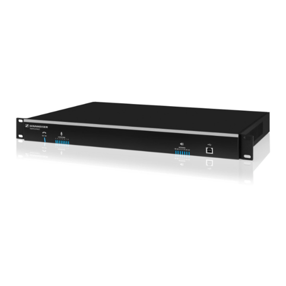
Page 20: Sl Teamconnect Cu1 - Product Overview
Installing and connecting the TeamConnect components SL TeamConnect CU1 - Product overview Front 1 ON / OFF hook indicator Indicates if the telephone line is active (blue) or inactive (red) Indicate which microphone channels are active (blue) or muted (red) -
Page 21: Sl Teamconnect Cb1 - Product Overview
Installing and connecting the TeamConnect components SL TeamConnect CB1 - Product overview Front TeamConnect C POWER indicator Back GPIO port for connecting external switches or status indicators D CONTROL / STATUS logic port For information on the pin allocation refer to page 27. -
Page 22: Installing The Sl Teamconnect Cu1
Installing the SL TeamConnect CU1 All components of the TeamConnect system used in the meeting room setup must be connected to the central control unit SL TeamConnect CU1. When all cables are connected, the SL TeamConnect CU1 can be installed permanently. The user does not need to access the SL TeamConnect CU1 directly. -
Page 23: Establishing A Network Connection
Installing and connecting the TeamConnect components Establishing a network connection You can either connect the SL TeamConnect CU1 to an existing network or you can set up a separate wireless network for directly accessing the SL TeamConnect CU1 in telephone or web conferences. After establishing a network connection the mobile dialer iOS App “TeamConnect”... - Page 24 Installing and connecting the TeamConnect components Setting up a separate wireless network For exclusive access to the SL TeamConnect CU1 you can set up a separate wireless network. To connect the SL TeamConnect CU1 to a WLAN router: LAN4 LAN3...
-
Page 25: Connecting The Sl Teamconnect Cu1 To The Telephone Landline Network
For teleconferencing the SL TeamConnect CU1 is needed to establish the telephone connection. It must be connected to the analog telephone landline network. The SL TeamConnect CU1 also offers the possibility of connecting an analog telephone set. Connecting the SL TeamConnect CU1 to an analog phone line... -
Page 26: Connecting The Sl Teamconnect Cb1 To The Sl Teamconnect Cu1
Installing the SL TeamConnect CB1 in a meeting room The SL TeamConnect CB1 must be installed in the meeting room in such a way that the user has easy access to it in order to connect their computer. -
Page 27: Using The Gpio Port Of The Sl Teamconnect Cb1
Some of the Sennheiser SpeechLine microphones also have logic ports which can be connected to the GPIO port of the SL TeamConnect CB1. This enables the control of the master mute function and the indication of the mute status directly at the microphones. -
Page 28: Connecting A Computer
For web conferencing applications the user can use the TeamConnect system to process the audio signals of the web conference. For that purpose the computer must be connected to the SL TeamConnect CB1, which is installed in the meeting room. -
Page 29: Connecting The Sl Teamconnect Cu1 To A Media Control System
TeamConnect Media Control Protocol You will find the list of commands required for using the SL TeamConnect CU1 with a media control system in the TeamConnect Media Control Protocol document “TeamConnect_Media_Control_Protocol.pdf” on the TeamConnect product page at www.sennheiser.com. -
Page 30: Connecting Microphones
You can connect up to eight microphones to the orange MIC / LINE IN terminal of the SL TeamConnect CU1. For attaching the microphone cables you need the supplied terminal connectors. To connect a microphone to the SL TeamConnect CU1: Remove the insulation from the wires at the end of the microphone cable. -
Page 31: Connecting Audio Output Signals
(e.g. active loudspeakers or other audio devices). To connect an audio output signal to the SL TeamConnect CU1: Remove the insulation from the wires at the end of the audio cable. Attach the three wires to the terminal connector observing the correct pin allocation (see figure on the left). -
Page 32: Preparing The Quick Guide And The Room Sticker For The User
The Room Sticker should only be used if the user already knows how the TeamConnect system works. If the user does not know how the TeamConnect system works, the Quick Guide is useful to help them get started with the system. -
Page 33: The Configuration Manager Software
In order to configure the TeamConnect system with the Configuration Manager software, you have to connect the computer, on which the Configuration Manager software is installed, to the SL TeamConnect CU1. There are three possibilities to connect the computer to the SL TeamConnect CU1: • via the... - Page 34 Type A The SL TeamConnect CU1 is detected as a USB device on your computer and the USB driver is installed. The SL TeamConnect CU1 is available in the Configuration Manager software. Connecting the computer to the SL TeamConnect CU1 via a serial cable...
-
Page 35: Navigating The Configuration Manager Software
SL TeamConnect CU1 devices available in the network or subnetwork. In the icon of each SL TeamConnect CU1 in the Connections list you can see the type of connection indicated with a symbol of the respective plug (USB, RS-232 or Ethernet). - Page 36 The status indicators on the bottom of the window indicate the following information. Status Indicator Status Communications Indicates if an SL TeamConnect CU1 is connected via USB, RS-232 or Ethernet or not connected. Telephone In Use Indicates if the telephone line is in use. Mic / Mute Gating Indicates if a microphone channel is muted or gated.
- Page 37 Applies the stored Preset 4 Tools menu Option Settings Network Find Opens a search dialog to find an SL TeamConnect CU1 device in the network via the network name or the IP address. Phonebook Edit Opens the Phonebook of the SL TeamConnect CU1. The telephone numbers stored in the Phonebook can be accessed in the mobile dialer and the browser-based dialer.
-
Page 38: Configuring The Sl Teamconnect Cu1
SL TeamConnect CU1. To open the configuration screen of an SL TeamConnect CU1: Click on the icon of the desired SL TeamConnect CU1 in the Connections list. The configuration screen of the selected SL TeamConnect CU1 opens. -
Page 39: Configuring Microphone Settings
Configuring microphone settings The audio settings of microphones and audio devices connected to the orange MIC / LINE IN terminal of the SL TeamConnect CU1 are configured in the Mics area of the configuration screen. To configure the microphone settings: Click on the Mics icon in the configuration screen. - Page 40 Shows the difference of the loss through the echo Return Loss cancellation and the non-linear processing chain Enhancement (ERLE) Total Echo Shows the total ERL and ERLE reduction. Open the respective tab to adjust the desired settings. 40 | TeamConnect...
-
Page 41: Configuring Audio Processing Settings
To apply the settings of the audio processing channels to input and output channels: Open the Mixer Console (see page 51). Route the processing channels to the desired audio channels. Close the Mixer Console. The audio processing settings are applied to the selected channels. TeamConnect | 41... -
Page 42: Configuring Line Input Settings
The audio settings of audio devices connected to the green LINE IN terminal of the SL TeamConnect CU1 are configured in the Inputs area of the configuration screen. To configure the line input settings: Click on the Inputs icon in the configuration screen. -
Page 43: Configuring Audio Output Settings
The audio settings of the audio output channels of the black LINE OUT terminal of the SL TeamConnect CU1 are configured in the Outputs area of the configuration screen. To configure the audio output settings: Click on the Outputs icon in the configuration screen. -
Page 44: Configuring Teleconference Settings
The Configuration Manager software Configuring teleconference settings The teleconference settings of the TeamConnect system are configured in the Telco area of the configuration screen. To configure the teleconference settings: Click on the Telco icon in the configuration screen. The Telephone Settings configuration window opens. - Page 45 Dialer Country Setting Selects the region you are using the TeamConnect system in. If the SL TeamConnect CU1 is connected to the analog landline network: Select your region If the SL TeamConnect CU1 is connected to a PBX telephone system: Select the region “US/Canada”...
-
Page 46: Configuring The Settings Of The Sl Teamconnect Cb1
The Configuration Manager software Configuring the settings of the SL TeamConnect CB1 The settings of the USB and Headset ports of the SL TeamConnect CB1 are configured in the COM Settings area of the configuration screen. To configure the settings of the SL TeamConnect CB1: Click on the COM Settings icon in the configuration screen. -
Page 47: Configuring Communication Settings
The Configuration Manager software Configuring communication settings The settings of the network and serial connections of the SL TeamConnect CU1 are configured in the Communications area of the configuration screen. To configure the communication settings: Click on the Communications icon in the configuration screen. -
Page 48: Using The Device Toolbox
Sennheiser microphones. You can use the listed devices to apply their audio setting presets to an audio channel of the SL TeamConnect CU1. You can also edit the existing devices or create new audio setting presets for common audio devices. - Page 49 The manufacturer name and model will be displayed as Make and Model in the input and ouput channel configuration windows. Configure the desired audio settings. Click OK to save the audio settings as a device in the Device Toolbox. TeamConnect | 49...
- Page 50 Open the Device Toolbox Editor. Select the desired device in the list of existing devices. Click Delete. The selected device is deleted from the Device Toolbox. The audio setting presets of the Sennheiser microphones and loudspeakers cannot be deleted. 50 | TeamConnect...
-
Page 51: Using The Mixer Console
To adjust the level of an input-output cross point: Right-click on the orange or green cell of the input-output cross point. Select Cross Point from the shortcut menu. Move the slider to adjust the level to the desired value. TeamConnect | 51... - Page 52 Open the Mic Settings configuration window (see page 39). Navigate to the Processing tab. Select Virtual Ref 1 or Virtual Ref 2 in the AEC/PA Reference 1 or AEC/PA Reference 2 dropdown menu. The selected virtual reference channel is used as reference for echo cancellation. 52 | TeamConnect...
-
Page 53: Using Presets
Configuration Manager software can be saved as presets for later use. There are four preset slots for saving the settings. The presets are stored directly on the SL TeamConnect CU1. They can be applied later by the user with the dialer. If you save the configuration settings as a configuration settings file (.CU1) on your computer using the... -
Page 54: Cleaning And Maintaining The Teamconnect Components
Cleaning and maintaining the TeamConnect components Cleaning and maintaining the TeamConnect components CAUTION Damage to the product caused by liquids! Liquids entering the product can short-circuit the electronics or damage the mechanics. Solvents or cleansing agents can damage the surface of the product. -
Page 55: Specifications
Specifications Specifications SL TeamConnect CU1 Housing Dimensions (W x H x D) 17" x 7.5" x 2" (43.2 cm x 19.1 cm x 5.1 cm) Weight 4.5 lbs. (2.25 kg) Audio performance Conditions Unless otherwise specified, all measurements are performed with a... - Page 56 Operation: 0 to +40 °C Storage: -30 to +85 °C Relative air humidity 20 to 90 % SL TeamConnect CB1 Housing Dimensions (W x H x D) 4.7" x 5.6" x 1.7" (11.9 cm x 14.3 cm x 4.4 cm) Weight 1.51 lbs.
- Page 57 FCC CFR 47 Part 15b + 68 ICES 003 + CS03 UL/CSA 60950-1 WARNING This is a Class A product. In a domestic environment this product may cause radio interference in which case the user may be required to take adequate measures. TeamConnect | 57...
-
Page 58: Manufacturer Declarations
Manufacturer Declarations Manufacturer Declarations Warranty Sennheiser electronic GmbH & Co. KG gives a warranty of 24 months on this product. For the current warranty conditions, please visit our website at www.sennheiser.com or contact your Sennheiser partner. CU1 and CB1 In compliance with the following requirements • Battery Directive (2006/66/EC) - Page 59 The country code must be set correctly in Console to ensure that the unit operates properly when connected to the Telco network, and that it complies with the country’s Telco requirements. Changing this code to a country other than the intended country of operation might cause TeamConnect devices to be non- compliant. 304. TeamConnect...
- Page 60 No user serviceable parts are contained in this product. If damage or malfunction occurs, contact Sennheiser Electronic Corp for instructions on its repair or return. Connection to party line service is subject to state tariffs. Contact the state public utility commission, public service commission or corporation commission for information.
- Page 61 TeamConnect | 61...
- Page 62 Sennheiser electronic GmbH & Co. KG Am Labor 1, 30900 Wedemark, Germany www.sennheiser.com Publ. 05/14, 554608/A02...
Need help?
Do you have a question about the TeamConnect and is the answer not in the manual?
Questions and answers