Cisco TelePresence MX800 Single Installation Manual
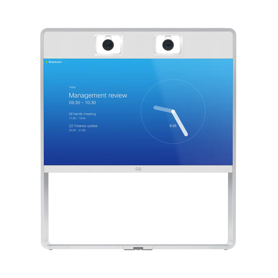
Wall-mounted mx800 single
Hide thumbs
Also See for TelePresence MX800 Single:
- Replacement manual (47 pages) ,
- Installation manual (30 pages) ,
- Spare parts (24 pages)

Related Manuals for Cisco TelePresence MX800 Single


Summary of Contents for Cisco TelePresence MX800 Single
-
Page 1: Installation Guide
Installation guide for Cisco TelePresence MX800 Single mounted on the wall 78-100255-02A0 | AUGUST 2015 | © 2015 Cisco Systems, Inc. All rights reserved. http://www.cisco.com/go/mx-docs... -
Page 2: User Documentation
The instructions in this guide apply to systems with single and dual including compliance and safety information, camera, even if the illustrations show only the single camera option. can be found on the Cisco website, http://www.cisco.com/go/mx-docs 78-100255-02A0 | AUGUST 2015 | © 2015 Cisco Systems, Inc. All rights reserved. Page 2... - Page 3 WARNING: This is a class A product. In a domestic environment this product may cause radio interference in which case the user may be required to take adequate measures. 78-100255-02A0 | AUGUST 2015 | © 2015 Cisco Systems, Inc. All rights reserved. Page 3...
-
Page 4: Safety Information
The wall-mounted system must be installed by qualified personnel, in accordance with state and local building regulations. Manpower We recommend four people working together to mount this system. Follow local regulations. 78-100255-02A0 | AUGUST 2015 | © 2015 Cisco Systems, Inc. All rights reserved. Page 4... - Page 5 - The camera will give an elevated view of the room. This view is not optimal for video conferencing. Further information: http://www.cisco.com/go/projectworkplace 2D CAD drawings with measurements: http://www.cisco.com/go/mx-docs (Technical References) 78-100255-02A0 | AUGUST 2015 | © 2015 Cisco Systems, Inc. All rights reserved. Page 5...
- Page 6 (screws and mounting hardware not provided; not shown in illustration). 78-100255-02A0 | AUGUST 2015 | © 2015 Cisco Systems, Inc. All rights reserved. Page 6...
- Page 7 A, B Place the lower frame onto the wall bracket. Fasten the lower frame to the wall bracket with two screws. 2 × M6x12, pan 78-100255-02A0 | AUGUST 2015 | © 2015 Cisco Systems, Inc. All rights reserved. Page 7...
- Page 8 Push the support bracket Tighten the screws and tight against the back plate check that the clamp is of the monitor. properly fastened. 78-100255-02A0 | AUGUST 2015 | © 2015 Cisco Systems, Inc. All rights reserved. Page 8...
- Page 9 78-100255-02A0 | AUGUST 2015 | © 2015 Cisco Systems, Inc. All rights reserved. Page 9...
- Page 10 Do not let go of the monitor before it is Front view securely placed on the lower frame. 78-100255-02A0 | AUGUST 2015 | © 2015 Cisco Systems, Inc. All rights reserved. Page 10...
- Page 11 Place the cover on the lower frame. 2 × Bracket Left side of the Right side of the monitor, viewed monitor, viewed from underneath from underneath 78-100255-02A0 | AUGUST 2015 | © 2015 Cisco Systems, Inc. All rights reserved. Page 11...
-
Page 12: Connect Cables
CAT 5e, shielded Ethernet cable, 5 m. extension cord, and country-specific cable Two presentation cables are provided: HDMI ↔ HDMI; and DVI/Euroblock ↔ VGA/mini jack. 78-100255-02A0 | AUGUST 2015 | © 2015 Cisco Systems, Inc. All rights reserved. Page 12... - Page 13 The Ethernet socket is behind the lid at the rear of Touch 10. Use one of the provided PoE rated CAT 5e Ethernet cables, 12.5 or 4 m, flat. 78-100255-02A0 | AUGUST 2015 | © 2015 Cisco Systems, Inc. All rights reserved. Page 13...
-
Page 14: Start Up The System
If your system is not set up to be automatically provisioned, configure the system before you make your first call. Initial configuration is described in the Getting Started Guide on the Cisco website. 78-100255-02A0 | AUGUST 2015 | © 2015 Cisco Systems, Inc. All rights reserved. Page 14... - Page 15 Installation guide for Cisco TelePresence MX800 Single - Wall mount Mount covers and textile grilles F, H Use the provided gloves when handling the textile grille. The grilles and side covers snap to magnets. 78-100255-02A0 | AUGUST 2015 | © 2015 Cisco Systems, Inc. All rights reserved. Page 15...
- Page 16 Cisco and the Cisco logo are trademarks or registered trademarks of Cisco and/or its affiliates in the U.S. and other countries. To view a list of Cisco trademarks, go to this URL: www.cisco.com/go/trademarks. Third-party trademarks mentioned are the property of their respective owners. The use of the word partner does not imply a partnership relationship between Cisco and any other company.
Need help?
Do you have a question about the TelePresence MX800 Single and is the answer not in the manual?
Questions and answers