Bosch MIC550 User Manual
Hide thumbs
Also See for MIC550:
- User manual (66 pages) ,
- Installation and user manual (54 pages) ,
- Installation manual (9 pages)
Table of Contents
Advertisement
Advertisement
Table of Contents

Related Manuals for Bosch MIC550


Summary of Contents for Bosch MIC550
- Page 1 MIC Series 550 MIC550...
- Page 2 Operation Manual...
-
Page 3: Table Of Contents
12.3 Controlling the Camera 12.3.1 Basic Keyboard Operation 12.3.2 Navigating the On-Screen Display (OSD) Menus 12.3.3 Keyboard Commands, Bosch Protocol 12.3.4 Keyboard Commands, Pelco Protocol 12.3.5 Special Preset Commands, Pelco Protocol 12.4 About Setting the Camera Address via FastAddress 12.5 FastAddress, Bosch Protocol 12.6... - Page 4 | Table of Contents MIC Series 550 12.7.2 Setting Passwords, Bosch Protocol On-Screen Display (OSD) Menus (Bosch Protocol) 13.1 Camera Setup Menu 13.2 Lens Setup Menu 13.3 PTZ Setup Menu 13.4 Display Setup Menu 13.5 Communication Setup Menu 13.6 Alarm Setup 13.7...
-
Page 5: Safety
Legal Information Copyright This manual is the intellectual property of Bosch Security Systems, Inc. and is protected by copyright. All rights reserved. Trademarks All hardware and software product names used in this document are likely to be registered trademarks and must be treated accordingly. -
Page 6: Important Notices
– Do not point the camera at the sun. Bosch Security Systems will not be liable for any damage to cameras that have been pointed directly at the sun. –... - Page 7 Please dispose of these devices at your local communal waste collection point or at a recycling center. Environmental statement - Bosch has a strong commitment towards the environment. This unit has been designed to respect the environment as much as possible.
- Page 8 The power supplies have an IP65 rating and are suitable for outside installation; however, for security reasons, Bosch recommends that they are installed in a suitable equipment cabinet. The camera is sealed to IP68 and can be used safely in damp environments or outdoors, as long as the base cable connector is suitably sealed.
- Page 9 Commission fédérale des communications des États-Unis (FCC). Ces contraintes sont destinées à fournir une protection raisonnable contre les interférences nuisibles quand l'appareil est utilisé dans une installation commerciale. Cette appareil génère, utilise et émet Bosch Security Systems, Inc. Operation Manual November 2011 | | F.01U.239.454...
-
Page 10: Customer Support And Service
REGARDING THE PERFORMANCE OR RELIABILITY OF ANY SECURITY OR SIGNALING-RELATED FUNCTIONS OF THIS PRODUCT. Customer Support and Service If this unit needs service, contact the nearest Bosch Security Systems Service Center for authorization to return and shipping instructions. Service Centers... - Page 11 MIC Series 550 Safety | en More Information For more information please contact the nearest Bosch Security Systems location or visit www.boschsecurity.com Bosch Security Systems, Inc. Operation Manual November 2011 | | F.01U.239.454...
-
Page 12: Unpacking
Verify that all the parts listed in the Parts List below are included. If any items are missing, notify your Bosch Security Systems Sales or Customer Service Representative. – Do not use this product if any component appears to be damaged. Please contact Bosch Security Systems in the event of damaged goods. –... -
Page 13: Additional Tools Required
Power Supply Unit (PSU) for MIC IR cameras MIC-IR-115PSU-UL, MIC-IR-24PSU-UL Additional Tools Required The following table lists additional tools (not supplied by Bosch) that are or may be required to install a MIC camera: Quantity Part 13 mm wrench for the mounting bolts... -
Page 14: Product Description
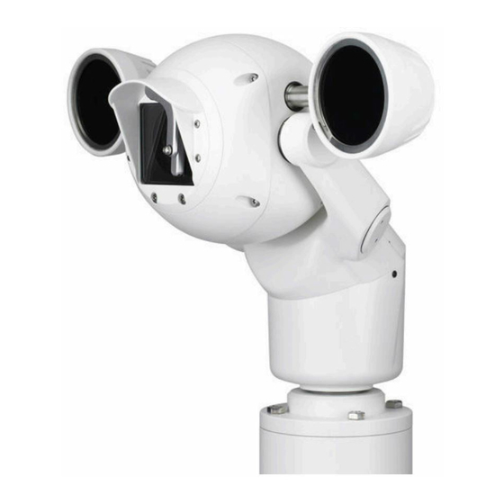
PTZ cameras that have been designed to offer a reliable, robust, and high-quality surveillance solution for extreme security applications. MIC550/MIC550IR models have a 28x or 36x optical zoom (12x digital) and flexible mounting options (upright, inverted, or canted) to achieve the perfect field of view. -
Page 15: Electrical Connections
25 m between the MIC camera and the MIC power supply. For installations that require the camera to be more than 25 m from the power supply, Bosch recommends that a 2 m cable be connected to a junction box (Exd rated for MIC440) from which telemetry, video, and power can be broken out into separate cables and appropriate wiring used to extend the distance to suit. - Page 16 Half Duplex Tx/Rx A Full Duplex Rx B+ Telemetry I/O to RS-422/485 White Half Duplex Tx/Rx B Power Input 2 Low Voltage Power Input Green Power Input 1 Low Voltage Power Input November 2011 | | F.01U.239.454 Operation Manual Bosch Security Systems, Inc.
-
Page 17: Overview Of Installation Steps
(NEC)), Canadian Electrical Code, Part I (also called CE Code or CSA C22.1), ® and all applicable local codes. Bosch Security Systems, Inc. accepts no liability for any damages or losses caused by incorrect or improper installation. To install your MIC camera, follow these steps in sequence. -
Page 18: Select The Mounting Location And Orientation
MIC Series cameras are designed for easy installation in various locations such as directly onto buildings and dedicated CCTV poles. Bosch sells a complete series of mounting brackets designed to allow the camera to achieve the optimal field of view. - Page 19 Figure 6.2: Typical wall mount (from left: Wall Mount Bracket (MIC-WMB), Shallow Conduit Adapter (MIC- SCA), and Spreader Plate (MIC-SPR)) Figure 6.3: Typical corner mount (from left: Wall Mount Bracket (MIC-WMB), Shallow Conduit Adapter (MIC-SCA), and Corner Mount Bracket (MIC-CMB)) Bosch Security Systems, Inc. Operation Manual November 2011 | | F.01U.239.454...
-
Page 20: Select The Mounting Location
If the camera is installed in a highly exposed location where lightning strikes may occur, then Bosch recommends installing a separate lightning conductor within 0.5 m (1.6 ft) of the camera and at least 1.5 m (4.9 ft) higher than the camera. A good earth bonding connection to the camera housing itself will provide protection against damage from secondary strikes. -
Page 21: Considerations For Inverted Cameras
Install the Mounting Brackets 3. Install the mounting brackets. Observe all appropriate safety precautions and local building regulations. Refer to the MIC Series Mounting Brackets Installation Guide for installation instructions. Bosch Security Systems, Inc. Operation Manual November 2011 | | F.01U.239.454... -
Page 22: Mount The Camera
Screw the cable connector sleeve onto the plug until it is secured firmly (approximately four (4) turns from the start of thread engagement). November 2011 | | F.01U.239.454 Operation Manual Bosch Security Systems, Inc. -
Page 23: Earthing The Camera
The PSU "Earth Link" may be used for this purpose. – If dual earthing is unavoidable, then a video isolation transformer should be fitted between the two earths. Bosch Security Systems, Inc. Operation Manual November 2011 | | F.01U.239.454... -
Page 24: Finalize Camera Mounting
The upright unit can be mounted either with the camera ball up or down. So that the picture from a camera installed with the camera ball down appears properly, rotate the camera tilt axis 180°. For more information, see Configuring the Camera for Inverted Operation. November 2011 | | F.01U.239.454 Operation Manual Bosch Security Systems, Inc. -
Page 25: Reverse The Rain Shield For Inverted Operation
Two screws are on the left of the rain shield; two screws are on the right of the rain shield. Figure 10.2: Screw removal Reverse the rain shield. Reattach the rain shield to the camera face. Figure 10.3: Inverted rain shield installed on camera Bosch Security Systems, Inc. Operation Manual November 2011 | | F.01U.239.454... -
Page 26: Install The Mic Power Supply Unit (Psu)
Use only the power supply specified for your specific model of camera. Bosch provides a range of power supply units (PSUs) for MIC Series cameras. These units have a variety of common voltages and provide all the connections needed for power, telemetry and video. -
Page 27: Alarm Inputs
11.3 Simultaneous IP and Analog Video/Control ("Hybrid" Operation) The figure below illustrates how to configure your system to achieve simultaneous video and control over both IP and analog connections. Bosch Security Systems, Inc. Operation Manual November 2011 | | F.01U.239.454... - Page 28 Connection between BNC T-connector and Bilinx-based control (head-end) system Connection between Bilinx-based control (head-end) system and Local Area Network (LAN) (or the "cloud") Connection between the Local Area Network (LAN) and PC connected to video monitor November 2011 | | F.01U.239.454 Operation Manual Bosch Security Systems, Inc.
-
Page 29: Getting Started
RS-485 is capable of controlling a true multidrop network and is specified for up to 32 drivers and 32 receivers on a single 2-wire bus. The MIC550 camera uses the 2-wire mode, although RS-485 can be connected in a 2- or 4-wire mode. -
Page 30: Powering On
MIC Series 550 Notice! For MIC550, the wire shield must be tied to signal at both ends, if 2-wire twisted pair is used. After connecting the wires for RS-485 operation, ensure that the slide switch on the main board to the camera head is positioned toward the LEDs (default). -
Page 31: Navigating The On-Screen Display (Osd) Menus
Note: To select the Exit Menu item from anywhere in the current menu, use the Zoom command. 12.3.3 Keyboard Commands, Bosch Protocol Keyboard control commands are composed of a sequence of three (3) inputs with the following convention: 1) a Function key + 2) a Command number key(s) + 3) the Enter key. -
Page 32: Keyboard Commands, Pelco Protocol
For example, the keyboard command to make the camera pan 360º continuously is: ON-1-ENTER (Press the ON key, then press the number 1 key, and then press ENTER.) Refer to Keyboard Commands (Bosch Protocol) By Number for a complete list of commands. 12.3.4... -
Page 33: Special Preset Commands, Pelco Protocol
Starts an AutoScan. Notice! Some Pelco controllers do not support all of the preset command numbers. Refer to the documentation of the specific Pelco controller for supported preset commands. Bosch Security Systems, Inc. Operation Manual November 2011 | | F.01U.239.454... -
Page 34: About Setting The Camera Address Via Fastaddress
FastAddress, Pelco Protocols This section provides instructions to set a FastAddress with a Pelco keyboard or controller. – A MIC550 with an address set to 0 responds to commands set to any address. – Pelco-P protocol must use addresses 1 to 32. -
Page 35: Setting Passwords
9999 Disables all security and allows all users to access locked commands. 12.7.2 Setting Passwords, Bosch Protocol To set or change a password (locked command): Press OFF-90-ENTER to turn off the command lock. Press SET-802-ENTER to access the password menu. -
Page 36: On-Screen Display (Osd) Menus (Bosch Protocol)
| On-Screen Display (OSD) Menus (Bosch Protocol) MIC Series 550 On-Screen Display (OSD) Menus (Bosch Protocol) 13.1 Camera Setup Menu The Camera Setup Menu contains settings that can be changed/customized for the optical (visible) camera. Camera Setup Exit... * White Bal:... - Page 37 MIC Series 550 On-Screen Display (OSD) Menus (Bosch Protocol) | en Option Description Outdoor W.B. Optimizes camera color for typical outdoor conditions. AWB Hold Sets the camera's color settings for the current scene. Manual Allows users to adjust the Red and Blue gain. Sliding scale: –(1 to...
-
Page 38: Lens Setup Menu
| On-Screen Display (OSD) Menus (Bosch Protocol) MIC Series 550 Determines if color processing remains in effect while in night mode. Options: ON, OFF (default setting). Night Mode Threshold Adjusts the level of light at which the camera automatically switches out of night mode (B/W) operation. -
Page 39: Ptz Setup Menu
MIC Series 550 On-Screen Display (OSD) Menus (Bosch Protocol) | en Option Description CONSTAN Auto Focus is always active, even while the camera is moving. MANUAL Auto Focus is inactive; manual focus must be used. SPOT (Default setting) The camera activates Auto Focus after the camera stops movement. - Page 40 | On-Screen Display (OSD) Menus (Bosch Protocol) MIC Series 550 PTZ Setup * Inactivity: * Inact. Period: 2 min * Autopivot: * Orientation NORMAL * Freeze Frame on Preposition Tilt Up Limit... Azimuth Zero... Restore Defaults... * = Factory Setting...
-
Page 41: Display Setup Menu
MIC Series 550 On-Screen Display (OSD) Menus (Bosch Protocol) | en Sets the time period of inactivity before the above action occurs. Sliding scale: – (3 sec. to 10 min.) +. Default setting: 2 min. Autopivot Automatically rotates the camera 180º when following a subject traveling directly beneath the camera. - Page 42 | On-Screen Display (OSD) Menus (Bosch Protocol) MIC Series 550 Display Setup Edit Scene Title... Restore Defaults... * = Factory Setting Focus / Iris: Select Title OSD Controls how the OSD displays sector or shot titles. Options: Option Description Titles are hidden.
-
Page 43: Communication Setup Menu
MIC Series 550 On-Screen Display (OSD) Menus (Bosch Protocol) | en Privacy Masking Allows masking of sensitive areas. Select option Mask and follow the on-screen instructions to set a mask for up to 24 privacy masks are available, with a maximum limit of eight (8) to a scene. -
Page 44: Alarm Setup
| On-Screen Display (OSD) Menus (Bosch Protocol) MIC Series 550 Baud Rate Manually sets the baud rate when AutoBaud is set to OFF. Options are 2400, 4800, 9600 (default setting), 19200, 38400, and 57600. Bilinx Activates Bilinx control communication. (Only available when not connected to a Bilinx data interface unit.) Options: ON (default setting), OFF. - Page 45 MIC Series 550 On-Screen Display (OSD) Menus (Bosch Protocol) | en Multi Alarm Setup Allows setup of multiple alarms. Options: On; Off. Checkbox button to "Select." Inputs Setup Submenu Choices: Inputs Setup Defines physical inputs or events and commands that can be used in a rule. There are twelve (12) alarm inputs available.
- Page 46 | On-Screen Display (OSD) Menus (Bosch Protocol) MIC Series 550 Outputs Setup... 5. NONE 6. NONE 7. NONE 8. NONE 9. NONE 10. NONE 11. NONE 12. NONE Focus / Iris: Select Type Right / Left: Select Mode Outputs Setup Submenu Choices: Outputs Setup Defines physical outputs and keyboard commands for use in a rule.
- Page 47 MIC Series 550 On-Screen Display (OSD) Menus (Bosch Protocol) | en Rule Setup... Rule 1 Exit... Exit... 1. Rule 1 Enabled Enabled 2. Rule 2 Disable Input: 3. Rule 3 Invalid NONE 4. Rule 4 Empty NONE 5. Rule 5...
-
Page 48: Language Menu
| On-Screen Display (OSD) Menus (Bosch Protocol) MIC Series 550 Selecting a Rule number provides access to its configuration menu. The Rule # Menu allows you to configure a rule from previously-defined alarm inputs and outputs. Once an alarm is configured with valid inputs and outputs, it can be turned on or off (enabled or disabled) through its configuration menu. -
Page 49: Diagnostics Menu
MIC Series 550 On-Screen Display (OSD) Menus (Bosch Protocol) | en Language German Portuguese Polish Italian Dutch Russian Czech Focus / Iris: Save and Exit 13.8 Diagnostics Menu The Diagnostics menu contains a list of diagnostic tools and events. Most of these menu items are display items only;... - Page 50 | On-Screen Display (OSD) Menus (Bosch Protocol) MIC Series 550 Diagnostics Thermal Camera Test On/Off Pattern Focus / Iris: Save and Exit Alarm Status Enters the Alarm Status menu and displays the real time status of alarm inputs and outputs.
- Page 51 MIC Series 550 On-Screen Display (OSD) Menus (Bosch Protocol) | en Power Up Events Displays the number of power up events. Low Volt Events Displays the number of times that the camera dropped below the acceptable voltage limit. Video Loss Events Displays the number of time that video was lost.
-
Page 52: On-Screen Display (Osd) Menus (Pelco Protocol)
Accesses adjustable camera settings such as White Balance and Night Mode. PTZ Setup Accesses adjustable pan/tilt/zoom (PTZ) settings such as tours, scan speed, edit presets, limit stops, recording, and AutoPivot settings. Edit Password Changes the password. November 2011 | | F.01U.239.454 Operation Manual Bosch Security Systems, Inc. -
Page 53: Bosch Menu
If commands are locked and you press Focus or Iris, the camera displays the on-screen message: “Command is Locked.” 14.1 Bosch Menu The Bosch Menu allows full access to the main Setup Menu and all camera configuration settings. Pelco menu Bosch menu... -
Page 54: Camera Setup
INTERMITTENT: Wipes twice, then turns off after 15 seconds. ONE SHOT: Wipes five times, then turns off. WASH WIPE: Wiper washes and wipes. November 2011 | | F.01U.239.454 Operation Manual Bosch Security Systems, Inc. -
Page 55: Ptz Setup
Sliding scale: – (3 sec. to 10 min.) + 5 sec. waiting time between presets. Scan Speed Changes the Autopan and Sliding scale: – (1°/sec to 60°/sec) 30°/ AutoScan speeds. sec. Bosch Security Systems, Inc. Operation Manual November 2011 | | F.01U.239.454... -
Page 56: Aux Setup Menu
The AUX Setup menu provides an area to remain Aux commands. AUX Setup Exit... * WASH WIPE * Alarm Output 2: * Not Set Not Set Not Set Not Set * = Factory Setting Focus / Iris: Select November 2011 | | F.01U.239.454 Operation Manual Bosch Security Systems, Inc. -
Page 57: Other Menus
Restores all settings to their original factory default settings. Reset All Memory Restores all settings to their original factory default settings and clears all user programmed settings such as preset scenes and recordings. Bosch Security Systems, Inc. Operation Manual November 2011 | | F.01U.239.454... -
Page 58: Common User Commands
| Common User Commands MIC Series 550 Common User Commands This chapter details common user commands. See Keyboard Commands (Bosch Protocol) By Number, page 69 for a complete list of commands. 15.1 Programming the Inactivity Operation You can program the MIC camera to change its operating mode automatically after a period of inactivity. -
Page 59: Configuring Preposition Tours
For example, to remap the Aux command for the wiper in the MIC550 camera to match the number of the Aux command used in an existing installation, follow these steps: 1. -
Page 60: Using The Wiper/Washer (Bosch Protocol)
If you prefer not to see this freeze frame, you can turn off the Freeze Frame on Preposition in the PTZ Setup menu. 15.8 Using the Wiper/Washer (Bosch Protocol) To activate the washer/wiper function, press ON-105-ENTER and confirm this sequence: The wiper moves to a predefined position. - Page 61 Auto Auto Camera enters Night Mode Use this for manual with Aux 57 or alarms. control of Night Mode. Model: MIC550 (standard/non-IR) Settin Auto -- When using external IR For control of IR Focus lamps, user must control Correction with a...
-
Page 62: Advanced Features
Set the first input to Alarm Input 1. Set the first output to OSD. Set the second output to Shot 7. Set the third output to Transmit. Enable the Alarm Rule: Highlight Enabled and select YES. November 2011 | | F.01U.239.454 Operation Manual Bosch Security Systems, Inc. -
Page 63: Pre-Position Tour
Masks can be programmed with three, four, or five corners each. Each mask can appear in black, white, or blurred. Blurred is useful when privacy is an issue, but determining the presence of motion is still required. Bosch Security Systems, Inc. Operation Manual November 2011 | | F.01U.239.454... -
Page 64: Image Stabilization
16.5 Azimuth, Elevation, and Compass Directions The MIC550 or the MIC612 allows a user to display the azimuth and elevation position, and the compass heading of the camera. The MIC550 or the MIC612 displays the position data in the lower-right corner of the image display. These readings are described as: Azimuth The pan angle from zero to 359 degrees in one degree increments. -
Page 65: Setting The Azimuth Zero Point
16.5.1 Setting the Azimuth Zero Point The MIC550 or the MIC612 uses the Azimuth Zero point, usually set to magnetic North, as the zero degree pan position and as the North compass heading. The MIC550 or the MIC612 then displays the azimuth reading and the compass heading based on the number of degrees from the Azimuth Zero point. -
Page 66: Maintenance And Troubleshooting
No User-serviceable Parts Except for the external wiper blade, the device contains no user-serviceable parts. Contact your local Bosch service center for device maintenance and repair. In the event of failure, the device should be removed from site for repair. - Page 67 – Check that the maximum Ethernet cable distance has not been exceeded. If O.K., then: – Restore all camera settings. Background is too bright to see Turn on backlight compensation. subject. Bosch Security Systems, Inc. Operation Manual November 2011 | | F.01U.239.454...
-
Page 68: Technical Data
| Technical data MIC Series 550 Technical data For product specifications, see the datasheet for your camera, available on the appropriate product pages of the Online Product Catalog at www.boschsecurity.com. November 2011 | | F.01U.239.454 Operation Manual Bosch Security Systems, Inc. -
Page 69: Appendices
MIC Series 550 Appendices | en Appendices 19.1 Keyboard Commands (Bosch Protocol) By Number 19.1.1 Commands, Optical Camera Locked Functio Command Command Description n Key On/Off Scan 360° / Auto Pan (Continuous) Activates/deactivates Autopan without limits. On/Off Autopan (within Limits) Activates/deactivates Autopan between limits. - Page 70 IR illumination is present. On/Off Alarm Rule Activation/Deactivation On–Enables all alarm rules. Off–Disables all alarm rules. Re-initialize Camera Performs camera/lens re-initialization functions. On/Off Digital Zoom Lock Turns digital zoom on and off. November 2011 | | F.01U.239.454 Operation Manual Bosch Security Systems, Inc.
- Page 71 Off - Switches view to optical camera. Factory P/T Home Position Recalibrates home position; can be used as an Alarm Output. On/Off Record A Activates/deactivates recording A. On/Off Record B Activates/deactivates recording B. Bosch Security Systems, Inc. Operation Manual November 2011 | | F.01U.239.454...
- Page 72 Enters the Standard Tour Scene menu. Shot Edit Tour 2 (Custom) Enters the Custom Tour Scene menu. Set/ 901-999 Adds/Removes a Preposition Shot Set ###–Adds preset. Shot from Tour 1 Shot ###–Removes preset. November 2011 | | F.01U.239.454 Operation Manual Bosch Security Systems, Inc.
- Page 74 Bosch Security Systems, Inc. Bosch Sicherheitssysteme GmbH 850 Greenfield Road Robert-Bosch-Ring 5 Lancaster, PA, 17601 85630 Grasbrunn Germany www.boschsecurity.com © Bosch Security Systems, Inc., 2014...
Need help?
Do you have a question about the MIC550 and is the answer not in the manual?
Questions and answers