
Related Manuals for Avaya AP 8120 series


Summary of Contents for Avaya AP 8120 series
- Page 1 Avaya WLAN 8100 Installation – AP 8120 Series 1.2.0.0 NN47251-302, 03.02 April 2012...
- Page 2 Product provided by Avaya including the selection, arrangement and While reasonable efforts have been made to ensure that the design of the content is owned either by Avaya or its licensors and is information in this document is complete and accurate at the time of protected by copyright and other intellectual property laws including the printing, Avaya assumes no liability for any errors.
-
Page 3: Table Of Contents
Installing the Power over Ethernet injector....................66 Chapter 8: Configuring the AP 8120 series..............Configuring the AP 8120 series access points using WMS..............71 Configuring the AP 8120 series using the CLI..................73 Assigning IEEE 802.11a/b/g channel designations to the AP 8120 and AP 8120 with External Antenna 74 Assigning channel designations to the AP 8120-O................... - Page 4 Radiation maps for AP 8120 Tyco external antennas..............126 AP8120-O antenna specifications......................156 Radiation maps for the Masterwave 2.4 GHz antenna..............157 Radiation maps for the Masterwave 5 GHz antenna................ 166 Avaya WLAN 8100 Installation – AP 8120 Series April 2012...
-
Page 5: Chapter 1: New In This Release
Chapter 1: New in this release The following sections details what’s new in Avaya WLAN 8100 Installation – AP 8120 Series (NN47251-302) for Release 1.2. Features The AP 8120-O is a 2x2 outdoor dual concurrent access point providing 2.4 GHz and 5 GHz Radio Frequencies (RF). - Page 6 New in this release Avaya WLAN 8100 Installation – AP 8120 Series April 2012 Comments? infodev@avaya.com...
-
Page 7: Chapter 2: Purpose Of This Document
Chapter 2: Purpose of this document This document provides information and procedures for the physical installation of the WLAN 8100 AP 8120 series of access points. The AP 8120 series consist of the following models: • AP 8120 • AP 8120 with External Antenna •... - Page 8 Purpose of this document Avaya WLAN 8100 Installation – AP 8120 Series April 2012 Comments? infodev@avaya.com...
-
Page 9: Chapter 3: Indoor Installation Reference
Access Point 8120 The Avaya Access Point 8120 (AP 8120) is the wireless access portion of the Avaya WLAN 8100 Series solution. The AP 8120 provides 802.11a+n b/g+n wireless connectivity through six dual-band 2.4/5.0 GHz antennas; three dedicated to 2.4 GHz use and three dedicated to 5.0 GHz . -
Page 10: Access Point 8120 And Access Point 8120 With External Antenna External Hardware Features
Mounting options on page 14 • Status light-emitting diode on page 14 Access Point 8120 front view The following diagram illustrates the front view of the Access Point 8120. Avaya WLAN 8100 Installation – AP 8120 Series April 2012 Comments? infodev@avaya.com... - Page 11 Access Point 8120 and Access Point 8120 with External Antenna external hardware features Figure 1: Front view of the Access Point 8120 Access Point 8120 rear view The following diagram illustrates the rear view of the Access Point 8120. Avaya WLAN 8100 Installation – AP 8120 Series April 2012...
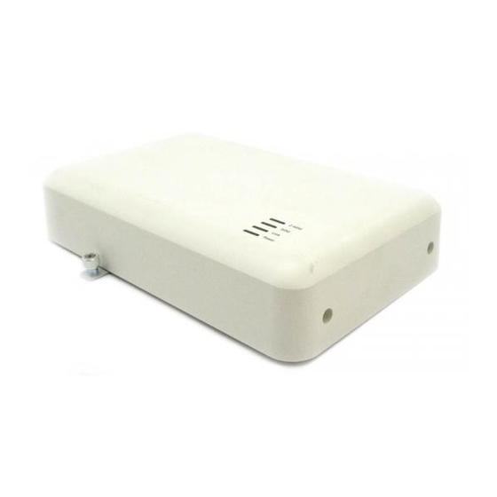
- Page 12 Figure 2: Rear view of the Access Point 8120 Access Point 8120 with External Antenna front view The following diagram illustrates the front view of the Access Point 8120 with External Antenna Avaya WLAN 8100 Installation – AP 8120 Series April 2012 Comments? infodev@avaya.com...
- Page 13 Kensington cable interface The Access Point 8120 and Access Point 8120 with External Antenna has an interface for attaching a Kensington security cable. The cable is not included with the access point. Avaya WLAN 8100 Installation – AP 8120 Series April 2012...
- Page 14 Unlit The access point does not have network connectivity. AP Power Solid red (POST) The access point is performing power on self Solid green (Boot) test (POST). Avaya WLAN 8100 Installation – AP 8120 Series April 2012 Comments? infodev@avaya.com...
- Page 15 Access Point 8120 and Access Point 8120 with External Antenna external hardware features Appearance Meaning The access point is receiving power after boot Unlit The access point is not receiving power. Avaya WLAN 8100 Installation – AP 8120 Series April 2012...
- Page 16 Indoor installation reference Avaya WLAN 8100 Installation – AP 8120 Series April 2012 Comments? infodev@avaya.com...
-
Page 17: Chapter 4: Outdoor Installation Reference
• equipped with internal surge protectors for its four antennas and Ethernet port. • powered by a 802.3at standard compliant Power Over Ethernet (PoE+). • an Avaya-optional indoor surge arrester. The surge arrester provides surge protection for indoor equipment that is connected to the AP 8120-O through an Ethernet cable. For more... -
Page 18: Access Point 8120-O Hardware Features
This section contains information on the external hardware features of the Access Point 8120- Access Point 8120-O front view The following diagram illustrates the front view of the Access Point 8120-O showing attached antennas. Avaya WLAN 8100 Installation – AP 8120 Series April 2012 Comments? infodev@avaya.com... - Page 19 Figure 5: Access Point 8120-O front view with attached antennas Access Point 8120-O rear view The following diagram illustrates the rear view of the Access Point 8120-O showing empty antenna connectors. Avaya WLAN 8100 Installation – AP 8120 Series April 2012...
- Page 20 Access Point 8120-O bottom view The following diagram illustrates the bottom view of the Access Point 8120-O showing the Ethernet connector. Figure 7: Access Point 8120-O bottom view Avaya WLAN 8100 Installation – AP 8120 Series April 2012 Comments? infodev@avaya.com...
-
Page 21: Mounting Options
802.11b 1/2/5.5/11 Mbps at 26 dBm 802.11g • 6/9/12/18/24 Mbps at 26 dBm • 36 Mbps at 25 dBm • 48 Mbps at 24 dBm • 54Mbps at 23 dBm Avaya WLAN 8100 Installation – AP 8120 Series April 2012... - Page 22 • MCS4/ MCS5 at -78/-75 dBm (5GHz), -87/ -84dBm (2.4GHz) • MCS6/ MCS7 at -72/ -70 dBm (5GHz), -80/-78dBm(2.4GHz) • MCS8 up to MCS11 at -89/-87/-84/-81 dBm (5GHz), -96/ -95/ -90/-88dBm (2.4GHz) Avaya WLAN 8100 Installation – AP 8120 Series April 2012 Comments? infodev@avaya.com...
- Page 23 (2.4GHz) Temperatures Operating Temperature: -40° C to +60 °C (Non-condensing) Humidity 90% or less (Non- condensing) Storage Temperature: -40° C to +70° C (Non-condensing) Humidity: 95% or less (Non- condensing) Avaya WLAN 8100 Installation – AP 8120 Series April 2012...
- Page 24 Outdoor installation reference Avaya WLAN 8100 Installation – AP 8120 Series April 2012 Comments? infodev@avaya.com...
-
Page 25: Chapter 5: Installation Preparation
- four adhesive rubber feet • Avaya WLAN 8100 Regulatory Information - AP 8120 (NN47251–104) • Avaya WLAN 8100 Regulatory Information - AP 8120 with External Antenna (NN47251– 109) Verify that the items removed from the shipping carton correspond to the provided list. If an item is missing or damaged, contact Avaya. -
Page 26: Cable Requirements For The Indoor Access Points
The following cabling section applies to the AP 8120 and AP 8120 with External Antenna only. The AP 8120 series access points have one RJ-45 port. This port provides a 10/100/1000BASE-TX Ethernet connection to a Wireless Controller 8180. This port is used to indirectly connect an access point to a WC 8180 through an intermediate Layer 2 or Layer 3 network. -
Page 27: Cable Requirements For Outdoor Access Points
Avaya recommends using only a certified outdoor UTP cable such as the Cat5E. The AP 8120-O access point has one RJ-45 port that provides a 10/100/1000BASE-TX Ethernet connection that is used to indirectly connect the access point to an Avaya WC 8180 Avaya WLAN 8100 Installation – AP 8120 Series... -
Page 28: Waterproofing The Ethernet Utp Cable
Avaya strongly recommends that you use an outdoor CAT-5E Ethernet cable for all external connections. The AP 8120-O supports 802.3at (also known as PoE+). Avaya recommends that you use an Avaya-provided PoE power injector when operating the AP 8120-O. The access point receives power and data through the RJ-45 port. - Page 29 9. Slide the compression grommet into the body of the feed through. 10. Push the cable through the compression cap to the feed through body by hand to tighten the seal. Figure 9: Waterproofing the Ethernet plug Avaya WLAN 8100 Installation – AP 8120 Series April 2012...
-
Page 30: Management Software
PIN 8– Solid brown Management software If you are using the WLAN Management Software (WMS) to plan your Avaya Mobility System installation, you can create and verify a network plan for the entire Avaya network installation and generate an AP work order, before installing any access points. -
Page 31: Outdoor Access Point Site Planning
Avaya recommends that you use outdoor CAT5E Ethernet cable for all external connections. Antenna Caution: Only use the provided Avaya-approved antennas with the WLAN AP 8120-O. A WLAN AP 8120-O that is outfitted with non-certified Avaya antennas is not supported under Avaya support agreements. Wireless Controller 8180 recommendation Avaya recommends that you install and configure the Wireless Controller 8180 before installing an AP. -
Page 32: Wall Installation Recommendations For Indoor Aps
Avaya approved 802.3af power injector. The AP 8120-O requires an 802.3at- 802.3af-compliant source or an Avaya approved 802.3at power injector. Connecting an AP to a Power over Ethernet (PoE) device that is not approved by Avaya can damage the equipment. -
Page 33: Safety Precautions For Outdoor Access Points
Powerline Warning: Avaya warns that failure to comply with power and safety instructions could cause harm to persons and equipment. Ensure that the following precautions are implemented: Warning: Coming in contact with power lines can be lethal. - Page 34 The AP 8120-O is equipped with internal surge protectors for its four antennas and its Ethernet port. Before operating the unit, you must ensure to properly ground the AP 8120-O. The Avaya- provided series indoor Ethernet surge arrester (lightning protector) provides high-level protection for the Ethernet and/or Power over Ethernet (POE) equipment located inside the building.
-
Page 35: Additional Radio Safety Advisories
Before using a wireless device in a hazardous location, consult the local codes, national codes, and safety directors of the location for usage constraints. Caution: The Avaya WLAN AP 8120-O radios are disabled by default and can be enabled only by a system administrator. Voltage: Danger —... - Page 36 Installation preparation Avaya WLAN 8100 Installation – AP 8120 Series April 2012 Comments? infodev@avaya.com...
-
Page 37: Chapter 6: Indoor Access Point Installation
7-10 in·lbf (0.8–1.1 N·m) for stainless steel connectors. Flats are also provided on the cable side of the connector assembly so that you use a second wrench to prevent it rotating and damaging the joint to the cable. Avaya also recommends that you clean out loose debris from the internal surfaces before connecting. - Page 38 2. Install the screws into the wall anchors but do not seat them fully, leave at least a 2 mm gap between the screw head and the wall. Avaya WLAN 8100 Installation – AP 8120 Series April 2012 Comments? infodev@avaya.com...
- Page 39 4. Tighten the screws to secure the wall mounting bracket tightly against the wall. 5. Align the mounting tabs on the bottom of the access point sheet metal enclosure with the vertically oriented keyhole slots in the mounting bracket. Avaya WLAN 8100 Installation – AP 8120 Series April 2012...
- Page 40 AP 8120 with External Antenna inputs with the cables. The 180 degree TYCO antenna connectors are labeled the same as the AP 8120 with External Antenna inputs. Avaya WLAN 8100 Installation – AP 8120 Series April 2012 Comments? infodev@avaya.com...
-
Page 41: Installing An Access Point With A Ceiling Grid Adaptor
7-10 in·lbf (0.8–1.1 N·m) for stainless steel connectors. Flats are also provided on the cable side of the connector assembly so that you use a second wrench to prevent it rotating and damaging the joint to the cable. Avaya also recommends that you clean out loose debris from the internal surfaces before connecting. - Page 42 3. Mount the larger bracket to the grid. While installing, pay attention to the width of the grid strip in order to ascertain the appropriate orientation for the smaller bracket which is installed next. Avaya WLAN 8100 Installation – AP 8120 Series April 2012 Comments? infodev@avaya.com...
- Page 43 Use a screwdriver to screw down the captive fastener. Securing the two brackets in this manner is essential to prevent them from disengaging from one another. Tighten the captive fastener screw securely. Avaya WLAN 8100 Installation – AP 8120 Series April 2012...
- Page 44 If you are installing Laird antennas with articulated mount, you must attach the antennas to a mast or a vertical surface using the articulated mount and mounting bolts. Laird antenna Avaya WLAN 8100 Installation – AP 8120 Series April 2012 Comments? infodev@avaya.com...
- Page 45 2.5G #1 2.5G #2 2.5G #3 5G #1 5G #2 5G #3 with External Antenna inputs/ 180 degree TYCO antenna 70 degree V-Pol H-POL V-POL V-Pol H-POL V-POL Laird antenna inputs Avaya WLAN 8100 Installation – AP 8120 Series April 2012...
- Page 46 Indoor access point installation 9. Make electrical connections and return ceiling tiles. Avaya WLAN 8100 Installation – AP 8120 Series April 2012 Comments? infodev@avaya.com...
-
Page 47: Chapter 7: Outdoor Access Point Installation
1. Locate the enclosure cover bolt next to a ground signal. 2. Using an adjustable wrench, loosen the bolt. 3. Using the provided green ground wire, insert the spade lug underneath the bolt. Avaya WLAN 8100 Installation – AP 8120 Series April 2012... -
Page 48: Installing The Wlan Ap 8120-O On A Vertical Pole
Earth ground using the shortest and most direct run. Installing the WLAN AP 8120-O on a vertical pole About this task Complete the following procedure to mount the WLAN AP 8120-O on a vertical pole. Avaya WLAN 8100 Installation – AP 8120 Series April 2012 Comments? infodev@avaya.com... - Page 49 Figure 11: Attaching the plane bracket to backcase 2. Drive the screws to attach the plane bracket to the back case. 3. Align the tab holes of the static brackets horizontally to the pole. Avaya WLAN 8100 Installation – AP 8120 Series April 2012...
- Page 50 5. Select a 2.5" or 5" hose strap depending on the diameter of the pole. Thread the open end of the hose strap through the two tabs on the static bracket. Avaya WLAN 8100 Installation – AP 8120 Series April 2012...
- Page 51 Grounding the WLAN AP 8120-O on page 47. 9. Insert Avaya 5 GHz antennas as required into the connectors at the top of the WLAN AP 8120-O. Tighten the antennas by hand. 10. Insert Avaya 2.4 GHz antennas as required into the connectors at the bottom of the WLAN AP 8120-O Tighten the antennas by hand.
- Page 52 Ethernet surge arrester and PoE to the WLAN AP 8120-O. Note: If you are using the Avaya PoE injector, you are not required to use the supplied Ethernet surge arrester as the Avaya PoE injector has internal surge protection.
-
Page 53: Mounting The Wlan Ap 8120-O On A Horizontal Pole
Figure 16: Attaching the plane bracket to backcase 2. Drive the screws to attach the plane bracket to the back case. 3. Align the static brackets tab holes vertically to the pole. Avaya WLAN 8100 Installation – AP 8120 Series April 2012... - Page 54 5. Select a 2.5" or 5" hose strap depending on the diameter of the pole. Thread the open end of the hose strap through the two tabs on the static bracket. Avaya WLAN 8100 Installation – AP 8120 Series April 2012...
- Page 55 7. Verify that the WLAN AP 8120-O is attached securely to the pole. 8. Ground the WLAN AP 8120-O to a proper Earth ground using the procedure in Grounding the WLAN AP 8120-O on page 47. Avaya WLAN 8100 Installation – AP 8120 Series April 2012...
- Page 56 Outdoor access point installation 9. Insert Avaya 5 GHz antennas as required into the connectors at the top of the WLAN AP 8120-O. Tighten the antennas by hand. 10. Insert Avaya 2.4 GHz antennas as required into the connectors at the bottom of the WLAN AP 8120-O.
-
Page 57: Installing The Wlan Ap 8120-O On A Wall
Installing the WLAN AP 8120-O on a wall b. To connect the Avaya PoE injector to the WLAN AP 8120-O, see Installing the Power over Ethernet injector on page 66. Installing the WLAN AP 8120-O on a wall Complete the following procedure to mount the WLAN AP 8120-O on a wall. - Page 58 Figure 22: Drilling holes into surface 3. Hammer the bolt into each of the holes that you drilled. 4. Place the lock and flat washers on the four hex cap screws. Avaya WLAN 8100 Installation – AP 8120 Series April 2012 Comments? infodev@avaya.com...
- Page 59 Figure 23: Attaching the plane bracket 5. Drive the screws to attach the plane bracket to the back case. 6. Tighten the flat washers to secure the bracket to the mounting surface. Avaya WLAN 8100 Installation – AP 8120 Series April 2012...
- Page 60 Grounding the WLAN AP 8120-O on page 47. 9. Insert Avaya 5 GHz antennas as required into the connectors at the top of the WLAN AP 8120-O. Tighten the antennas by hand. 10. Insert Avaya 2.4 GHz antennas as required into the connectors at the bottom of the WLAN AP 8120-O Tighten the antennas by hand.
- Page 61 Ethernet surge arrester and PoE injector to the WLAN AP 8120-O. Note: If you are using the Avaya PoE injector, you are not required to use the supplied Ethernet surge arrester as the Avaya PoE injector has internal surge protection.
-
Page 62: Installing The Ethernet Surge Arrester
PoE. For a typical installation, refer to the following diagram. Note: If you are using the Avaya PoE injector, you are not required to connect the Ethernet surge arrester because the Avaya PoE injector already has internal surge protection. - Page 63 3. Using a certified grounding wire, screw one end of a copper grounding wire to the large ground screw located between the two RJ-45 connectors as shown in the following diagram. Avaya WLAN 8100 Installation – AP 8120 Series April 2012...
- Page 64 6. Insert the wateproofed end of the Ethernet cable into the bottom of the WLAN AP 8120-O, tightening in place by hand. See the waterproofing the Ethernet UTP cable section,Waterproofing the Ethernet UTP cable on page 28 for waterproofing the Ethernet cable. Avaya WLAN 8100 Installation – AP 8120 Series April 2012 Comments? infodev@avaya.com...
- Page 65 8. Replace the top of the Ethernet surge arrester, ensuring the ground wire feeds through the center opening and the Ethernet cables are fed through their respective openings at the bottom of the Ethernet surge arrester. Avaya WLAN 8100 Installation – AP 8120 Series April 2012...
-
Page 66: Installing The Power Over Ethernet Injector
802.3af and 802.3at compliant. When using the PD-9001G-40/SP, you are not required to use the Ethernet surge arrester provided with the AP 8120-O. For Release 1.2, the Avaya PoE injector is certified for use only in North America and the European Union. - Page 67 Figure 29: Copper ground post on PoE 3. Connect the other end to a working AC outlet. 4. Insert one end of an Ethernet cable into the DATA IN port on the PoE injector. Avaya WLAN 8100 Installation – AP 8120 Series April 2012...
- Page 68 Outdoor access point installation Figure 30: PoE DATA IN and DATA & POWER ports 5. Connect the other end to the Avaya WLAN switch. The AC indicator lights up. Figure 31: PoE AC and PORT indicators 6. Insert the waterproofed connection of Ethernet cable into the Ethernet connector found at the bottom of the WLAN AP 8120-O .
- Page 69 Figure 32: AP 8120-O PoE deployment 7. Insert the other end of the weatherproofed Ethernet cable into the DATA & POWER OUT port on the PoE injector. The Port indicator lights up. Avaya WLAN 8100 Installation – AP 8120 Series April 2012...
- Page 70 Outdoor access point installation Avaya WLAN 8100 Installation – AP 8120 Series April 2012 Comments? infodev@avaya.com...
-
Page 71: Chapter 8: Configuring The Ap 8120 Series
Chapter 8: Configuring the AP 8120 series This chapter describes the procedures to configure an AP 8120 series access point after mounting and installation. Configuring the AP 8120 series access points using WMS Use this workflow to configure the AP 8120 series access points using the WMS (Wireless Management System) . - Page 72 3 feet. 18. Click Add. For instructions on specifying an AP model or displaying AP information, refer to the Avaya WLAN 8100 WC 8120 CLI Reference NN47251-107 , Displaying AP Avaya WLAN 8100 Installation – AP 8120 Series April 2012...
-
Page 73: Configuring The Ap 8120 Series Using The Cli
Configuring the AP 8120 series using the CLI Use this workflow to configure wireless AP profiles for the AP 8120 series access points using the Command Line Interface (CLI). For a complete list of procedures to configure the AP 8120 series using CLI, see Avaya WLAN 8100 WC 8180 CLI Reference (NN47251-107). -
Page 74: Assigning Ieee 802.11A/B/G Channel Designations To The Ap 8120 And Ap 8120 With External Antenna
5.470 to 5.725 GHz bands IEEE mode Channel Number Frequency (GHz) 5.500 5.520 5.540 5.560 5.580 5.600 5.620 5.640 IEEE mode Channel number Frequency (GHz) 5.660 5.680 5.700 Avaya WLAN 8100 Installation – AP 8120 Series April 2012 Comments? infodev@avaya.com... -
Page 75: Assigning Channel Designations To The Ap 8120-O
Outdoor Canada Same as US Same as US Same as US Outdoor Outdoor Outdoor Italy, Germany, UK Same as EU Same as EU Same as EU France Outdoor Outdoor Outdoor Avaya WLAN 8100 Installation – AP 8120 Series April 2012... - Page 76 Outdoor Outdoor Canada Same as US Same as US Same as US Outdoor Outdoor Outdoor Italy, Germany, UK Same as EU Same as EU Same as EU France Avaya WLAN 8100 Installation – AP 8120 Series April 2012 Comments? infodev@avaya.com...
- Page 77 Table 11: AP 8120-O 2.4 GHZ (40MHz) channel 4–6 designations Channel Number Center Frequency MHz 2437 2442 2447 Outdoor Outdoor Outdoor Canada Same as US Same as US Same as US Avaya WLAN 8100 Installation – AP 8120 Series April 2012...
- Page 78 Table 13: AP 8120-O 5 GHZ (20MHz) Lower channel 36–40 designations Channel Number 5 GHz UNII-1 (Lower) Frequency MHz 5180 5200 Canada Same as US Same as US Italy, Germany, UK Same as EU Same as EU France Avaya WLAN 8100 Installation – AP 8120 Series April 2012 Comments? infodev@avaya.com...
- Page 79 Frequency MHz 5805 5825 Outdoor Outdoor Canada Same as US Same as US Italy, Germany, UK Same as EU Same as EU France Same as EU Same as EU Legend Avaya WLAN 8100 Installation – AP 8120 Series April 2012...
- Page 80 • EU - No non-DFS channels are available. Channels 36 to 48 are only for indoor. Channels 149 to 165 need special licensing. The remaining channels are DFS. Avaya WLAN 8100 Installation – AP 8120 Series April 2012 Comments? infodev@avaya.com...
-
Page 81: Chapter 9: Installation Tools And Utilities
Ceiling installations Universal mounting bracket T-bar clamp Box cutter Small screwdriver (3-mm or 1/8-inch) Junction box Wall mounting Universal mounting bracket Small screwdriver (3-mm or 1/8-inch) #2 Phillips-head screwdriver No Avaya WLAN 8100 Installation – AP 8120 Series April 2012... - Page 82 Installation tools and utilities Avaya WLAN 8100 Installation – AP 8120 Series April 2012 Comments? infodev@avaya.com...
-
Page 83: Chapter 10: Troubleshooting The Indoor Access Point
• the AP was not added to the domain AP database. • show wireless domain ap database 2.4 and 5 GHz LEDs are going A configuration sync was just from blinking green to blue to executed. Avaya WLAN 8100 Installation – AP 8120 Series April 2012... -
Page 84: Chapter 10: Troubleshooting The Indoor Access Point
Troubleshooting the Indoor access point LED State Diagnostics Remedy unlit (for a few seconds) and then back to blinking green and blue Power LED is red. The AP was just reset. Avaya WLAN 8100 Installation – AP 8120 Series April 2012 Comments? infodev@avaya.com... -
Page 85: Appendix A: External Image Upgrade
AP and the AP downloads the image from the external web server. 5. Once the download completes and the image is written to AP flash, the AP goes for a reset. Avaya WLAN 8100 Installation – AP 8120 Series April 2012... - Page 86 7. If there is a mismatch in the versions, the existing status flag updates. For detailed instructions on downloading, upgrading, and configuring the AP image refer to Avaya WLAN 8100 WC 8120 GUI Reference NN47251-108 , Configuring System Operations and Avaya WLAN 8100 WC 8120 CLI Reference NN47251-107, Managing Wireless Communications Avaya WLAN 8100 Installation –...
-
Page 87: Appendix B: Wlan 8100 Antenna Specifications
WLAN 802.11n MIMO applications For AP via low loss, plenum rated, use with the WLAN AP 8120 with coax pigtail. For use with the External Antenna Avaya WLAN 8100 Installation – AP 8120 Series April 2012... - Page 88 “omni antennas” are actually weaker directly above and below their endpoints creating a coverage pattern that resembles a “doughnut” shape around the antenna. This characteristic is represented Avaya WLAN 8100 Installation – AP 8120 Series April 2012 Comments? infodev@avaya.com...
-
Page 89: Radiation Maps For Ap 8120 Laird External Antennas
Laird antenna radiation pattern: Laird Port 1 (V-POL) The following figures show the H plane and E plane radiation patterns for Port 1 on the Laird antenna. Avaya WLAN 8100 Installation – AP 8120 Series April 2012... - Page 90 WLAN 8100 antenna specifications Figure 33: Laird port 1, 2.4 GHz, H plane Avaya WLAN 8100 Installation – AP 8120 Series April 2012 Comments? infodev@avaya.com...
- Page 91 AP 8120 with External Antenna specifications Figure 34: Laird port 1, 2.4 GHz, E plane Avaya WLAN 8100 Installation – AP 8120 Series April 2012...
- Page 92 WLAN 8100 antenna specifications Figure 35: Laird port 1, 2.45 GHz, H plane Avaya WLAN 8100 Installation – AP 8120 Series April 2012 Comments? infodev@avaya.com...
- Page 93 AP 8120 with External Antenna specifications Figure 36: Laird port 1, 2.45 GHz, E plane Avaya WLAN 8100 Installation – AP 8120 Series April 2012...
- Page 94 WLAN 8100 antenna specifications Figure 37: Laird port 1, 2.5 GHz, H plane Avaya WLAN 8100 Installation – AP 8120 Series April 2012 Comments? infodev@avaya.com...
- Page 95 AP 8120 with External Antenna specifications Figure 38: Laird port 1, 2.5 GHz, E plane Avaya WLAN 8100 Installation – AP 8120 Series April 2012...
- Page 96 WLAN 8100 antenna specifications Figure 39: Laird port 1, 5.15 GHz, H plane Avaya WLAN 8100 Installation – AP 8120 Series April 2012 Comments? infodev@avaya.com...
- Page 97 AP 8120 with External Antenna specifications Figure 40: Laird port 1, 5.15 GHz, E plane Avaya WLAN 8100 Installation – AP 8120 Series April 2012...
- Page 98 WLAN 8100 antenna specifications Figure 41: Laird port 1, 5.47 GHz, H plane Avaya WLAN 8100 Installation – AP 8120 Series April 2012 Comments? infodev@avaya.com...
- Page 99 AP 8120 with External Antenna specifications Figure 42: Laird port 1, 5.47 GHz, E plane Avaya WLAN 8100 Installation – AP 8120 Series April 2012...
- Page 100 WLAN 8100 antenna specifications Figure 43: Laird port 1, 5.9 GHz, H plane Avaya WLAN 8100 Installation – AP 8120 Series April 2012 Comments? infodev@avaya.com...
- Page 101 Figure 44: Laird port 1, 5.9 GHz, E plane Laird antenna radiation pattern: Laird Port 2 (H-Pol) The following figures show the H plane and E plane radiation patterns for Port 2 on the Laird antenna. Avaya WLAN 8100 Installation – AP 8120 Series April 2012...
- Page 102 WLAN 8100 antenna specifications Figure 45: Laird port 2, 2.4 GHz, H plane Avaya WLAN 8100 Installation – AP 8120 Series April 2012 Comments? infodev@avaya.com...
- Page 103 AP 8120 with External Antenna specifications Figure 46: Laird port 2, 2.4 GHz, E plane Avaya WLAN 8100 Installation – AP 8120 Series April 2012...
- Page 104 WLAN 8100 antenna specifications Figure 47: Laird port 2, 2.45 GHz, H plane Avaya WLAN 8100 Installation – AP 8120 Series April 2012 Comments? infodev@avaya.com...
- Page 105 AP 8120 with External Antenna specifications Figure 48: Laird port 2, 2.45 GHz, E plane Avaya WLAN 8100 Installation – AP 8120 Series April 2012...
- Page 106 WLAN 8100 antenna specifications Figure 49: Laird port 2, 2.5 GHz, H plane Avaya WLAN 8100 Installation – AP 8120 Series April 2012 Comments? infodev@avaya.com...
- Page 107 AP 8120 with External Antenna specifications Figure 50: Laird port 2, 2.5 GHz, E plane Avaya WLAN 8100 Installation – AP 8120 Series April 2012...
- Page 108 WLAN 8100 antenna specifications Figure 51: Laird port 2, 5.15 GHz, H plane Avaya WLAN 8100 Installation – AP 8120 Series April 2012 Comments? infodev@avaya.com...
- Page 109 AP 8120 with External Antenna specifications Figure 52: Laird port 2, 5.15 GHz, E plane Avaya WLAN 8100 Installation – AP 8120 Series April 2012...
- Page 110 WLAN 8100 antenna specifications Figure 53: Laird port 2, 5.47 GHz, H plane Avaya WLAN 8100 Installation – AP 8120 Series April 2012 Comments? infodev@avaya.com...
- Page 111 AP 8120 with External Antenna specifications Figure 54: Laird port 2, 5.47 GHz, E plane Avaya WLAN 8100 Installation – AP 8120 Series April 2012...
- Page 112 WLAN 8100 antenna specifications Figure 55: Laird port 2, 5.9 GHz, H plane Avaya WLAN 8100 Installation – AP 8120 Series April 2012 Comments? infodev@avaya.com...
- Page 113 Figure 56: Laird port 2, 5.9 GHz, E plane Laird antenna radiation pattern: Laird Port 3 (V-Pol) The following figures show the H plane and E plane radiation patterns for Port 2 on the Laird antenna. Avaya WLAN 8100 Installation – AP 8120 Series April 2012...
- Page 114 WLAN 8100 antenna specifications Figure 57: Laird port 3, 2.4 GHz, H plane Avaya WLAN 8100 Installation – AP 8120 Series April 2012 Comments? infodev@avaya.com...
- Page 115 AP 8120 with External Antenna specifications Figure 58: Laird port 3, 2.4 GHz, E plane Avaya WLAN 8100 Installation – AP 8120 Series April 2012...
- Page 116 WLAN 8100 antenna specifications Figure 59: Laird port 3, 2.45 GHz, H plane Avaya WLAN 8100 Installation – AP 8120 Series April 2012 Comments? infodev@avaya.com...
- Page 117 AP 8120 with External Antenna specifications Figure 60: Laird port 3, 2.45 GHz, E plane Avaya WLAN 8100 Installation – AP 8120 Series April 2012...
- Page 118 WLAN 8100 antenna specifications Figure 61: Laird port 3, 2.5 GHz, H plane Avaya WLAN 8100 Installation – AP 8120 Series April 2012 Comments? infodev@avaya.com...
- Page 119 AP 8120 with External Antenna specifications Figure 62: Laird port 3, 2.5 GHz, E plane Avaya WLAN 8100 Installation – AP 8120 Series April 2012...
- Page 120 WLAN 8100 antenna specifications Figure 63: Laird port 3, 5.15 GHz, H plane Avaya WLAN 8100 Installation – AP 8120 Series April 2012 Comments? infodev@avaya.com...
- Page 121 AP 8120 with External Antenna specifications Figure 64: Laird port 3, 5.15 GHz, E plane Avaya WLAN 8100 Installation – AP 8120 Series April 2012...
- Page 122 WLAN 8100 antenna specifications Figure 65: Laird port 3, 5.47 GHz, H plane Avaya WLAN 8100 Installation – AP 8120 Series April 2012 Comments? infodev@avaya.com...
- Page 123 AP 8120 with External Antenna specifications Figure 66: Laird port 3, 5.47 GHz, E plane Avaya WLAN 8100 Installation – AP 8120 Series April 2012...
- Page 124 WLAN 8100 antenna specifications Figure 67: Laird port 3, 5.9 GHz, H plane Avaya WLAN 8100 Installation – AP 8120 Series April 2012 Comments? infodev@avaya.com...
- Page 125 Port 1 (V-Pol) Port 2 (V-Pol) Port 3 (V-Pol) 2.4 - 2.5 GHz (dBi) 6.65 6.75 7.15 5.15 - 5.9 GHz (dBi) 8.84 7.68 8.76 H plane 3 dB beam width Avaya WLAN 8100 Installation – AP 8120 Series April 2012...
-
Page 126: Radiation Maps For Ap 8120 Tyco External Antennas
Radiation maps for AP 8120 Tyco external antennas The following sections display radiation maps for the TYCO external antennas for the AP 8120 with external antennas. Figure 69: Tyco radiation graph legend Avaya WLAN 8100 Installation – AP 8120 Series April 2012 Comments? infodev@avaya.com... - Page 127 AP 8120 with External Antenna specifications Figure 70: Tyco antenna radiation pattern: antenna 1, elevation 1, vertical polarization graph Tyco antenna radiation pattern: antenna 1, elevation 1, vertical polarization reference table Avaya WLAN 8100 Installation – AP 8120 Series April 2012...
- Page 128 WLAN 8100 antenna specifications Figure 71: Tyco antenna radiation pattern: antenna 1, elevation 1, horizontal polarization reference graph Tyco antenna radiation pattern: antenna 1, elevation 1, horizontal polarization reference table Avaya WLAN 8100 Installation – AP 8120 Series April 2012 Comments? infodev@avaya.com...
- Page 129 AP 8120 with External Antenna specifications Figure 72: Tyco antenna radiation pattern: antenna 1, elevation 2, vertical polarization graph Tyco antenna radiation pattern: antenna 1, elevation 2, vertical polarization reference table Avaya WLAN 8100 Installation – AP 8120 Series April 2012...
- Page 130 WLAN 8100 antenna specifications Figure 73: Tyco antenna radiation pattern: antenna 1, elevation 2, horizontal polarization reference graph Tyco antenna radiation pattern: antenna 1, elevation 2, horizontal polarization reference table Avaya WLAN 8100 Installation – AP 8120 Series April 2012 Comments? infodev@avaya.com...
- Page 131 AP 8120 with External Antenna specifications Figure 74: Tyco antenna radiation pattern: antenna 1, azimuth vertical polarization graph Tyco antenna radiation pattern: antenna 1, azimuth vertical polarization reference table Avaya WLAN 8100 Installation – AP 8120 Series April 2012...
- Page 132 WLAN 8100 antenna specifications Figure 75: Tyco antenna radiation pattern: antenna 1, azimuth horizontal polarization graph Tyco antenna radiation pattern: antenna 1, azimuth horizontal polarization reference table Avaya WLAN 8100 Installation – AP 8120 Series April 2012 Comments? infodev@avaya.com...
- Page 133 AP 8120 with External Antenna specifications Figure 76: Tyco antenna radiation pattern: antenna 2, elevation 1, vertical polarization graph Tyco antenna radiation pattern: antenna 2, elevation 1, vertical polarization reference table Avaya WLAN 8100 Installation – AP 8120 Series April 2012...
- Page 134 WLAN 8100 antenna specifications Figure 77: Tyco antenna radiation pattern: antenna 2, elevation 1, horizontal polarization reference graph Tyco antenna radiation pattern: antenna 2, elevation 1, horizontal polarization reference table Avaya WLAN 8100 Installation – AP 8120 Series April 2012 Comments? infodev@avaya.com...
- Page 135 AP 8120 with External Antenna specifications Figure 78: Tyco antenna radiation pattern: antenna 2, elevation 2, vertical polarization graph Tyco antenna radiation pattern: antenna 2, elevation 2, vertical polarization reference table Avaya WLAN 8100 Installation – AP 8120 Series April 2012...
- Page 136 WLAN 8100 antenna specifications Figure 79: Tyco antenna radiation pattern: antenna 2, elevation 2, horizontal polarization reference graph Tyco antenna radiation pattern: antenna 2, elevation 2, horizontal polarization reference table Avaya WLAN 8100 Installation – AP 8120 Series April 2012 Comments? infodev@avaya.com...
- Page 137 AP 8120 with External Antenna specifications Figure 80: Tyco antenna radiation pattern: antenna 2, azimuth vertical polarization graph Tyco antenna radiation pattern: antenna 2, azimuth vertical polarization reference table Avaya WLAN 8100 Installation – AP 8120 Series April 2012...
- Page 138 WLAN 8100 antenna specifications Figure 81: Tyco antenna radiation pattern: antenna 2, azimuth horizontal polarization graph Tyco antenna radiation pattern: antenna 2, azimuth horizontal polarization reference table Avaya WLAN 8100 Installation – AP 8120 Series April 2012 Comments? infodev@avaya.com...
- Page 139 AP 8120 with External Antenna specifications Figure 82: Tyco antenna radiation pattern: antenna 3, elevation 1, vertical polarization graph Tyco antenna radiation pattern: antenna 3, elevation 1, vertical polarization reference table Avaya WLAN 8100 Installation – AP 8120 Series April 2012...
- Page 140 WLAN 8100 antenna specifications Figure 83: Tyco antenna radiation pattern: antenna 3, elevation 1, horizontal polarization reference graph Tyco antenna radiation pattern: antenna 3, elevation 1, horizontal polarization reference table Avaya WLAN 8100 Installation – AP 8120 Series April 2012 Comments? infodev@avaya.com...
- Page 141 AP 8120 with External Antenna specifications Figure 84: Tyco antenna radiation pattern: antenna 3, elevation 2, vertical polarization graph Tyco antenna radiation pattern: antenna 3, elevation 2, vertical polarization reference table Avaya WLAN 8100 Installation – AP 8120 Series April 2012...
- Page 142 WLAN 8100 antenna specifications Figure 85: Tyco antenna radiation pattern: antenna 3, elevation 2, horizontal polarization reference graph Tyco antenna radiation pattern: antenna 3, elevation 2, horizontal polarization reference table Avaya WLAN 8100 Installation – AP 8120 Series April 2012 Comments? infodev@avaya.com...
- Page 143 AP 8120 with External Antenna specifications Figure 86: Tyco antenna radiation pattern: antenna 3, azimuth vertical polarization graph Tyco antenna radiation pattern: antenna 3, azimuth vertical polarization reference table Avaya WLAN 8100 Installation – AP 8120 Series April 2012...
- Page 144 WLAN 8100 antenna specifications Figure 87: Tyco antenna radiation pattern: antenna 3, azimuth horizontal polarization graph Tyco antenna radiation pattern: antenna 3, azimuth horizontal polarization reference table Avaya WLAN 8100 Installation – AP 8120 Series April 2012 Comments? infodev@avaya.com...
- Page 145 AP 8120 with External Antenna specifications Figure 88: Tyco antenna radiation pattern: antenna 4, elevation 1, vertical polarization graph Tyco antenna radiation pattern: antenna 4, elevation 1, vertical polarization reference table Avaya WLAN 8100 Installation – AP 8120 Series April 2012...
- Page 146 WLAN 8100 antenna specifications Figure 89: Tyco antenna radiation pattern: antenna 4, elevation 1, horizontal polarization reference graph Tyco antenna radiation pattern: antenna 4, elevation 1, horizontal polarization reference table Avaya WLAN 8100 Installation – AP 8120 Series April 2012 Comments? infodev@avaya.com...
- Page 147 AP 8120 with External Antenna specifications Figure 90: Tyco antenna radiation pattern: antenna 4, elevation 2, vertical polarization graph Tyco antenna radiation pattern: antenna 4, elevation 2, vertical polarization reference table Avaya WLAN 8100 Installation – AP 8120 Series April 2012...
- Page 148 WLAN 8100 antenna specifications Figure 91: Tyco antenna radiation pattern: antenna 4, elevation 2, horizontal polarization reference graph Tyco antenna radiation pattern: antenna 4, elevation 2, horizontal polarization reference table Avaya WLAN 8100 Installation – AP 8120 Series April 2012 Comments? infodev@avaya.com...
- Page 149 AP 8120 with External Antenna specifications Figure 92: Tyco antenna radiation pattern: antenna 4, azimuth vertical polarization graph Tyco antenna radiation pattern: antenna 4, azimuth vertical polarization reference table Avaya WLAN 8100 Installation – AP 8120 Series April 2012...
- Page 150 WLAN 8100 antenna specifications Figure 93: Tyco antenna radiation pattern: antenna 4, azimuth horizontal polarization graph Tyco antenna radiation pattern: antenna 4, azimuth horizontal polarization reference table Avaya WLAN 8100 Installation – AP 8120 Series April 2012 Comments? infodev@avaya.com...
- Page 151 AP 8120 with External Antenna specifications Figure 94: Tyco antenna radiation pattern: antenna 5, elevation 1, vertical polarization graph Tyco antenna radiation pattern: antenna 5, elevation 1, vertical polarization reference table Avaya WLAN 8100 Installation – AP 8120 Series April 2012...
- Page 152 WLAN 8100 antenna specifications Figure 95: Tyco antenna radiation pattern: antenna 5, elevation 1, horizontal polarization reference graph Tyco antenna radiation pattern: antenna 5, elevation 1, horizontal polarization reference table Avaya WLAN 8100 Installation – AP 8120 Series April 2012 Comments? infodev@avaya.com...
- Page 153 AP 8120 with External Antenna specifications Figure 96: Tyco antenna radiation pattern: antenna 5, elevation 2, vertical polarization graph Tyco antenna radiation pattern: antenna 5, elevation 2, vertical polarization reference table Avaya WLAN 8100 Installation – AP 8120 Series April 2012...
- Page 154 WLAN 8100 antenna specifications Figure 97: Tyco antenna radiation pattern: antenna 5, elevation 2, horizontal polarization reference graph Tyco antenna radiation pattern: antenna 5, elevation 2, horizontal polarization reference table Avaya WLAN 8100 Installation – AP 8120 Series April 2012 Comments? infodev@avaya.com...
- Page 155 AP 8120 with External Antenna specifications Figure 98: Tyco antenna radiation pattern: antenna 5, azimuth vertical polarization graph Avaya WLAN 8100 Installation – AP 8120 Series April 2012...
-
Page 156: Ap8120-O Antenna Specifications
The following table describes the connector specifications for the AP8120-O antennas Properties Specification Electrical properties Impedance 50 ohm Frequency range 0 to 6 GHz ≦1.5 V.S.W.R ≦1000 Vrms Working voltage Avaya WLAN 8100 Installation – AP 8120 Series April 2012 Comments? infodev@avaya.com... -
Page 157: Radiation Maps For The Masterwave 2.4 Ghz Antenna
The following sections display radiation maps for the Masterwave 2.4GHz antennas for the AP 8120-O . Masterwave 2.4 GHz radiation pattern: 2.4 GHz frequency range The following figures show the 2.4 GHz frequency range for the XY-plane, XZ-plane, and YZ- plane Avaya WLAN 8100 Installation – AP 8120 Series April 2012... - Page 158 WLAN 8100 antenna specifications Figure 99: Masterwave 2.4 GHz, XY-Plane Table 22: Masterwave XY-plane 2.4 GHz antenna efficiency XY plane Frequency (GHz) Peak gain (dBi) 3.94 Average gain (dB) 3.34 Avaya WLAN 8100 Installation – AP 8120 Series April 2012 Comments? infodev@avaya.com...
- Page 159 AP8120-O antenna specifications Figure 100: Masterwave 2.4 GHz, XZ-Plane Table 23: Masterwave XZ-plane 2.4 GHz antenna efficiency XZ plane Frequency (GHz) Peak gain (dBi) 3.91 Average gain (dB) -1.81 Avaya WLAN 8100 Installation – AP 8120 Series April 2012...
- Page 160 Average gain (dB) -2.49 Masterwave 2.4 GHz radiation pattern: 2.45 GHz frequency range The following figures show the 2.45 GHz frequency range for the XY-plane, XZ-plane, and YZ- plane Avaya WLAN 8100 Installation – AP 8120 Series April 2012 Comments? infodev@avaya.com...
- Page 161 AP8120-O antenna specifications Figure 102: Masterwave 2.45 GHz, XY-Plane Table 25: Masterwave XY–plane 2.45 GHz antenna efficiency XY plane Frequency (GHz) 2.45 Peak gain (dBi) 4.69 Average gain (dB) 4.27 Avaya WLAN 8100 Installation – AP 8120 Series April 2012...
- Page 162 WLAN 8100 antenna specifications Figure 103: Masterwave 2.45 GHz, XZ-Plane Table 26: Masterwave XZ-plane 2.45 GHz antenna efficiency XZ plane Frequency (GHz) 2.45 Peak gain (dBi) 4.62 Average gain (dB) -1.09 Avaya WLAN 8100 Installation – AP 8120 Series April 2012 Comments? infodev@avaya.com...
- Page 163 4.70 Average gain (dB) -1.79 Masterwave 2.4 GHz radiation pattern: 2.5 GHz frequency range The following figures show the 2.5 GHz frequency range for the XY-plane, XZ-plane, and YZ- plane Avaya WLAN 8100 Installation – AP 8120 Series April 2012...
- Page 164 WLAN 8100 antenna specifications Figure 105: Masterwave 2.5 GHz, XY-Plane Table 28: Masterwave XY-plane 2.5 GHz antenna efficiency XY plane Frequency (GHz) Peak gain (dBi) 4.03 Average gain (dB) 3.61 Avaya WLAN 8100 Installation – AP 8120 Series April 2012 Comments? infodev@avaya.com...
- Page 165 AP8120-O antenna specifications Figure 106: Masterwave 2.5 GHz, XZ-Plane Table 29: Masterwave XZ-plane 2.5 GHz antenna efficiency XZ plane Frequency (GHz) Peak gain (dBi) 3.80 Average gain (dB) -1.73 Avaya WLAN 8100 Installation – AP 8120 Series April 2012...
-
Page 166: Radiation Maps For The Masterwave 5 Ghz Antenna
The following sections display radiation maps for the Masterwave 5 GHz antennas for the AP 8120-O . Masterwave 5 GHz radiation pattern: 5.15 GHz frequency range The following figures show the 5.15 GHz frequency range for the XY-plane, XZ-plane, and YZ- plane Avaya WLAN 8100 Installation – AP 8120 Series April 2012 Comments? infodev@avaya.com... - Page 167 AP8120-O antenna specifications Figure 108: Masterwave 5.15 XY-Plane Table 31: Masterwave XY-plane 5.15 GHz antenna efficiency XY plane Frequency (GHz) 5.15 Peak gain (dBi) 5.86 Average gain (dB) 2.92 Avaya WLAN 8100 Installation – AP 8120 Series April 2012...
- Page 168 WLAN 8100 antenna specifications Figure 109: Masterwave 5.15 XZ-Plane Table 32: Masterwave XZ-plane 5.15 GHz antenna efficiency XZ plane Frequency (GHz) 5.15 Peak gain (dBi) 6.23 Average gain (dB) -1.49 Avaya WLAN 8100 Installation – AP 8120 Series April 2012 Comments? infodev@avaya.com...
- Page 169 1.32 Average gain (dB) -5.90 Masterwave 5 GHz radiation pattern: 5.55 GHz frequency range The following figures show the 5.55 GHz frequency range for the XY-plane, XZ-plane, and YZ- plane Avaya WLAN 8100 Installation – AP 8120 Series April 2012...
- Page 170 WLAN 8100 antenna specifications Figure 111: Masterwave 5.55 XY-Plane Table 34: Masterwave XY-plane 5.55 GHz antenna efficiency XY plane Frequency (GHz) 5.55 Peak gain (dBi) 3.63 Average gain (dB) 1.74 Avaya WLAN 8100 Installation – AP 8120 Series April 2012 Comments? infodev@avaya.com...
- Page 171 AP8120-O antenna specifications Figure 112: Masterwave 5.55 XZ-Plane Table 35: Masterwave XZ-plane 5.55 GHz antenna efficiency XZ plane Frequency (GHz) 5.55 Peak gain (dBi) 5.66 Average gain (dB) -3.05 Avaya WLAN 8100 Installation – AP 8120 Series April 2012...
- Page 172 Average gain (dB) -6.91 Masterwave 5 GHz radiation pattern: 5.85 GHz frequency range The following figures show the 5.85 GHz frequency range for the XY-plane, XZ-plane, and YZ- plane Avaya WLAN 8100 Installation – AP 8120 Series April 2012 Comments? infodev@avaya.com...
- Page 173 AP8120-O antenna specifications Figure 114: Masterwave 5.85 XY-Plane Table 37: Masterwave XY-plane 5.85 GHz antenna efficiency XY plane Frequency (GHz) 5.85 Peak gain (dBi) 2.65 Average gain (dB) -1.10 Avaya WLAN 8100 Installation – AP 8120 Series April 2012...
- Page 174 WLAN 8100 antenna specifications Figure 115: Masterwave 5.85 XZ-Plane Table 38: Masterwave XZ-plane 5.85 GHz antenna efficiency XZ plane Frequency (GHz) 5.85 Peak gain (dBi) 4.26 Average gain (dB) -3.15 Avaya WLAN 8100 Installation – AP 8120 Series April 2012 Comments? infodev@avaya.com...
- Page 175 AP8120-O antenna specifications Figure 116: Masterwave 5.85 GHz YZ-plane Table 39: Masterwave YZ- plane 5.85 GHz antenna efficiency YZ plane Frequency (GHz) 5.85 Peak gain (dBi) 0.36 Average gain (dB) -7.39 Avaya WLAN 8100 Installation – AP 8120 Series April 2012...
- Page 176 WLAN 8100 antenna specifications Avaya WLAN 8100 Installation – AP 8120 Series April 2012 Comments? infodev@avaya.com...
Need help?
Do you have a question about the AP 8120 series and is the answer not in the manual?
Questions and answers