
Subscribe to Our Youtube Channel
Related Manuals for Avaya AP 8120


Summary of Contents for Avaya AP 8120
- Page 1 Avaya WLAN 8100 Installation–AP 8120 Release: 1.0 Document Revision: 01.AD NN47251-302...
- Page 2 Avaya does not guarantee that these links will work all the time and has no control over the availability of the linked pages.
- Page 3 The trademarks, logos and service marks (“Marks”) displayed in this site, the documentation(s) and product(s) provided by Avaya are the registered or unregistered Marks of Avaya, its affiliates, or other third parties. Users are not permitted to use such Marks without prior written consent from Avaya or such third party which may own the Mark. Nothing contained in this site,...
-
Page 5: Table Of Contents
IEEE 802.11a/b/g Channel Designations: 25 2400 to 2483.5 MHz band 25 Legend 25 5.15 to 5.35 GHz bands 25 5.470 to 5.725 GHz bands 25 5.725 to 5.85 GHz bands 26 Avaya WLAN 8100 Installation–AP 8120 NN47251-302 01.AD 10 May 2010... - Page 6 Legend 26 Common antenna terminology Avaya WLAN 8100 Installation–AP 8120 NN47251-302 01.AD 10 May 2010...
-
Page 7: Installation Reference
Installation reference Access Point 8120 overview The Avaya Access Point 8120 (AP 8120) is the wireless access portion of the Avaya WLAN 8100 Series solution. The AP 8120 provides 802.11a+n b/g+n wireless connectivity through six dual-band 2.4/5.0 GHz antennas; three dedicated to 2.4 GHz use and three dedicated to 5.0 GHz . The AP 8120 is designed for use with the Wireless Controller 8180 (WC 8180). -
Page 8: Access Point 8120 Front View
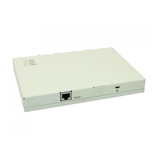
Access Point 8120 front view The following diagram illustrates the front view of the Access Point 8120. Access Point 8120 rear view The following diagram illustrates the rear view of the Access Point 8120. Avaya WLAN 8100 Installation–AP 8120 NN47251-302 01.AD... -
Page 9: Kensington Cable Interface
Solid surface wall or ceiling Attention: The solid surface mounting option requires CAT-5 cable that does not have strain relief. Other mounting options can use CAT-5 cable with or without strain relief. Avaya WLAN 8100 Installation–AP 8120 NN47251-302 01.AD 10 May 2010... -
Page 10: Status Light-Emitting Diode (Led)
10 Installation reference Status Light-emitting diode (LED) The AP 8120 has four LEDs that provide status information on the device. Refer to "Access Point 8120 front view" (page 8) for the location of the LEDs. The following table describes the different states of the LEDs. -
Page 11: Installation Preparation
If an item is missing or damaged, contact Avaya. Cabling requirements The AP 8120 access point has one RJ-45 port. This port provides a 10/100/1000BASE-TX Ethernet connection to a Wireless Controller 8180. This port is used to indirectly connect an access point to a WC 8180 through an intermediate Layer 2 or Layer 3 network. - Page 12 Failure to comply with this installation requirement can cause the device to operate in excess of the allowable emissions limits. Attention: The AP 8120 access point is intended for indoor use only. Do not install the device or operate it outdoors.
-
Page 13: Management Software
If you are using the WLAN Management Software (WMS) to plan your Avaya Mobility System installation, you can create and verify a network plan for the entire Avaya network installation and generate an AP work order, before installing any access points. -
Page 14: Radio Frequency Advisories
Spectrum Transmitters specifies a safety standard for human exposure to radio frequency electromagnetic energy emitted by FCC-certified equipment. The Avaya Access Point 8120 product meets the uncontrolled environmental limits found in OET-65 and ANSI C95.1-1991, if proper installation procedures are followed. To ensure compliance with these... -
Page 15: Access Point 8120 Installation
Perform the following procedure to mount a wireless LAN access point on a wall: Procedure steps Step Action Locate the appropriate position of the wall anchors. The wall anchors should be 95mm apart horizontally and 80mm apart vertically. Avaya WLAN 8100 Installation–AP 8120 NN47251-302 01.AD 10 May 2010... - Page 16 Tighten the screws to secure the wall mounting bracket tightly against the wall. Align the mounting tabs on the bottom of the access point sheet metal enclosure with the vertically oriented keyhole slots in the mounting bracket. Avaya WLAN 8100 Installation–AP 8120 NN47251-302 01.AD 10 May 2010...
-
Page 17: Installing An Access Point With A Ceiling Grid Adaptor
Perform the following procedure to install the access point with a ceiling grid adaptor: Avaya WLAN 8100 Installation–AP 8120 NN47251-302 01.AD... - Page 18 Securing the two brackets in this manner is essential to prevent them from disengaging from one another. Tighten the captive fastener screw securely. Avaya WLAN 8100 Installation–AP 8120 NN47251-302 01.AD 10 May 2010...
- Page 19 Make electrical connections and return ceiling tiles. --End-- Avaya WLAN 8100 Installation–AP 8120 NN47251-302 01.AD 10 May 2010...
- Page 20 20 Access Point 8120 installation Avaya WLAN 8100 Installation–AP 8120 NN47251-302 01.AD 10 May 2010...
-
Page 21: Installation Tools And Utilities
Ceiling installations Universal mounting bracket T-bar clamp Box cutter Small screwdriver (3-mm or 1/8-inch) Junction box Wall mounting Universal mounting bracket Small screwdriver (3-mm or 1/8-inch) #2 Phillips-head screwdriver Avaya WLAN 8100 Installation–AP 8120 NN47251-302 01.AD 10 May 2010... - Page 22 22 Installation tools and utilities Avaya WLAN 8100 Installation–AP 8120 NN47251-302 01.AD 10 May 2010...
-
Page 23: Access Point Troubleshooting
Do the following: • Confirm AP health using the WMS or WC 8180 CLI. • Verify that an Avaya-approv ed PoE source is supplying power to the AP. Avaya WLAN 8100 Installation–AP 8120 NN47251-302 01.AD 10 May 2010... - Page 24 WC 8180. the remedies for the other health LED appearances. If the LED still remains amber, ensure the AP is securely connected to its PoE source and to the network. Avaya WLAN 8100 Installation–AP 8120 NN47251-302 01.AD 10 May 2010...
-
Page 25: Appendix
14: Channels 1 through 14, inclusive (Japan based) 5.15 to 5.35 GHz bands IEEE mode Channel number 5.18 5.20 5.22 5.24 5.26 5.28 5.30 5.32 Frequency (GHz) 5.470 to 5.725 GHz bands IEEE mode Channel Number Avaya WLAN 8100 Installation–AP 8120 NN47251-302 01.AD 10 May 2010... -
Page 26: 5.725 To 5.85 Ghz Bands
All combinations, such as 1, 2, 7 represent all of the channels listed in the separate sections of 1, 2 and 7: 36, 40, 44, 48, 52, 56, 60, 64, 149, 153, 157, 161, 165 Avaya WLAN 8100 Installation–AP 8120 NN47251-302 01.AD... - Page 27 For example 12.5 mW = 11 dBm 11 dBm + 9dBi = 20 dBm 20 dBm = 100 mW 100mw/12.5 mW = 8 times more power Avaya WLAN 8100 Installation–AP 8120 NN47251-302 01.AD 10 May 2010...
-
Page 28: Installation–Ap
— as if looking directly at the antenna from the side. H-Plane graph The horizontal plane graph shows the radiated antenna coverage pattern as a horizontal cross section — as if looking directly at the antenna from above. Avaya WLAN 8100 Installation–AP 8120 NN47251-302 01.AD 10 May 2010...
Need help?
Do you have a question about the AP 8120 and is the answer not in the manual?
Questions and answers