Table of Contents
Advertisement
This manual is for Dake Johnson manufactured J & JH horizontal bandsaws from 1985 to
current.
If your model is prior to 1985, please contact the factory for manual and parts information.
1938 - 1965 Johnson manufactured J saws.
1965 - 1984 Kysor/Johnson manufactured J & JH saws.
PLEASE NOTE
***
****
6/02
1
Advertisement
Table of Contents

Related Manuals for Dake J-10


Summary of Contents for Dake J-10
- Page 1 6/02 PLEASE NOTE **** This manual is for Dake Johnson manufactured J & JH horizontal bandsaws from 1985 to current. If your model is prior to 1985, please contact the factory for manual and parts information. 1938 - 1965 Johnson manufactured J saws.
- Page 2 6/02 Operator’s Manual and Part’s List Model J-10 & JH-10 Dake/Johnson Horizontal Bandsaw DAKE Division of JSJ 724 Robbins Road Grand Haven, MI 49417 Phone: 1-800-937-3253 616-842-7110 Fax: 1-800-846-3253 616-842-0859 E-mail: customerservice@dakecorp.com technicalservice@dakecorp.com Web: www.dakecorp.com...
- Page 3 Please refer to the pertinent sections when contacting the factory regarding parts, schematics…or when you have other questions. As Dake’s policy is one of continuous development for each range of machine, the contents of this manual, though completely up to date when issued, are subject to change without notice.
-
Page 4: Table Of Contents
6/02 CONTENTS GENERAL Basic Machine Data ……………………………………. Specifications …………………………………………….. Machine Installation ……………………………………… Safety Information………………………………………… Electrical Diagrams ………………………………………. Machine Features ……………………………………….. SECTION 1 OPERATION Controls and Operation ………………………………….. Standard Drive …………………………………………… Blade Selection ………………………………………….. Blade Removal/Installation ……………………………… 13-14 Blade Guide Adjustment ………………………………… 14-15 Balance Spring Adjustment …………………………….. -
Page 5: Basic Machine Data
Floor Space ……………… 29” (74cm) x 70” (178com) Blade Size (Part Numbers: 75958 (3/4”) OR 75957 (1”) Height, Closed* …………………………….. 39” (99cm) J-10 ……………………… ¾” (2cm) x 137” (348cm) Height, Open* ……………………………... 64” (163cm) JH-10……………………... 1” (3cm) x 137” (348cm) Floor to Bed* …………………………….. -
Page 6: Safety Information
6/02 SAFETY INFORMATION LABEL LABEL LABEL LABEL 84604 84395 76462 84605 LABEL 84605 – SAFETY INSTRUCTIONS SAFETY This is the safety alert symbol. When you see this symbol on your saw, be alert to the potential for personal injury. Follow recommended precautions and safe operating practices. - Page 7 6/02 LABEL 84604 – SAFETY INSTRUCTIONS LABEL 84395 – DANGER LABEL LABEL 84604 – WARNING Follow recommended precautions and safe operating practices. Carefully read all safety messages in these instructions and on your saw safety signs. Keep safety labels in good condition. Replace missing or damaged safety labels.
-
Page 8: Electrical Diagrams
6/02 ELECTRICAL CONTROL DIAGRAMS... - Page 9 6/02 SINGLE PHASE ELECTRICAL DIAGRAM...
- Page 10 6/02 THREE PHASE ELECTRICAL DIAGRAM...
-
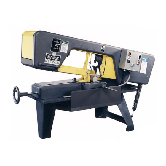
Page 11: Machine Features
6/02 MACHINE FEATURES Head Feed Blade Control Tension Handle Off-On Guide Arm Switch & Starter Balance Vise Spring Handwheel Stock Stop Gauge SECTION 1... -
Page 12: Operation
6/02 OPERATION OFF/ON SWITCH All J-saw machines are equipped with a manual starter with low voltage, dropout protection and a limit switch. When the machine frame reaches the end of its down travel it contacts the limit switch, turning off the machine. HYDRAULIC CONTROL The hydraulic control cylinder mounted on the rear of the machine is operated by a control valve mounted on the front of the machine head. -
Page 13: Standard Drive
6/02 1. Raise frame and close feed cylinder valve to hold frame in elevated position. 2. Loosen the vise nut and open the vise. Place work in vise and slide the vise swivel jaw against the work piece. Engage the vise nut and tighten the vise screw to clamp the work securely. -
Page 14: Blade Selection
6/02 BLADE SELECTION Saw blades should be selected by choosing the blade that will give the best results at the lowest cost. Type of material and the speed at which it must be sawed determine the choice. Listed below are general factors affecting blade selection. 1. - Page 15 6/02 1. Raise frame a few inches above bed and close feed cylinder valve to hold frame up. 2. Remove necessary guards and blade cleaning brushes. 3. Turn blade tension screw counterclockwise and pull idle wheel toward center of machine. 4.
-
Page 16: Blade Guide Adjustment
6/02 BLADE GUIDE ADJUSTMENT NOTE: The following instructions are for one guide arm; procedure is same for both. Left hand guide arm is shown in Figure 6. 1. Loosen nut (A, Fig. 6) and turn eccentric axle (B) until there is no light gap between rollers and blade…do not pinch the blade. -
Page 17: Maintenance
6/02 MAINTENANCE LUBRICATION Lube Instructions Point Description Interval Lubricant Drive wheel ring gear 6 months Clean thoroughly before lubricating. Gear box Maintain level Maintain level at 2 to 3 ounces. Drain and refill yearly. Capacity 3 ounces. Pivot bar (2 fittings) Monthly Use grease gun. -
Page 18: Sawing Problems And Solutions
6/02 SAWING PROBLEMS & SOLUTIONS... -
Page 19: Section 3
Section 3 6/02 ASSEMBLIES AND PARTS LIST... -
Page 20: Machine Assembly, Front View
10268-05A Right Leg Pan 10093-00 Frame Handle 10229-00 Brush holder Guard 72295 Dake/Johnson Name Plate 71541 Submersible Coolant Pump – Electric 110 volt PARTS NOT ILLUSTRATED PART NO. DESCRIPTION 10079-05 Motor, 230/460 volt, 60 Hz, 3 phase – 1 H.P. -
Page 21: Machine Assembly, Top View
Driven Pulley – 3/4" Bore (Key – Part No. 71061) 10510-01 Drive Wheel Assembly (J-10) 10010-01 Drive Wheel Only (J-10) 10052-00 Ring Gear (Used on J-10 and JH-10) 10510-03 Drive Wheel Assembly (JH-10) 10010-03 Drive Wheel Only (JH-10) 10062-00 Wheel Axle (J-10 & JH-10) 10134-01 Bearing Cup (J-10 &... -
Page 22: Gearbox Assembly
6/02 GEARBOX ASSEMBLY ITEM PART NO. DESCRIPTION 10544-00 Gear Case Assembly Complete 5047-00 Bearing Cap 5138-00 Cap Gasket 5073-00 Bearing 5044-00 Gear Case 5142-00 Dowel Pin 5072-00 Bearing 10049-00 Worm Gear Shaft 8 & 15 10051-51 Worm – Steel Worm & Gear Bronze Assembly (10051-00 & 10050-00) 13080-01 Cover Gasket 5045-00... -
Page 23: Hydraulic Assembly
6/02 HYDRAULIC ASSEMBLY... - Page 24 6/02 ITEM PART NO. DESCRIPTION 10530-10 Hydraulic Assembly (Includes Control Valve Assembly) 10530-09 Cylinder Assembly (Only) 10031-00 Cylinder Base 10203-03 Fiber Seal 10205-02 Tie Rod 5129-00 Spring 5116-00 Spring – R Style included in repair kit. 17817 3/8 inch Ball 10204-02 Piston Rod 10033-00...
-
Page 25: Guide Arm Assembly
6/02 GUIDE ARM ASSEMBLY T-slot Dimension 5/8” New Style ITEM PART NO. DESCRIPTION 10519-10 Guide Arm Assembly Complete LH & RH 10019-10 Guide Arm LH & RH 10020-10 Guide Holder 10084-01 Guide Arm Tightening Handle 10025-01 Side Guide Bearing 5026-00 Upper Guide Bearing 5023-01 Upper Guide Bushing... -
Page 26: Vise Unit
6/02 VISE UNIT ITEM PART NO. DESCRIPTION 10007-00 Hold Down Block 10099-00 Vise Lift 5200-00 Handle 10008-00 Movable Vise Jaw (Bolt – Part No. 43348) 10009-00 Stationary Vise Jaw (Bolt – Part No. 43348) 10116-00 Lift Pin 10201-00 Vise Nut Plate (Self Tapping Screw (10-24) – Part No. 43882) 10016-00 Vise Nut 10015-10... - Page 27 Horizonal Bandsaws, Vertical Bandsaws and Cold Saws A complete line of Arbor, H-Frame and custom engineered competitively priced. Hydraulic Presses for production, maintenance and research work. DAKE Division of JSJ 724 Robbins Road Grand Haven, MI 49417 Phone: 1-800-937-3253 616-842-7110...
Need help?
Do you have a question about the J-10 and is the answer not in the manual?
Questions and answers