Table of Contents
Advertisement
FOR MODELS
E-16
V-16
V-24
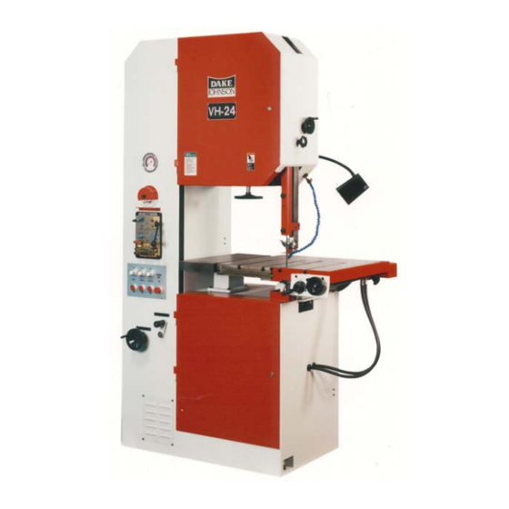
VH-24
V-40
VH-40
MODEL: ________________________________________
SERIAL NUMBER: ________________________________
N MANUAL AND PARTS LIST
DATE PURCHASED: ______________________________
Manual V-16, V-24, VH-24, V-40 & VH-40
JOHNSON VERTICAL BAND SAWS
INSTRUCTION MANUAL AND PARTS LIST
SECTION I – Manual
DAKE Division of JSJ
724 Robbins Road
Grand Haven, Michigan 49417
616.842.7110
Phone 800-937-3253
616.842.0859
Fax 800-846-3253
Web:
www.dakecorp.com
E-mail :
customerservice@dakecorp.com
technicalsupport@dakecorp.com
1 – Section I
4/29/03
Advertisement
Table of Contents

Related Manuals for Dake E-16


Summary of Contents for Dake E-16
- Page 1 INSTRUCTION MANUAL AND PARTS LIST SECTION I – Manual FOR MODELS E-16 V-16 V-24 VH-24 V-40 VH-40 DAKE Division of JSJ 724 Robbins Road Grand Haven, Michigan 49417 MODEL: ________________________________________ 616.842.7110 Phone 800-937-3253 616.842.0859 Fax 800-846-3253 SERIAL NUMBER: ________________________________ Web: www.dakecorp.com...
- Page 2 4/29/03 If machine is to be operated At 440 volt 3 phase power, please read the following warning. WARNING! This machine must be wired by a qualified electrician. Do not connect 440-volt power directly to this machine. The use of the step down transformer supplied with this machine must be used.
-
Page 3: Table Of Contents
4/29/03 SECTION I - TABLE OF CONTENTS Specifications ..................Machine Features ................Unloading ..................... Installation .................... Electrical ....................Filling Speed Regulator ………………………………………………….. Machine Operation ................Wheel Alignment ................. Blade Installation ................. Blade Tensioning ................Blade Guides / Adjustment ..............10-14 Band Speed Selection ................. -
Page 4: Specifications
4/29/03 SPECIFICATIONS Model Number: V-16 V-24/VH-24 V-40/VH-40 Capacity: Throat Inches 23-1/2 Work Height Inches 12-1/2 12-1/2 Table: Work Table Inches 23-1/2 x 23-1/2 26-3/8 x 26-3/8 26-3/8 x 26-3/8 Auxiliary Inches 9 x 22-3/8 15-1/2 x 21-1/2 Height from Floor Inches Travel-Manual or Hydraulic Inches... -
Page 5: Machine Features
4/29/03 5 – Section I Manual V-16, V-24, VH-24, V-40 & VH-40... - Page 6 4/29/03 6 – Section I Manual V-16, V-24, VH-24, V-40 & VH-40...
-
Page 7: Unloading
The machine is wired to be operated with an input voltage of 230, 3 phase, 60 htz (+/- 10%) or with a Dake external step down transformer from 460v to 230v. If any adjustments or changes are needed a qualified electrician should perform them. See detailed information as provided in a circuit diagram #80587. -
Page 8: Filling Speed Regulator
4/29/03 FILLING THE SPEED REGULATOR Turn the saw on. Screw the handwheel in. Turn the saw off once handwheel is in. Remove the mounting screws (item 6). Remove the plug from the cylinder (Item 3). Turn screw out. Add oil (Lightweight hydraulic oil) slowly while turning the wheel out. When it is completely full, replace the plug (Item 3). -
Page 9: Wheel Alignment
4/29/03 WHEEL ALIGNMENT V-16 & V / VH-24 Note: This alignment is factory set, but may need adjustment when replacing blade. Two wheel machines have a bottom wheel that drives the saw blade and a top idle wheel that is adjustable to facilitate blade tracking. -
Page 10: Blade Tensioning
4/29/03 BLADE TENSIONING The blade indicator is located inside the upper wheel compartment, on the lower left side of the idle wheel. (See machine features graphic) The indicator has an arrow mounted on the horizontal plane, with a corresponding scale for blade tensioning. The scale has two legends, one reads inches from 0 - 1”, the second reads mm 0 - 25 mm. - Page 11 4/29/03 An analysis of the work to be performed should be made and the proper blade selected. The blade should always be inspected before installing on the machine. Things to look for should be the smoothness on the sides and back edge of the weld, look for any missing teeth, or impacted chips.
- Page 12 4/29/03 HIGH SPEED ROLLER GUIDES Applications and Advantages: Friction and abrasive cutting, filing operations, aluminum and woodcutting. These guides eliminate having to change inserts when changing to blades of different widths. Requirements for Installation: These roller guides must be installed using a new 1/2” blade width band for proper alignment. The 1/2”...
- Page 13 4/29/03 4: Insert the mounting stud (B) into the guide casting (A). Keep the stud flush with the front of the casting. Keeping the mounting stud flat area on the bottom, tighten securely the set screw (C) on the bottom of the casting.
-
Page 14: Band Speed Selection
4/29/03 Repeat this process for the lower guide assembly. Note: Upper guide stud may be adjusted in or out in the guide post to allow proper clearance for blade, and for alignment with lower guide. Align backup bearing as previously described for upper guide. Tighten both set screws when alignment is confirmed. -
Page 15: Saw Blade Selection
4/29/03 Note: Occasionally the drive wheel may have to be jogged by hand to engage the transmission lever. The variable speed is achieved through the use of a variable regulator. (Figure 3) This is turned clockwise or counter clockwise to obtain an increase or decrease in blade speed, in either range. -
Page 16: Speeds & Feeds
4/29/03 SAW BLADE SELECTION MATERIAL SHAPE MATERIAL SHAPE MATERIAL SHAPE MATERIAL IN INCHES TOOTH SELECTION TOOTH SELECTION TOOTH SELECTION 14 / 18 14 / 18 14 / 18 14 / 18 14 / 18 14 / 18 14 / 18 14 / 18 14 / 18 10 / 14... - Page 17 4/29/03 MATERIAL ALLOY 1/2" 1" 2" 4" 7" 12" 1100,2011,2017,2024 fpm 568 sipm 7 fpm 577 sipm 11 fpm 536 sipm 16 fpm 498 sipm 21 fpm 451sipm 23 fpm 389 sipm 24 ALUMINUM ALLOY 3003,5052,5086,6061 fpm 568 sipm 7 fpm 577 sipm 11 fpm 536 sipm 16 fpm 498 sipm 21...
- Page 18 4/29/03 MATERIAL ALLOY 1/2" 1" 2" 4" 7" 12" fpm 227 sipm 3 fpm 223 sipm 4 fpm 214 sipm 6 fpm 199 sipm 9 fpm 180 sipm 9 fpm 156 sipm 10 COLD-WORK fpm 204 sipm 3 fpm 200 sipm 4 fpm 193 sipm 6 fpm 179 sipm 8 fpm 162 sipm 8...
- Page 19 4/29/03 NITRONIC 50,60 fpm 68 sipm 1 fpm 67 sipm 1 fpm 64 sipm 2 fpm 60 sipm 3 fpm 54 sipm 3 fpm 47 sipm 3 MATERIAL ALLOY 1/2" 1" 2" 4" 7" 12" MARTENSITIC STAINLESS STEEL GREEK ASCOLOY fpm 108 sipm 1 fpm 106 sipm 2 fpm 102 sipm 3...
-
Page 20: Rate Reduction Matrix For Hard Material
4/29/03 MATERIAL ALLOY 1/2" 1" 2" 4" 7" 12" INCONEL 751,X750 fpm 79 sipm 1 fpm 79 sipm 1 fpm 79 sipm 1 fpm 79 sipm 1 fpm 79 sipm 1 fpm 79 sipm 1 NICKEL BASE WASPALOY fpm 79 sipm 1 fpm 79 sipm 1 fpm 79 sipm 1 fpm 79 sipm 1... -
Page 21: Hydraulic Feed Table
Note: Always wear eye protection when using this welder or grinder! Your Dake vertical band saw is equipped with a “resistance-type” butt welder. The two clamp jaws of the welder hold the blade ends together. When the welding start knob is turned fully clockwise past the zero setting, electric current flows through the blade ends creating enough heat to soften and join them. -
Page 22: Clamping / Welding / Annealing
4/29/03 Cut the blade ends accurately and at right angles. (See graphic below) Check abutment against the stop for a cut at right angles. Proper welding can only be achieved if the blade ends are cut with out a burr and at right angles. (Also see trouble shooting section) 2. -
Page 23: Re-Finishing The Weld (Grinding)
4/29/03 After welding loosen the pressure clamps (7 fig. 1) and set the jaws to the wide annealing position by turning the upsetting pressure switch (2 fig. 1) counter clockwise. Re-clamp the blade so that the weld is in the center between the jaws. Operate the annealing switch (8 fig.1) until the weld becomes dark cherry red. -
Page 24: Machine Maintenance
If the welder does not shut off, after the welding cycle, or will not start the welding cycle, a limit switch adjustment is needed. THE WELDER MUST BE REMOVED FOR THIS ADJUSTMENT. SHOCK HAZARD! ALWAYS CONTACT DAKE BEFORE REMOVING THE WELDER OF MAKING INTERNAL ADJUSTMENTS. A QUALIFIED ELECTRICIAN MUST DO THESE ADJUSTMENT. MACHINE MAINTENANCE The maintenance of the machine is naturally based on the usage rather than a time element. - Page 25 4/29/03 RIP FENCE Standard all models (figure 2) (Part number 714805 – Model 24/40) (Part number 714869 – Model 16) Used for cutting material in accurate straight lines. To attach, insert T-bolt provided in the T-slot in the front of the table. Slide into the desired position and tighten handle.
Need help?
Do you have a question about the E-16 and is the answer not in the manual?
Questions and answers