
Related Manuals for Dake F-16


Summary of Contents for Dake F-16
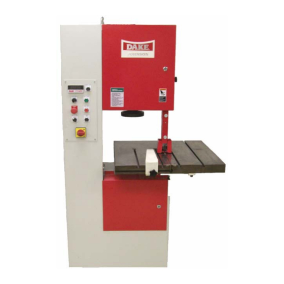
- Page 1 DAKE / JOHNSON VERTICAL BAND SAW Model F - 16 INSTRUCTION MANUAL MODEL:F-16________________________ SERIAL NUMBER:___________________ DATE PURCHASED: _________________ 4/11/2007...
-
Page 2: Specifications
WARNING! This machine must be wired by a qualified electrician. This machine is designed to be wired for the specified voltage with a tolerance of +/- 10%. If your voltage is outside this 10% it will require a transformer to obtain the correct voltage. -
Page 3: Installation
Machine Features F - 16 WARNING!!! The machine table must NOT be used as a lifting point. Damage to the saw could occur. UNLOADING: Remove the shrink-wrap covering the machine, careful not to damage painted surfaces. Carefully inspect the machine for physical damage. If damage is noted, notify the truck line at once. - Page 4 These surfaces should be cleaned with the appropriate solvent and then coated with a light film of oil to prevent rust from forming. F-16 Foot Print Below measurement is in inches 23.6 17.7 14.9 3.93...
- Page 5 ELECTRICAL: To wire this machine there is a small box on the back side of the machine, this is where the machine is wired in (see illustration below). warning!!! Power must be locked out before removing any electrical panel. WARNING! This machine must be wired by a qualified electrician.
-
Page 6: Blade Installation
440 Volt 3 Phase To use 440 volt on this machine a step down transformer is required. Dake part number 300674 Prior to performing any cutting with the machine, it is recommended that the personal become familiar with the various controls and accessories. -
Page 7: Blade Tracking
WARNING!!! Electrical supply must be locked out when changing the blade. Blade selection is based on the many factors and complexity of the work to be cut. The blade placed on the band wheels with teeth facing toward the operator and down toward the top of the worktable. -
Page 8: Blade Tensioning
BLADE TENSIONING The blade indicator is located inside the upper wheel compartment, on the lower left side of the idle wheel. (See picture above) The indicator has an arrow mounted on the horizontal plane, with a corresponding scale for blade tensioning. The scale has two legends, one reads inches from 0 - 1”, and the second reads mm 0 - 25 mm. -
Page 9: Blade Guides
The blade should always be inspected before installing on the machine. Things to look for should be the smoothness on the sides and back edge of the weld, look for any missing teeth, or impacted chips. The blade guides may now be selected and inserted into both the upper and lower guide holders. - Page 10 MATERIAL SHAPE MATERIAL SHAPE MATERIAL SHAPE MATERIAL IN INCHES TOOTH SELECTION TOOTH SELECTION TOOTH SELECTION 14 / 18 14 / 18 14 / 18 14 / 18 14 / 18 14 / 18 14 / 18 14 / 18 14 / 18 10 / 14 14 / 18 10 / 14...
- Page 11 Machine Operation Look over the control panel to get familiar with the buttons before operating (see picture below). Power Start Digital Tach read out Saw Start Blade Speed Emergency Stop Saw Stop Run / Jog Main Power Switch Digital Tachometer Read out: This will show the blade speed in surface feet per minute. Blade Speed: This controls the speed of the blade 50-550 sfm.
-
Page 12: Machine Operation
MACHINE OPERATION To operate the machine, do the following: 1. Turn the main power on, and then push the saw power button. 2. Now turn the run jog button to run, and then push the saw start button. The saw blade will begin to move at the designated speed that is selected. - Page 13 ACCESSORIES Rip Fence Part number 81521 PROTRACTOR HEAD See figure 4 part number 75561 T-SLOTS T-slots are machined into the work table for your use of fixturing or other accessories. The dimensions of these T-slots are furnished to the right. How to program the frequency drive.
- Page 14 How to program the digital speed display (This is factory set and will only need to be programmed if the unit is replaced) 1. Press and hold the set button (top left corner) until the display shows Fun 2. Push the set button one time, the display will read rPS . If the display does not show rPS then push the “RST”...
-
Page 15: Parts Breakdown And Parts List
PARTS BREAKDOWN AND PARTS LIST 4/11/2007... - Page 16 Figure 1.1 ITEM PART NAME PART NO. F-16 Hand wheel 81529 Adjusting Wheel Collar 81530 Spindle 81532 Crown Spring 81534 Axial Bearing 81536 Spacer 81538 Lath Gib 81540 Carriage 81542 Carriage Lower Portion 81544 Rack 81546 Screw 4mm x 16mm...
- Page 17 Tracking band wheel assembly 1.2 Figure 1.2 ITEM PART NAME PART NO. Complete Assembly 716501 Screw 8mm x 10mm 81571 Jam nut 8mm 91573 Set Screw 8mm x 25mm 81574 Nylon Bandage (80540) 714834 Upper Band Wheel 80618 Cap Screw 8mm x 25 mm 81575 Flange 80650...
- Page 18 Figure 2.1 ITEM PART NAME PART NO. V/E-16 Table Insert (Left Rear) 81597 Table Insert (Right Rear) 81598 Table Insert 81792 Table Casting 81700 Cap Screw 4mm x 12 mm 81701 Adaptor Plate 301843 Table Bolts M10 1.5 x 25mm 78758 Frame Bolts M10 1.5 x 50mm 78729...
- Page 19 Lower Wheel assembly 3.7 ITEM PART NAME PART NO. V/E-16 Band Wheel Cover – Sold as 714834x 80540 Band Wheel Casting 80618 Set Screw 81863 Flange 81865 Washer 5/16” x 1/16” thick 43632 Cap Screw 8mm x 25mm 81575 Complete Wheel Assembly 714834X Not shown Wheel magnet...
- Page 20 Blade guard assembly 4.6 Blade guard assembly 4.6 Item Part # Part Description Qty. 81926 Brush bolt 81924 Wood screw 81526 Knurled thumb screw 81929 Chip guard 81930 Brush holder 81931 Wire chip brush 81932 Upper blade cover 81933 Alignment screws 81934 Blade guard body 80625...
-
Page 21: Blade Guide Assembly
Blade Guide Assembly 4.8 Item # Part Name Part # Qty. Cap Screw 81781 Blade Guide Holder 81935 Set Screw 81936 4/7/8 Rear Bearing Guide Assembly 80586 Washer 81938 Cap Screw 64179 Cap Screw 80521 Washer 43632 Cap Screw 81707 Lower Guide Mounting Plate 81941 13/14... - Page 22 PART Item # PART NAME Gear box 301663 Motor Single Phase and 3 phase 301665 Digital read out 301832 Blade Speed Dial 301666 Emergency Stop Button 716538 Run / Jog Switch 716544 Main Power switch w / motor protection 301781 Power Start Button 716542 Saw Start Button...
- Page 23 Items not shown on gear box assembly Washer 70270 Bolt 81505 Shaft 87121 Bearing 301810 Outboard Support 87131 8mm x 35mm 301811 8mm x 65mm 301812 81851 Key ¼ x ¼ x 4” 301818 Door Handle 301779 Shaft Extension 301780 Fuse 2 amp 72633 Fuse 5 amp...
- Page 24 4/11/2007...
Need help?
Do you have a question about the F-16 and is the answer not in the manual?
Questions and answers