Table of Contents
Advertisement
Quick Links
Download this manual
See also:
Workshop Manual
Perkins 700 Series
Introduction.
Whilst you are in this page, you have the choice of either navigating to
the Users Handbook or the Workshop Manual, by simply selecting the
title of your choice.
05/99
Printed in England
© Propriety information of Perkins Engines Company Limited, all rights reserved
Interactive CD
Users Handbook
Workshop Manual
700 Series
Advertisement
Chapters
Table of Contents

Related Manuals for Perkins 700 Series


Summary of Contents for Perkins 700 Series
- Page 1 Whilst you are in this page, you have the choice of either navigating to the Users Handbook or the Workshop Manual, by simply selecting the title of your choice. Users Handbook Workshop Manual 05/99 Printed in England © Propriety information of Perkins Engines Company Limited, all rights reserved...
-
Page 2: How To Use This Manual
(preventive maintenance) or repairing the engine, it does not contravene the local regulations when in use. The information is correct at time of print. Published in May 1999 by Technical Publications, Hawtal Whiting Engineering Ltd. 05/99 Printed in England © Propriety information of Perkins Engines Company Limited, all rights reserved... -
Page 3: General Information
More than sixty years of diesel production experience, together with the latest technology, have been applied to the manufacture of your engine to give you reliable and economic power. 05/99 Printed in England © Propriety information of Perkins Engines Company Limited, all rights reserved... -
Page 4: Table Of Contents
How to set the valve tip clearances … … … … … … … … … … … … … … … … … … … 31 05/99 Printed in England © Propriety information of Perkins Engines Company Limited, all rights reserved... -
Page 5: Contents
Engine … … … … … … … … … … … … … … … … … … … … … … … … … … … … … … 42 05/99 Printed in England © Propriety information of Perkins Engines Company Limited, all rights reserved... -
Page 6: How To Care For Your Engine
Warning! Read the "Safety precautions" and remember them. They are given for your protection and must be applied at all times. 05/99 Printed in England © Propriety information of Perkins Engines Company Limited, all rights reserved... -
Page 7: Safety Precautions
(especially when the batteries are on charge) because the gases from the electrolyte are highly flammable. The battery fluid is dangerous to the skin and especially to the eyes. 05/99 Printed in England © Propriety information of Perkins Engines Company Limited, all rights reserved... -
Page 8: Engine Identification
Engine serial number Year of manufacture If you need parts, service or information for your engine, you must give the complete engine number to your Perkins distributor. 05/99 Printed in England © Propriety information of Perkins Engines Company Limited, all rights reserved... -
Page 9: Perkins Companies
Fax: 0081 (0) 3 582 1596 Singapore Perkins Engines (Far East) pte Ltd Tuas Avenue 13 Singapore 638999 Telephone: (65) 861 1318 Fax: (65) 861 6252 05/99 Printed in England © Propriety information of Perkins Engines Company Limited, all rights reserved... -
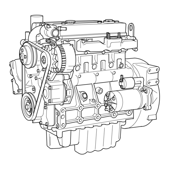
Page 10: Engine Views Introduction
Engine Views Engine views Introduction Perkins engines are built for specific applications and the views which follow do not necessarily match your engine specification. Location of engine parts Front and left side view of a UA or a UB engine (A) - Page 11 28 Speed control 21 Flywheel 29 Lubricating oil dipstick 22 Canister for the lubricating oil filter 30 Fuel lift pump 31 Sump for the engine lubricating oil 05/99 Printed in England © Propriety information of Perkins Engines Company Limited, all rights reserved...
- Page 12 12 Filler cap for the lubricating oil 5 Coolant pump pulley 13 Starter motor 6 Alternator 14 Drain plug for the lubricating oil 7 Drive belt 8 Crankshaft pulley 05/99 Printed in England © Propriety information of Perkins Engines Company Limited, all rights reserved...
- Page 13 28 Lubricating oil cooler 20 Lubricating oil dipstick 29 Lubricating oil filter canister 21 Flywheel housing 30 Fuel filter canister 22 Flywheel 23 Lubricating oil sump 05/99 Printed in England © Propriety information of Perkins Engines Company Limited, all rights reserved...
-
Page 14: Operation Instructions
3 Fill the fuel tank with fuel of the correct specification. 4 Check the air filter and its connections. 5 Ensure that all of the electrical connections are tight. 05/99 Printed in England © Propriety information of Perkins Engines Company Limited, all rights reserved... -
Page 15: How To Start A Cold Engine In Cold Conditions
"R" position (B). As the engine speed begins to increase, quickly reduce the engine speed. At this point, the glow plugs will continue to operate for a short period of time. 05/99 Printed in England © Propriety information of Perkins Engines Company Limited, all rights reserved... -
Page 16: How To Start A Cold Engine In Temperate Conditions
This will allow heat from the large ferrous components to pass into the lubricating oil and the engine coolant. Move the engine start key to the "OFF" position. 05/99 Printed in England © Propriety information of Perkins Engines Company Limited, all rights reserved... -
Page 17: Adjustment Of Engine Speed Range
60 C (140 The engine will benefit if the load is applied as soon as possible after the engine is put into service. 05/99 Printed in England © Propriety information of Perkins Engines Company Limited, all rights reserved... -
Page 18: Preventive Maintenance
These maintenance periods apply only to engines that are operated with fuel and lubricating oil which conform to the specifications given in this handbook. 05/99 Printed in England © Propriety information of Perkins Engines Company Limited, all rights reserved... -
Page 19: Schedules
Specification in section 5). The interval to change the canister of the lubricating oil filter is not affected. UC engines: Renew the engine breather valve every 5000 hours (2). Refer to the workshop manual. 05/99 Printed in England © Propriety information of Perkins Engines Company Limited, all rights reserved... -
Page 20: How To Drain The Cooling System
5 Flush the system with POWERPART Easy Flush. 6 Fit the drain plugs and the filler cap. Close the radiator tap or connect the radiator hose. 05/99 Printed in England © Propriety information of Perkins Engines Company Limited, all rights reserved... -
Page 21: How To Check The Specific Gravity Of The Coolant
-35 C (-31 F). It will also give protection against corrosion. This is especially important when there are aluminium components in the coolant circuit. 05/99 Printed in England © Propriety information of Perkins Engines Company Limited, all rights reserved... -
Page 22: How To Check The Drive Belt
3 Check the belt tension again to ensure that it is still correct. If a new belt is fitted, the belt tension must be checked again after the first 25 hours of operation. 05/99 Printed in England © Propriety information of Perkins Engines Company Limited, all rights reserved... -
Page 23: How To Renew The Element / Canister Of The Fuel Filter
12 Eliminate the air from the fuel filter, see page 26. 05/99 Printed in England © Propriety information of Perkins Engines Company Limited, all rights reserved... -
Page 24: Atomiser Fault
3 Remove the union nuts of the high-pressure pipe from the atomiser and from the fuel injection pump. Do not bend the pipe. If necessary, remove the pipe clamps. 05/99 Printed in England © Propriety information of Perkins Engines Company Limited, all rights reserved... -
Page 25: How To Renew An Atomiser - Ub Engines
5 Clean thoroughly the threads on the body of the atomiser and fit plastic caps to the atomiser. Continued 05/99 Printed in England © Propriety information of Perkins Engines Company Limited, all rights reserved... - Page 26 27 Nm (20 lbf ft) 2,8 kgf m. Fit the pipe clamps. 10 Eliminate air from the fuel system, see page 26. 11 Operate the engine and check for leakage of fuel and air. 05/99 Printed in England © Propriety information of Perkins Engines Company Limited, all rights reserved...
-
Page 27: How To Eliminate Air From The Fuel System
Stop the engine and turn the start key to the "OFF" position. Check for air leaks. 05/99 Printed in England © Propriety information of Perkins Engines Company Limited, all rights reserved... -
Page 28: How To Renew The Lubricating Oil
8 Start the engine and check for lubricating oil leakage. Stop the engine. After 15 minutes check the oil level on the dipstick and, if necessary, put more lubricating oil into the sump. 05/99 Printed in England © Propriety information of Perkins Engines Company Limited, all rights reserved... -
Page 29: How To Renew The Canister Of The Lubricating Oil Filter
Caution: Do not fill the sump past the "FULL" mark on the dipstick, see "Caution" on page 27. 05/99 Printed in England © Propriety information of Perkins Engines Company Limited, all rights reserved... -
Page 30: How To Renew The Engine Breather Assembly - Ua & Ub Engines
10 Fit the rocker cover and tighten the cap nuts to 11 Nm (8 lbf ft) 1,1 kgf m. Note: For UC engines refer to the workshop manual, publication number TPD 1392E issue 1. 05/99 Printed in England © Propriety information of Perkins Engines Company Limited, all rights reserved... - Page 31 The filter element must be cleaned or renewed according to the manufacturer's recommendations. 05/99 Printed in England © Propriety information of Perkins Engines Company Limited, all rights reserved...
-
Page 32: How To Set The Valve Tip Clearances
(B5) has just opened and the valve (B6) has not closed completely. Check the clearances of the valves (B3) and (B4) and adjust them, if necessary. Continued 05/99 Printed in England © Propriety information of Perkins Engines Company Limited, all rights reserved... - Page 33 9 For turbocharged engines: remove the covers from the turbocharger and the induction manifold. Fit the pipe between the turbocharger and the induction manifold and tighten the hose clips. 05/99 Printed in England © Propriety information of Perkins Engines Company Limited, all rights reserved...
-
Page 34: Engine Fluids
Perkins Distributor or one of the companies listed on page 8. 05/99 Printed in England © Propriety information of Perkins Engines Company Limited, all rights reserved... -
Page 35: Lubricating Oil Specification
A = Recommended viscosity range in which the engine will run as shown in the B = Ambient temperature chart (A). 05/99 Printed in England © Propriety information of Perkins Engines Company Limited, all rights reserved... -
Page 36: Coolant Specification
Concentrations of more than 50% of antifreeze may have an adverse effect on the performance of the coolant. 05/99 Printed in England © Propriety information of Perkins Engines Company Limited, all rights reserved... -
Page 37: Fault Diagnosis
39, 42, 44, 45, 52, 61 37, 39, 40, 42, 43, 44, 45, Bad compression 11, 22 53, 60 The engine starts and stops 10, 11, 12 05/99 Printed in England © Propriety information of Perkins Engines Company Limited, all rights reserved... -
Page 38: List Of Possible Causes
33 Vacuum pipe leak or fault in exhauster. 34 Fault in fuel injection pump. 35 Broken drive on fuel injection pump. 36 Timing of fuel injection pump incorrect. 05/99 Printed in England © Propriety information of Perkins Engines Company Limited, all rights reserved... -
Page 39: Engine Preservation
Department, Perkins Engines Company Limited, Peterborough. 7 Operate the engine for a short period in order to circulate the lubricating oil and the coolant in the engine. 05/99 Printed in England © Propriety information of Perkins Engines Company Limited, all rights reserved... - Page 40 Perkins are not responsible for damage which may occur when an engine is in storage after a period in service. 05/99 Printed in England © Propriety information of Perkins Engines Company Limited, all rights reserved...
-
Page 41: Parts And Service
POWERPART Platelock head. Part number 21825474 Medium strength anaerobic threadlock for tight fitted metal surfaces. Suitable for metal plated surfaces and stainless steel. Part number 21826039. 05/99 Printed in England © Propriety information of Perkins Engines Company Limited, all rights reserved... - Page 42 Part number 21820542 POWERPART Threadlock (pipe) To retain and seal pipe connections with coarse threads. Pressure systems can be used immediately. Part number 21820575. 05/99 Printed in England © Propriety information of Perkins Engines Company Limited, all rights reserved...
-
Page 43: General Data
(1) The capacity of the sump may vary according to the application. Fill to the "Full" mark on the dipstick. Do not exceed the "Full" mark, see page 27 for cautions. 05/99 Printed in England © Propriety information of Perkins Engines Company Limited, all rights reserved... - Page 44 700 Series Perkins 700 Series Interactive CD Do you wish to quit..The User's Handbook? Exit this CD-ROM? 05/99 Printed in England © Propriety information of Perkins Engines Company Limited, all rights reserved...
- Page 45 (preventive maintenance) or repairing the engine, it does not contravene the local regulations when in use. The information is correct at time of print. Published in May 1999 by Technical Publications, Hawtal Whiting Engineering Ltd. 05/99 Printed in England © Propriety information of Perkins Engines Company Limited, all rights reserved...
- Page 46 FOREWORD This manual is illustration based and the usual Perkins sections of 10 to 25 have been used. The aim of the manual is to provide the trained technician with enough information to service and overhaul all of the Perkins 700 Series engines.
- Page 47 Caution: This indicates that there is a possible danger to the engine. Note: Is used where the information is important, but there is not a danger. 05/99 Printed in England © Propriety information of Perkins Engines Company Limited, all rights reserved...
- Page 48 Cylinder Head - to check the distortion of the lower face … … … … … … … … … … … … … 51 Continued 05/99 Printed in England © Propriety information of Perkins Engines Company Limited, all rights reserved...
- Page 49 Backplate for the timing case -to remove and to fit… … … … … … … … … … … … … … … 90 Continued 05/99 Printed in England © Propriety information of Perkins Engines Company Limited, all rights reserved...
- Page 50 To record the maximum fuel position of the fuel control rack … … … … … … … … … … 127 How to use the reference setting for maximium fuel … … … … … … … … … … … … … 132 Continued 05/99 Printed in England © Propriety information of Perkins Engines Company Limited, all rights reserved...
- Page 51 List of special tools … … … … … … … … … … … … … … … … … … … … … … … … … 152 05/99 Printed in England © Propriety information of Perkins Engines Company Limited, all rights reserved...
-
Page 52: General Information
Fit safety wires to secure the plugs which seal the hose connections of a component which is to be pressure tested. • Do not allow compressed air to contact your skin. If compressed air enters your skin, obtain medical help immediately. Continued 05/99 Printed in England © Propriety information of Perkins Engines Company Limited, all rights reserved... - Page 53 Use lift equipment or obtain assistance to lift heavy engine components such as the cylinder block, the cylinder head, the flywheel housing, the crankshaft and the flywheel. 05/99 Printed in England © Propriety information of Perkins Engines Company Limited, all rights reserved...
-
Page 54: Viton Seals
If there is contamination of the skin or eyes wash the affected area with a continuous supply of clean water or with calcium hydroxide solution for 15 - 60 minutes. Obtain immediate medical attention. 05/99 Printed in England © Propriety information of Perkins Engines Company Limited, all rights reserved... - Page 55 These products are available and are recommended to assist in the correct operation, service and maintenance of your engine and your machine. The instructions for the use of each product are given on the outside of each container. These products are available from your Perkins distributor. Antifreeze Protects the cooling system against frost and corrosion 1 litre.
- Page 56 Currently Loctite 542. Part number 21820524 Threadlock (pipe) To retain and seal pipe connections with coarse threads. Pressure systems can be used immediately. Currently Loctite 575. Part number 21820575 05/99 Printed in England © Propriety information of Perkins Engines Company Limited, all rights reserved...
-
Page 57: Engine Identification
A = 1995 B = 1996 C = 1997 D = 1998 E = 1/1/1999 - 31/3/1999 F = 1/4/1999 - 31/12/1999 G = 2000 05/99 Printed in England © Propriety information of Perkins Engines Company Limited, all rights reserved... -
Page 58: Engine Views
Section 10 700 Series General Information Operation: Engine views - naturally aspirated engine 05/99 Printed in England © Propriety information of Perkins Engines Company Limited, all rights reserved... - Page 59 Section 10 700 Series General Information Operation: Engine views - turbocharged engine 05/99 Printed in England © Propriety information of Perkins Engines Company Limited, all rights reserved...
-
Page 60: Compression Test Data
4 Disconnect the stop solenoid or put the stop control in the no-fuel position. Operate the starter motor and note the maximum pressure indicated on the gauge. 5 Repeat for each cylinder. 05/99 Printed in England © Propriety information of Perkins Engines Company Limited, all rights reserved... -
Page 61: Specifications
Typical dry installed engine weight (2) … … … … … … … … … … … … … … … 200 kg (440 lb) (1) Minimum pressure at maximum engine speed and normal engine temperature (2) Engine weight may alter with final specification. 05/99 Printed in England © Propriety information of Perkins Engines Company Limited, all rights reserved... -
Page 62: Recommended Torque Tensions
Crankshaft assembly Setscrews, main bearings 15,0 Setscrews, pulley/ damper assembly 18,9 Cylinder block Piston cooling valve, UC engines 3/8 UNF Breather deflector, UC engines 05/99 Printed in England © Propriety information of Perkins Engines Company Limited, all rights reserved... - Page 63 Angleichung unit to timing case Turbocharger Nut, turbocharger oil drain 7/8 UNS Nut, turbocharger oil feed 7/16 UNS Electrical Glowplug Connection, glow plug 1,15 0,12 05/99 Printed in England © Propriety information of Perkins Engines Company Limited, all rights reserved...
-
Page 64: Data And Dimensions
0.185 3,17 0.125 Timing shims Part number Thickness mm (in) 3621F011 0,1 (0.004) 3621F012 0,2 (0.008) 3621F013 0,3 (0.012) 3621F014 0,4 (0.016) 3621F015 0,5 (0.020) 05/99 Printed in England © Propriety information of Perkins Engines Company Limited, all rights reserved... - Page 65 … … … … … … … … … … … … … … … 91,500/91,525 mm (3.6024/3.6033 in) Final surface finish grade, silicon carbide (plateau hone) … … … … … … … … 0,65/1,3 micro-meters Continued 05/99 Printed in England © Propriety information of Perkins Engines Company Limited, all rights reserved...
- Page 66 UB ENGINES 0,010 TYPICAL 0,020 0,03 /100 Y- Z UA AND UC ENGINES x 45˚TYPICAL 97,525 Ø TYPICAL 0,010 97,500 0,020 0,03 /100 Y- Z 05/99 Printed in England © Propriety information of Perkins Engines Company Limited, all rights reserved...
- Page 67 Angle of valve face … … … … … … … … … … … … … … … … … … … … … … … … … … … 45° Continued 05/99 Printed in England © Propriety information of Perkins Engines Company Limited, all rights reserved...
- Page 68 Valve tip clearances (cold) … … … … … … … … … … … … … … … … … … … 0,35 mm (0.014 in) Continued 05/99 Printed in England © Propriety information of Perkins Engines Company Limited, all rights reserved...
- Page 69 B3......38,7/38,9 mm (1.52/1.53 in) B4....35,125/35,150 mm (1.3828/1.3838 in) B5......8,2/8,4 mm (0.32/0.33 in) 05/99 Printed in England © Propriety information of Perkins Engines Company Limited, all rights reserved...
- Page 70 A9 ........1,5 mm (0.06 in) A10 ..... 6,95/6,97 mm (0.273/0.274 in) 05/99 Printed in England © Propriety information of Perkins Engines Company Limited, all rights reserved...
- Page 71 - Oversize … … … … … … … … … … … … … … … … … … … … … 2,58/2,64 mm (0.102/0.104 in) 05/99 Printed in England © Propriety information of Perkins Engines Company Limited, all rights reserved...
- Page 72 - Crankshaft to oil pump and idler gears … … … … … … … … … … … 0,076 mm (0.003 in) minimum - Gears other than those referred to above … … … … … … … … … … 0,05 mm (0.002 in) minimum 05/99 Printed in England © Propriety information of Perkins Engines Company Limited, all rights reserved...
- Page 73 82,0°C (179.6°F) 77/85°C (170.6/185.0°F) 92/98°C (197.6/208.4°F) 9 mm (0.35 in) 71,0°C (159.8°F) 67/75°C (152.6/167.0°F) 85/88°C (185.0/190.4°F) 9 mm (0.35 in) 05/99 Printed in England © Propriety information of Perkins Engines Company Limited, all rights reserved...
- Page 74 Diameter of parent bore for small end … … … … … … … … … 32,930/32,955 mm (1.2964/1.2974 in) Length between centres (parent bores) … … … … … … … 159,975/160,025 mm (6.2982/6,3002 in) Length grades, see section 13. Continued 05/99 Printed in England © Propriety information of Perkins Engines Company Limited, all rights reserved...
- Page 75 Type … … … … … … … … … … … … … … … … … … … … … … … Steel back, lead / bronze face Inside diameter (reamed) … … … … … … … … … … … … … 30,012/30,025 mm (1.1816/1.1821 in) 05/99 Printed in England © Propriety information of Perkins Engines Company Limited, all rights reserved...
- Page 76 120 (1764) 12,2 Not applicable 130 (1911) 13,2 Not applicable (1) For original atomisers (2) For atomisers that have been overhauled (e.g. fitted with new springs) 05/99 Printed in England © Propriety information of Perkins Engines Company Limited, all rights reserved...
- Page 77 Nominal outside diameter of ball bearing … … … … … … … … … … … … … … … 80 mm (3.149 in) Nominal outside diameter of roller bearing … … … … … … … … … … … … … … 52 mm (2.047 in) 05/99 Printed in England © Propriety information of Perkins Engines Company Limited, all rights reserved...
-
Page 78: Cylinder Head Assembly
Note: On UC engines, the crossover pipe must be removed first. UC ENGINES ONLY 05/99 Printed in England © Propriety information of Perkins Engines Company Limited, all rights reserved... -
Page 79: Rocker Assembly - To Remove And To Fit
2. Put the caps in position on the rocker shaft. Ensure that each cap is correctly matched with its lower half. Tighten the nuts starting with the inner nuts and moving outwards. 3. Tighten the setscrews starting with the inner setscrews and moving outwards 05/99 Printed in England © Propriety information of Perkins Engines Company Limited, all rights reserved... - Page 80 4. Tighten gradually and evenly, the inner nuts and then the outer nuts to 22 Nm (16 lbf ft) 2,2 kgf m. 5. Tighten gradually and evenly, the eight setscrews to 9 Nm (7 lbf ft) 0,9 kgf m. 6. Adjust the valve tip clearances. 05/99 Printed in England © Propriety information of Perkins Engines Company Limited, all rights reserved...
-
Page 81: Rocker Shaft - To Dismantle, To Inspect And To Assemble
1. Remove rocker cover … … … … 12.01 Protect these holes to ensure that dirt cannot enter. 2. Remove rocker shaft … … … … 12.02 VIEW A VIEW A 05/99 Printed in England © Propriety information of Perkins Engines Company Limited, all rights reserved... - Page 82 2. Remove rocker shaft … … … … 12.02 Protect these holes to ensure that dirt cannot enter. VIEW A 05/99 Printed in England © Propriety information of Perkins Engines Company Limited, all rights reserved...
-
Page 83: Valve Tip Clearance - To Check
Adjust the clearance of both inlet and exhaust valves to 0,35mm (0.014in) with the adjustment screw. Valves rocking Adjust valves No.4 Cyl 1 and 2 No.2 Cyl 5 and 6 No.1 Cyl 7 and 8 No.3 Cyl 3 and 4 05/99 Printed in England © Propriety information of Perkins Engines Company Limited, all rights reserved... -
Page 84: Valve Springs (With Cylinder Head Fitted) - To Remove And To Fit
1 and 4, 2 and 3. Piston must be at T.D.C before removing spring 05/99 Printed in England © Propriety information of Perkins Engines Company Limited, all rights reserved... -
Page 85: Exhaust / Induction Manifolds And Gaskets - To Remove And To Fit
If the manifold bosses have not been machined, it is not necessary to use the plain washer See note above. 05/99 Printed in England © Propriety information of Perkins Engines Company Limited, all rights reserved... -
Page 86: Cylinder Head Setscrews - To Remove And To Fit
Release the setscrews in reverse of the sequence shown. All variants Note: Lubricate threads and under flange of the setscrews. 1st torque 2nd torque 10,2 05/99 Printed in England © Propriety information of Perkins Engines Company Limited, all rights reserved... -
Page 87: Cylinder Head Gasket - To Remove And To Fit
Jointing compound must not be used with the cylinder head gasket. UB engines only 05/99 Printed in England © Propriety information of Perkins Engines Company Limited, all rights reserved... -
Page 88: Valve And Valve Springs - To Remove And To Fit
Visually inspect the valve springs for damage. To check that the load on the valve springs is correct at their fitted length, see data and dimensions in section 11. Fit new valve springs at every complete engine overhaul. 05/99 Printed in England © Propriety information of Perkins Engines Company Limited, all rights reserved... -
Page 89: Valve Stem - To Inspect
Check valve stem diameters at positions A, B and C with a micrometer. If the diameter is less than the standard minimum diameter, renew. INLET VALVE EXHAUST VALVE Standard diameter Standard diameter 6,970-6,985 mm 6,945-6,960 mm (0.2704-0.2750 in) (0.2734-0.2740 in) 05/99 Printed in England © Propriety information of Perkins Engines Company Limited, all rights reserved... -
Page 90: Valve Depth - To Check
Gauge, valve depth, part number 21825496. Dial gauge, part number 21825617, for use with gauge, valve depth. For valve depth specifications see data and dimensions in section 11. 05/99 Printed in England © Propriety information of Perkins Engines Company Limited, all rights reserved... -
Page 91: Valve Guides Clearance - To Check
Check the clearance between the valve and valve guide. If the clearance exceeds the service limit, renew valve guide. INLET VALVE EXHAUST VALVE Maximum permissible clearance Maximum permissible clearance 0,24mm 0,28mm (0.009in) (0.011in) 05/99 Printed in England © Propriety information of Perkins Engines Company Limited, all rights reserved... -
Page 92: Valve Guides - To Remove And To Fit
Note: The internal recess in the valve guide must be towards the tool. To Remove To Fit / Replace A: Valve guide protrusion 7,7 / 7,9mm (0.30/0.31in) 05/99 Printed in England © Propriety information of Perkins Engines Company Limited, all rights reserved... -
Page 93: Valve Seats - To Correct
5. Fit the valve and lightly lap the valve and the seat. 6. Check that the valve depth is within limits, see Data and dimensions in section 11. 05/99 Printed in England © Propriety information of Perkins Engines Company Limited, all rights reserved... -
Page 94: Valve Seat Inserts - To Fit
Ensure that the depth of the valve head below the face of the cylinder head is within the production limits, see data and dimensions. Work as near as possible to the minimum figure to allow for future wear on the valve seat. 05/99 Printed in England © Propriety information of Perkins Engines Company Limited, all rights reserved... -
Page 95: Cylinder Head - To Check The Distortion Of The Lower Face
Data and dimensions. It is better to work to the minimum limit to allow for later wear. Before any work is done on the valve seats, new valve guides must be fitted, operation 12.13. 05/99 Printed in England © Propriety information of Perkins Engines Company Limited, all rights reserved... -
Page 96: Big End Bearing And Cap - To Remove And To Fit
The part number shown on the connecting rod should always be towards the front of the engine. Location tags for the shell bearings will always be on the fuel pump side of the engine. Identification mark Identification mark 05/99 Printed in England © Propriety information of Perkins Engines Company Limited, all rights reserved... -
Page 97: Piston And Connecting Rod - To Dismantle And To Assemble
2. Remove big end bearing bolts… 13.01 UA &UC UB Engines Engines View A Align matching numbers View A Orientation of piston and connecting rod 05/99 Printed in England © Propriety information of Perkins Engines Company Limited, all rights reserved... - Page 98 Ensure that the ring gap is at 180° to the latch pin. The manufacturer's symbol or the word 'TOP', must be towards the top of the piston. Identification marks. Oil control Profile of piston rings 05/99 Printed in England © Propriety information of Perkins Engines Company Limited, all rights reserved...
-
Page 99: Piston And Piston Ring - To Inspect
Data and dimensions. Renew the piston, if the grooves are worn too much. Continued 05/99 Printed in England © Propriety information of Perkins Engines Company Limited, all rights reserved... - Page 100 Piston ring gap: Clean all carbon from the top of the cylinder bores. Fit each of the piston rings in the top unworn part of the cylinder bore and measure the ring gap with feeler gauges. If the gap exceeds the limit, renew the piston ring 05/99 Printed in England © Propriety information of Perkins Engines Company Limited, all rights reserved...
-
Page 101: Piston And Connecting Rod - To Fit
Note: Rotate the crankshaft counter-clockwise to ensure that the shell bearing in the big-end remains in position. Arrows on piston crown must face front of the engine. FRONT OF ENGINE 05/99 Printed in England © Propriety information of Perkins Engines Company Limited, all rights reserved... - Page 102 Service grade Kit numbers grade letters letters A and B B (High) ZZ0193 C and D D (Nominal) ZZ0194 E and F F (Low) ZZ0195 05/99 Printed in England © Propriety information of Perkins Engines Company Limited, all rights reserved...
-
Page 103: 2. Connecting Rod To Check
0,06mm (0.002 in). The letter which is marked on the right side of the connecting rod is the manufacturer's reference number. 05/99 Printed in England © Propriety information of Perkins Engines Company Limited, all rights reserved... -
Page 104: Small End Bush - To Remove And To Fit
Caution: Do not use a reamer, specialist equipment and personnel with the correct training are needed to machine the partially finished small end bush. For further information refer to the Technical Service Department, Perkins Engines, Peterborough, England. Do not use a letter stamp to mark the connecting rod. The new letter must be engraved Service operations: onto the big-end of the connecting rod. - Page 105 Rotate the crankshaft to ensure that the piston is at the highest position and make a note of the gauge indication. The piston height above the top face of the cylinder block should be 0,38/0,51 mm (0.015/0.020in). 05/99 Printed in England © Propriety information of Perkins Engines Company Limited, all rights reserved...
- Page 106 25 mm (1.0 in) ø14 mm (0.5in) 32 mm (1.3in) 05/99 Printed in England © Propriety information of Perkins Engines Company Limited, all rights reserved...
-
Page 107: Crankshaft Assembly
6 mm wide bead when the pulley is fitted. Allow 4 hours before the power take off is used, to ensure that the loctite is dry. Full strength is obtained in 24 hours. 05/99 Printed in England © Propriety information of Perkins Engines Company Limited, all rights reserved... -
Page 108: Crankshaft Pulley - To Fit A Wear Sleeve
(supplied with the sleeve). Ensure that the sleeve is fitted correctly to the pulley (A) . Suitable for a wear sleeve Unsuitable for a wear sleeve 05/99 Printed in England © Propriety information of Perkins Engines Company Limited, all rights reserved... -
Page 109: Rear Oil Seal - To Remove
Use suitable levers to remove the oil seal. Service operations: 1. Remove flywheel … … … … … 22.01 Note: Fit the screws 180° apart. 2. Remove flywheel housing … … 22.03 05/99 Printed in England © Propriety information of Perkins Engines Company Limited, all rights reserved... -
Page 110: Rear Oil Seal - To Fit
Note: The seal is fitted correctly when it protrudes 1,5 mm (0.06 in) from the rear face of the cylinder block / bearing cap. 1.5mm (0.061in) 05/99 Printed in England © Propriety information of Perkins Engines Company Limited, all rights reserved... -
Page 111: Thrust Washer And Crankshaft End Float - To Inspect
Insert a feeler gauge between thrust washer and crankshaft or use a dial test indicator on the rear of the crankshaft. Maximum permissible end float 0,405 mm (0.0159 in) 05/99 Printed in England © Propriety information of Perkins Engines Company Limited, all rights reserved... -
Page 112: Thrust Washers - To Remove And To Fit
1. To remove sump … … … … … 19.03 washers must be towards the crankshaft. 2. To remove strainer … … … … 19.04 Position of thrust washers in cylinder block. 05/99 Printed in England © Propriety information of Perkins Engines Company Limited, all rights reserved... - Page 113 After each cap is tightened, ensure that the crankshaft turns freely. If the thrust washers have been removed and fitted, check the crankshaft end-float, operation 14.05. 05/99 Printed in England © Propriety information of Perkins Engines Company Limited, all rights reserved...
-
Page 114: Main Bearings - To Inspect
Inspect the bearings for wear and for other damage. If a bearing is worn or damaged, renew the shell bearings and check the conditions of the other bearings. Bearing shells are only available in complete sets. 05/99 Printed in England © Propriety information of Perkins Engines Company Limited, all rights reserved... -
Page 115: Main Bearing Caps (Front And Rear) - To Remove
2. Remove strainer … … … … … 19.04 3. Remove rear oil seal … … … … 14.03 4. Fit timing case backplate… … … 15.03 05/99 Printed in England © Propriety information of Perkins Engines Company Limited, all rights reserved... - Page 116 Use a small drift to push the seal below the surface of the cap, until a resistance is felt; the seal is now fitted to the bottom of the hole. Remove any excess sealant from around the holes. 05/99 Printed in England © Propriety information of Perkins Engines Company Limited, all rights reserved...
-
Page 117: Crankshaft - To Remove
Warning! Use lift equipment or obtain assistance to lift heavy engine components, such as the flywheel, the flywheel housing and the crankshaft. Note: Perkins recommend, for safety reasons, that this operation is done with the engine upside down. This will ensure that the crankshaft can be lifted out and that the pistons will be retained in the cylinder bores. -
Page 118: Crankshaft - To Fit
Apply a small amount of silicone adhesive, part number 21826038 to the corners of the cylinder block for the rear main bearing cap. (See caution above.) 05/99 Printed in England © Propriety information of Perkins Engines Company Limited, all rights reserved... -
Page 119: Crankshaft - To Inspect And To Overhaul
0,75 mm (0.030in) 64,70/64,72 (2.547/2.548) 64,45/64,47 (2.537/2.538) 64,20/64,22 (2.527/2.528) 52,70/52,72 (2.075/2.076) 52,45/52,47 (2.065/2.066) 52,20/52,22 (2.055/2.056) 32,95/33,05 (1.297/1.301) 32,8/34,2 (1.29/1.35) 33,00/33,04 (1.297/1.301) 30,05/32,95 (1.183/1.297) 94,965/95,000 (3.7388/3.7401) 3,3/3,7 (0.13/0.15) 05/99 Printed in England © Propriety information of Perkins Engines Company Limited, all rights reserved... -
Page 120: Wearsleeve - To Fit
2 Fit the wear sleeve, in accordance with the manufacturer's instructions, supplied with the sleeve. Ensure that the sleeve (2) is fitted to the crankshaft palm (4) to a dimension (3) of 12,0 mm (0,47 in). 05/99 Printed in England © Propriety information of Perkins Engines Company Limited, all rights reserved... -
Page 121: Timing Case And Drive Assembly
Make the adjustment and fit a new cap, part number 2648A119. The cap is pressed onto the lock nut, by hand. Tamper proof cap 05/99 Printed in England © Propriety information of Perkins Engines Company Limited, all rights reserved... -
Page 122: Timing Case - To Remove
Refer to operation 20.16 before timing case is removed. 05/99 Printed in England © Propriety information of Perkins Engines Company Limited, all rights reserved... - Page 123 The "O" ring must be renewed. 05/99 Printed in England © Propriety information of Perkins Engines Company Limited, all rights reserved...
-
Page 124: Timing Case - To Fit
Caution: The maximum fuel setting will be affected if: a sealant is used on the joint faces of the timing case or back plate. Ensure the governor weight assembly is free to move. 05/99 Printed in England © Propriety information of Perkins Engines Company Limited, all rights reserved... -
Page 125: Timing Case - To Renew
On early engines, if the timing case is to be renewed, measure the protrusion of the speed adjustment screws. This will provide a basic setting for the timing case. 05/99 Printed in England © Propriety information of Perkins Engines Company Limited, all rights reserved... -
Page 126: Front Oil Seal - To Remove And To Fit
Note: Remove the oil seal with a suitable lever behind the main lip of the oil seal. Do not damage the edge of the oil seal housing. 05/99 Printed in England © Propriety information of Perkins Engines Company Limited, all rights reserved... - Page 127 1. Remove crankshaft pulley … … 14.01 Ensure that the oil hole is not restricted and that the hub is clean. 2. Remove timing cover … … … … 15.02 05/99 Printed in England © Propriety information of Perkins Engines Company Limited, all rights reserved...
-
Page 128: Idler Gear Bushes- To Remove And To Fit
Idler gear bushes - to remove and to fit Recommended torque: Special notes: Engine type lbf ft kgf m Machine to dimension shown. Machine to 28,077/28,098 mm 1,5-2,0 mm 05/99 Printed in England © Propriety information of Perkins Engines Company Limited, all rights reserved... -
Page 129: Idler Gear Hub - To Remove And To Fit
3. Remove Idler gear … … … … … 15.06 cylinder block. Caution: Ensure that the replacer tool is clean and smooth, and does not damage the new hub when it is fitted. 05/99 Printed in England © Propriety information of Perkins Engines Company Limited, all rights reserved... -
Page 130: Camshaft Assembly For The Fuel Injection Pump - To Remove And To Fit
Rotate the plate 180° and tighten the setscrew. This will hold the plate away from the bearing. 0,35 mm (0.014 in) 05/99 Printed in England © Propriety information of Perkins Engines Company Limited, all rights reserved... -
Page 131: Camshaft Assembly And Tappets For The Valves - To Remove And To Fit
Camshaft assembly and tappets for the valves - to remove and to fit Recommended torque: Special notes and tools: Engine type lbf ft kgf m 05/99 Printed in England © Propriety information of Perkins Engines Company Limited, all rights reserved... -
Page 132: Camshaft Assembly For The Valves - To Remove And To Fit
Check that the camshaft end float is within the limits shown in Data and dimensions (end of section 11). 05/99 Printed in England © Propriety information of Perkins Engines Company Limited, all rights reserved... -
Page 133: Crankshaft Gear -To Remove And To Fit
300° C (572° F). Do not use a flame as this can cause local damage. Fit the gear with the timing marks towards the front. 05/99 TPD 00000 Printed in England © Propriety information of Perkins Engines Company Limited, all rights reserved... - Page 134 05/99 Printed in England © Propriety information of Perkins Engines Company Limited, all rights reserved...
-
Page 135: Cylinder Block Assembly
Data and dimensions. Caution: If the cylinder block is to be bored, all cylinders must be bored and new pistons fitted as a complete set. 05/99 Printed in England © Propriety information of Perkins Engines Company Limited, all rights reserved... -
Page 136: Camshaft Bush - To Renew
When the new bush is fitted, check in six places, that the diameter of the bush is correct. 1. Remove timing case … … … … 13.02 2. Remove the camshaft for the valves … … … … … … 15.09 05/99 Printed in England © Propriety information of Perkins Engines Company Limited, all rights reserved... -
Page 137: Engine Timing
TDC and the mark on the crankshaft pulley should be near to the mark on the timing case 05/99 Printed in England © Propriety information of Perkins Engines Company Limited, all rights reserved... - Page 138 With the pointer in the maximum clockwise position, the piston for number one cylinder will be at TDC on the compression stroke. 05/99 Printed in England © Propriety information of Perkins Engines Company Limited, all rights reserved...
-
Page 139: To Check The Valve Timing
(7) has just opened and the valve (8) has not closed completely. Set the valve tip clearance of the valves (1 and 2) to 0,35 mm (0.014 in). 05/99 Printed in England © Propriety information of Perkins Engines Company Limited, all rights reserved... - Page 140 With the dial gauge still on the first valve, rotate the crankshaft counter-clockwise until the dial gauge pointer moves counter-clockwise 5,08 mm (0.20 in). 05/99 Printed in England © Propriety information of Perkins Engines Company Limited, all rights reserved...
- Page 141 1 cylinder and remove the delivery valve, the washer and the seat to the pump. the spring and the location pin. Keep these components in clean diesel fuel. 05/99 Printed in England © Propriety information of Perkins Engines Company Limited, all rights reserved...
- Page 142 Record the reading on the dial test indicator. Notes: The reading on the indicator shows piston displacement. For the correct displacement / static timing angles, see Data and dimensions in section 11. 05/99 Printed in England © Propriety information of Perkins Engines Company Limited, all rights reserved...
- Page 143 0,4 (0.016) 3621F015 0,5 (0.020) Remove the delivery valve holder from the pump. Tighten the holder to 43 Nm (32 lbf ft) 4,3 kgf m. 05/99 Printed in England © Propriety information of Perkins Engines Company Limited, all rights reserved...
-
Page 144: Turbocharger
Recommended torque: Special notes: Engine type lbf ft kgf m Caution: Lubricate the bearing housing of the turbocharger with clean engine lubricating oil before re-assembly. Nuts 05/99 Printed in England © Propriety information of Perkins Engines Company Limited, all rights reserved... -
Page 145: To Clean The Impeller And The Compressor Casing
• Fit the hoses to the compressor inlet and tighten the clip. Slide the hose along the cross over pipe onto the compressor outlet. Tighten the clips. Identification mark Identification mark 05/99 Printed in England © Propriety information of Perkins Engines Company Limited, all rights reserved... -
Page 146: Engine Breather Assembly - To Renew
Note: The breather valve assembly should be renewed every 5000 hours. UC Closed system UC ONLY UA & UB With closed system Vent Only Vent 05/99 Printed in England © Propriety information of Perkins Engines Company Limited, all rights reserved... -
Page 147: Lubrication System
Fit the new canister and tighten by hand until the seal contacts the filter head, or the mounting face. Tighten the canister a further 1/2 to 3/4 of a turn by hand only. Do not use a strap wrench. 05/99 Printed in England © Propriety information of Perkins Engines Company Limited, all rights reserved... -
Page 148: Engine Lubrication Oil - To Renew
Fill the sump to the notch on the dipstick with an approved lubricating oil. 05/99 Printed in England © Propriety information of Perkins Engines Company Limited, all rights reserved... - Page 149 Fit the filter head together with a new "O" ring. Fit new "O" rings to the setscrew and tighten the setscrew to the torques shown. "O" rings UC ONLY OIL COOLER 05/99 Printed in England © Propriety information of Perkins Engines Company Limited, all rights reserved...
-
Page 150: Sump - To Remove And To Fit
When refitting, put a bead of Silicone adhesive along the flange of the sump. 05/99 Printed in England © Propriety information of Perkins Engines Company Limited, all rights reserved... - Page 151 Fit a new "O" ring into the groove in the hole in the cylinder block for the 1. Remove sump … … … … … … 19.04 suction tube. 05/99 Printed in England © Propriety information of Perkins Engines Company Limited, all rights reserved...
- Page 152 When the cap screws are tight, rotate the shaft of the oil 2. Remove timing case … … … … 15.02 pump by hand to ensure that it is free to move easily. 05/99 Printed in England © Propriety information of Perkins Engines Company Limited, all rights reserved...
-
Page 153: Lubricating Oil Pump - To Inspect
Data and dimensions in section 11. 2. Remove timing case … … … … 15.02 3. Remove lubricating oil pump … … … … … … … … 19.06 05/99 Printed in England © Propriety information of Perkins Engines Company Limited, all rights reserved... - Page 154 Check all components for wear and correctness of operation. Check the load necessary to compress the spring to its fitted length, see data and dimensions in section 11. Renew worn or damaged components. 05/99 Printed in England © Propriety information of Perkins Engines Company Limited, all rights reserved...
-
Page 155: Fuel System
Give the canister a direct pull downwards to remove it from the filter head. Discard the old canister in accordance with local regulations. 05/99 Printed in England © Propriety information of Perkins Engines Company Limited, all rights reserved... -
Page 156: Atomiser Fault - To Inspect
This can affect the fuel delivery. UA AND UC ENGINES UB ENGINES Do not move this spanner VIEW A 05/99 Printed in England © Propriety information of Perkins Engines Company Limited, all rights reserved... -
Page 157: High Pressure Fuel Pipes - To Remove And To Fit
This can affect the fuel delivery. Note: Fit caps to the atomiser and fuel pump outlets. UA AND UC ENGINES UB ENGINES 05/99 Printed in England © Propriety information of Perkins Engines Company Limited, all rights reserved... -
Page 158: Leak-Off Rail - To Remove And To Fit
Leak off nuts Service operations 1. High pressure fuel pipes … … … 20.03 UA AND UC ENGINES Do not move this spanner UB ENGINE 05/99 Printed in England © Propriety information of Perkins Engines Company Limited, all rights reserved... -
Page 159: Atomisers - To Remove And To Fit
6 mm around each of the first two threads. Ensure that the sealant leak-off nut is tightened or released, does not contact the body of the atomiser. see operation 20.04. 05/99 Printed in England © Propriety information of Perkins Engines Company Limited, all rights reserved... -
Page 160: Fuel Lift Pump - To Remove And To Fit
700 Series Fuel System Operation: 20.06 Fuel lift pump - to remove and to fit Recommended torque: Special notes: Engine type lbf ft kgf m Setscrews 05/99 Printed in England © Propriety information of Perkins Engines Company Limited, all rights reserved... -
Page 161: Fuel Lift Pump - To Test
4 Remove the gauge and connect the outlet pipe to the lift pump. Release the vent screw on the fuel filter head and operate the priming lever until fuel, free of air, flows from the vent screw. Tighten the vent screw. 5 Connect the engine stop solenoid. 05/99 Printed in England © Propriety information of Perkins Engines Company Limited, all rights reserved... -
Page 162: Fuel Injection Pump - To Remove And To Fit
Remove the support bracket / blanking plate from the side of the cylinder block. Record the position of the four setscrews, because on some earlier engines, they are of different lengths. FUEL PUMP IDENTIFICATION PLATE 05/99 Printed in England © Propriety information of Perkins Engines Company Limited, all rights reserved... - Page 163 . Timing shims Part number Thickness mm (in) 3621f011 0,1 (0.004) 3621f012 0,2 (0.008) 3621f013 0,3 (0.012) 3621f014 0,4 (0.016) 3621f015 0,5 (0.020) 05/99 Printed in England © Propriety information of Perkins Engines Company Limited, all rights reserved...
-
Page 164: To Eliminate Air From The Fuel System
30 seconds between each 15 second interval of operation. If the engine runs correctly for a short time and then stops or runs roughly, check for air in the fuel system. 05/99 Printed in England © Propriety information of Perkins Engines Company Limited, all rights reserved... -
Page 165: Governor Weight Assembly - To Remove And To Fit
Special notes and tools: Engine type lbf ft kgf m Setscrews Service operations 1. Remove crankshaft pulley… … …14.01 2. Remove timing case… … … … …15.02 05/99 Printed in England © Propriety information of Perkins Engines Company Limited, all rights reserved... - Page 166 1. Remove crankshaft pulley … …14.01 nut. 2. Remove timing case … … … …15.02 Ensure that the platelock does not enter the bore of the bush. 05/99 Printed in England © Propriety information of Perkins Engines Company Limited, all rights reserved...
- Page 167 1. Remove timing case … … … … 15.02 If leakage occurs past the outside of the plain bush, renew the bush using the threaded bush, see operation 20.13. 05/99 Printed in England © Propriety information of Perkins Engines Company Limited, all rights reserved...
- Page 168 Note: The threads of the bush have a sealant that is applied by the manufacturer. Caution: Ensure that the Platelock does not enter the bore of the bush. 05/99 Printed in England © Propriety information of Perkins Engines Company Limited, all rights reserved...
-
Page 169: Fuel Injection Pump Linkage - To Remove And To Fit
(Operation 20.15) 3. Arm governor tension (Operation 20.15) 4. Pin, pivot arm 5. Setscrew 6. Washer 7. Positioning arm 8. Control lever 9. Return spring 05/99 Printed in England © Propriety information of Perkins Engines Company Limited, all rights reserved... -
Page 170: Fuel Injection Pump Linkage - To Renew
3. Control arm assembly 4. Governor spring 5. Arm governor tension 6. Control link 7. Retaining spring 8. Spring, control link 9. Clip 10. Floating arm 05/99 Printed in England © Propriety information of Perkins Engines Company Limited, all rights reserved... -
Page 171: To Record The Maximum Fuel Position Of The Fuel Control Rack
2. Remove the access plate from the cylinder block. 3. Put the clamp into the timing case such that the end of the clamp points downwards. 05/99 Printed in England © Propriety information of Perkins Engines Company Limited, all rights reserved... - Page 172 Caution: When the spring is disconnected from the peg, it is possible for the spring to become disconnected from the pin. If this occurs, the spring can fall into the sump! 05/99 Printed in England © Propriety information of Perkins Engines Company Limited, all rights reserved...
- Page 173 Fit the two setscrews and tighten them to secure the tool to the fuel pump housing. 05/99 Printed in England © Propriety information of Perkins Engines Company Limited, all rights reserved...
- Page 174 Always ensure that the control link remains in tension. 05/99 Printed in England © Propriety information of Perkins Engines Company Limited, all rights reserved...
- Page 175 13. Remove the tool from the engine and ensure that the setting and locking rings are not disturbed. Setting plate Setting ring Locking ring Adjustment knob 05/99 Printed in England © Propriety information of Perkins Engines Company Limited, all rights reserved...
- Page 176 05/99 Printed in England © Propriety information of Perkins Engines Company Limited, all rights reserved...
- Page 177 "D" plug. 9. Ensure that the flange face of the fuel pump housing is clean and fit the shim for the fuel injection pump. 05/99 Printed in England © Propriety information of Perkins Engines Company Limited, all rights reserved...
-
Page 178: Cooling System
If the engine is operated with air in the system, the temperature of operation will be too high and the engine will be damaged. 05/99 Printed in England © Propriety information of Perkins Engines Company Limited, all rights reserved... -
Page 179: Thermostat - To Remove And To Fit
Caution: If the thermostat does not operate correctly, it must be renewed. Do not try to adjust the settings. Do not operate the engine without a thermostat as the engine will overheat. Jiggle pin 05/99 Printed in England © Propriety information of Perkins Engines Company Limited, all rights reserved... -
Page 180: Thermostat - To Test
Heat the coolant gradually. Use a thermometer to check the temperature at which the valve starts to open, when it will fall from the ribbon. Also check the temperature at which it is fully open. The correct temperature is given in the Data and dimensions. 05/99 Printed in England © Propriety information of Perkins Engines Company Limited, all rights reserved... - Page 181 Fan - to remove and to fit Recommended torque: Special notes: Engine type lbf ft kgf m Release the tension on the belt, see operation 23.01. All variants 05/99 Printed in England © Propriety information of Perkins Engines Company Limited, all rights reserved...
-
Page 182: Coolant Pump - To Remove And To Fit
1. Renew the "O" ring on each side of the spacer. Nuts and setscrews Service operations: 1. Remove cooling fan … … … … 21.04 2. Remove drive belt … … … … … 23.01 05/99 Printed in England © Propriety information of Perkins Engines Company Limited, all rights reserved... - Page 183 Operation: 21.06 Oil cooler - to remove and to fit Recommended torque: Special notes: Engine type lbf ft kgf m Adaptor UC ONLY OIL COOLER 05/99 Printed in England © Propriety information of Perkins Engines Company Limited, all rights reserved...
-
Page 184: Flywheel And Flywheel Housing
Remove two opposite setscrews from the flywheel and fit temporarily two guide studs to ensure safety when the flywheel is removed and fitted. Apply Retainer (oil tolerant) to the first three threads of the setscrews. 05/99 Printed in England © Propriety information of Perkins Engines Company Limited, all rights reserved... -
Page 185: Flywheel - To Inspect
During this operation, keep the crankshaft pressed toward the front to remove the effect of crankshaft end-float. 05/99 Printed in England © Propriety information of Perkins Engines Company Limited, all rights reserved... - Page 186 250° C (480° F). Ensure that the chamfer on the teeth of the gear is in the correct direction. VIEW A 05/99 Printed in England © Propriety information of Perkins Engines Company Limited, all rights reserved...
-
Page 187: Flywheel Housing- To Remove And To Fit
Warning! The flywheel housing is heavy, use lift equipment or get assistance Setscrews with the lift operation before removal of the flywheel housing fasteners. Service operations: 1. Remove flywheel … … … … … 22.01 05/99 Printed in England © Propriety information of Perkins Engines Company Limited, all rights reserved... -
Page 188: Electrical Equipment
Cautions: The alternator fitted to the 700 Series engine is driven by a drive belt of a specific design. Use only a genuine part drive belt. If this is not done, an early failure of the belt may occur. -
Page 189: Alternator - To Remove And To Fit
+/- 2,4 mm (3/32 in). Service operations: 1. Remove drive belt … … … … … 23.01 05/99 Printed in England © Propriety information of Perkins Engines Company Limited, all rights reserved... -
Page 190: Glow Plugs (Starting Aid)- To Remove And To Fit
Later engines are fitted with a cable which has a terminal that is already bent to the correct shape. See operation 23.04 to check the glowplugs. 05/99 Printed in England © Propriety information of Perkins Engines Company Limited, all rights reserved... -
Page 191: Glow Plugs (Starting Aid)- To Check
When all of the glow plugs have been checked, remove the ammeter and the voltmeter and connect the power supply cable. Check that the glow plugs have been connected correctly. 05/99 Printed in England © Propriety information of Perkins Engines Company Limited, all rights reserved... -
Page 192: Starter Motor - To Remove, To Fit And To Test
Clean the shaft thoroughly with gasolene, or a fluid made especially for the purpose, and apply a small quantity of Aero Shell 6B or its equal. The starter is specialist repair only. 05/99 Printed in England © Propriety information of Perkins Engines Company Limited, all rights reserved... -
Page 193: Electrical Stop Solenoid - To Remove And To Fit
Operation: 23.06 Electrical stop solenoid - to remove and to fit Recommended torque: Special notes: Engine type lbf ft kgf m All variants Setscrews 0,92 05/99 Printed in England © Propriety information of Perkins Engines Company Limited, all rights reserved... -
Page 194: Power Take-Off Assembly - To Remove And To Fit
Clean and lubricate the recess in the timing case for the ball bearing, with clean engine oil. Caution: Ensure that the oil hole (2) in the front cover plate is not blocked by sealant. 05/99 Printed in England © Propriety information of Perkins Engines Company Limited, all rights reserved... -
Page 195: Power Take-Off Assembly - To Dismantle And To Assemble
3 Lightly lubricate the recess in the front of the rear housing (8) and press in the roller bearing onto the shoulder of the recess. 4 Renew the "O" ring (6). 05/99 Printed in England © Propriety information of Perkins Engines Company Limited, all rights reserved... -
Page 196: Special Tools
Set of adjustable cutters for valve seats MS.550 21825639 Universal drive handle MS.1519A 27610020 Valve spring compressor NO.8 21825491 Piston ring compressor 21825478 21825480 27610019 05/99 Printed in England © Propriety information of Perkins Engines Company Limited, all rights reserved... - Page 197 Section 25 700 Series Special Tools Operation: 25.01 List of special tools 21825496 21825577 21825589 21825617 27610013 27610016 27610017 27610018 27610021 05/99 Printed in England © Propriety information of Perkins Engines Company Limited, all rights reserved...
- Page 198 Section 25 700 Series Special Tools Operation: 25.01 List of special tools 27610022 27610025 27610026 27610027 21825666 27610089 21825938 21825639 27610020 05/99 Printed in England © Propriety information of Perkins Engines Company Limited, all rights reserved...
- Page 199 Section 25 700 Series Special Tools Operation: 25.01 List of special tools 21825491 05/99 Printed in England © Propriety information of Perkins Engines Company Limited, all rights reserved...
- Page 200 700 Series Perkins 700 Series Interactive CD Do you wish to quit..The Workshop Manual? Exit this CD-ROM? 05/99 Printed in England © Propriety information of Perkins Engines Company Limited, all rights reserved...
Need help?
Do you have a question about the 700 Series and is the answer not in the manual?
Questions and answers