
Related Manuals for REMEHA P 320-4


Summary of Contents for REMEHA P 320-4
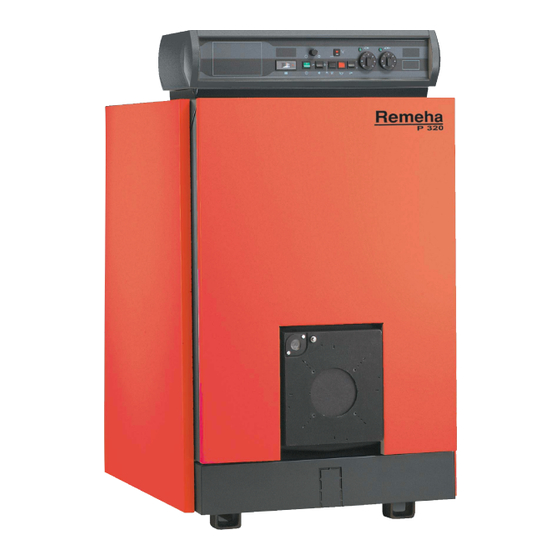
- Page 1 Remeha P 320 English Fuel oil/gas boilers 06/04/06 Technical instructions 63184...
-
Page 2: Table Of Contents
Spare parts - P 320................17 Remeha P 320... -
Page 3: Introduction
Risk of injury and damage to equipment. Attention must be paid to the warnings on Caution danger safety of persons and equipment Specific information Information must be kept in mind to maintain comfort Reference Refer to another manual or other pages in this instruction manual 06/04/06 - 300008452-001-C Remeha P 320... -
Page 4: Description
The useful power of P 320 boilers is between 70 and 330 kW. Models available Boiler with control panel, which may be fitted with an optional Rematic 2945 C3K control unit for heating only or heating and domestic hot water production. Remeha P 320 06/04/06 - 300008452-001-C... -
Page 5: Technical Characteristics
1 Technical characteristics Maximum operating pressure : 6 bar Boiler thermostat setting : 30 to 90°C Safety thermostat setting : 110 °C Boiler P 320-4 P 320-5 P 320-6 P 320-7 P 320-8 P 320-9 Useful output 70-105 105-140 140-180... -
Page 6: Main Dimensions
(d) 2 1/2 heating return (flange + counter flange) (b) 2 1/2 heating outlet (flange + counter flange) (e) Rp 1 1/2 draining outlet (supplied with plug) (c) Sludge removal hole Ø Rp 2 1/2 P 320-4 P 320-5 P 320-6 P 320-7... -
Page 7: Installing The Boiler
If the boiler location is not determined precisely, leave enough space around the boiler to facilitate monitoring and maintenance operations. Boiler P 320-4 P 320-5 P 320-6 P 320-7 P 320-8... -
Page 8: Ventilation
Do not stock such products close to the boilers. If the boiler and/or peripheral equipment are corroded by such chloride or fluoride compounds, the contractual guarantee cannot be applied. Mounting For mounting instructions, see installation instructions. Remeha P 320 06/04/06 - 300008452-001-C... -
Page 9: Hydraulic Connections
Water low safety pressure-sensitive switch Recycling pump Expansion chamber Drain cock Heating circuit filling (with disconnector depending on prevailing regulations) Water treatment if TH > 25° Water meter DHW load pump Non-return valve Domestic cold water inlet 06/04/06 - 300008452-001-C Remeha P 320... -
Page 10: Important Recommendations For Connecting The Boiler To The Heating Circuit
- The water temperature in the boiler is maintained at 50°C or more ; the first stage must be set to a minimum of 30% of the nominal stage - Operation at modulated low temperature (minimum outlet temperature: 30°C) ; the first stage must be set to a minimum of 50% of the nominal stage Remeha P 320 06/04/06 - 300008452-001-C... -
Page 11: Filling The System
Comments : never replace a boiler in an existing system without carefully rinsing the system first. Install a sludge decanting pot on the return pipe, very close to the boiler. 06/04/06 - 300008452-001-C Remeha P 320... -
Page 12: Chimney Connection
Ø 180 mm : for 4 to 6 sections Ø 200 mm : for 7 to 9 sections Fit a measuring point (Ø 10 mm hole) on the flue, in order to adjust the burner (combustion check). Remeha P 320 06/04/06 - 300008452-001-C... -
Page 13: Fuel-Oil Or Gas Connections
A : Furnace door insulation B : 4 markings on Ø 170 C : 4 markings on Ø 200 D : 4 markings on Ø 220 Electrical connections Refer to the connection instructions supplied with the control panel. 06/04/06 - 300008452-001-C Remeha P 320... -
Page 14: Maintenance
- Carefully sweep the four flue ways with the brush supplied for that purpose, - Also sweep the baffle plates and the front panel, - If possible, use a vacuum cleaner, - Replace the baffle plates, - Close the door. Remeha P 320 06/04/06 - 300008452-001-C... -
Page 15: Cleaning The Casing Material
(2 butterfly nuts) and use a vacuum cleaner to remove any soot which has accumulated - Replace the cleaning hatches. (1) Stop Baffle plates Flue ways P 320-4 P 320-5 P 320-6 P 320-7 P 320-8 P 320-9 410 mm... -
Page 16: Burner Maintenance
A : Boiler type B : Year of manufacture C : Week of manufacture D : Serial no. of the appliance Remeha P 320 06/04/06 - 300008452-001-C... -
Page 17: Spare Parts - P 320
Spare parts - P 320 To order a spare part, quote the reference number next to the part required. 06/04/06 - UK300004553-002-A Boiler body 06/04/06 - 300008452-001-C Remeha P 320... - Page 18 Insulation Base frame Remeha P 320 06/04/06 - 300008452-001-C...
- Page 19 Cladding Table - RC 1 06/04/06 - 300008452-001-C Remeha P 320...
- Page 20 Markers Code no. Description Markers Code no. Description Boiler body 9757-0027 Inspection flange 82198912 Complete rear section 9495-0050 Plug 1/4" 8219-8966 Special intermediate section 8219-0539 Guide rail for combustion chamber door 8219-8976 Complete front section 8219-0017 Upper baffle plate, 410 mm 8116-0571 Nipple 8219-0018...
- Page 21 Complete rear cover, 8 sections 8553-8517 Complete rear cover, 9 sections 8553-8518 Complete front cover 8553-8520 Screw bag Control panel K - RC 1 Refer to the Spare Parts list in the panel instructions. Remeha P 320 06/04/06 - 300008452-001-C...
- Page 22 Remeha P 320 06/04/06 - 300008452-001-C...
- Page 23 Remeha P 320 06/04/06 - 300008452-001-C...
- Page 24 © Copyright All technical and technological information contained in these technical instructions, as well as any drawings and technical descriptions supplied, remain our property and shall not be multiplied without our prior consent in writing.. Ours is a policy of continuous development. We reserve the right to alter specifications without prior notification Subject to alterations...
Need help?
Do you have a question about the P 320-4 and is the answer not in the manual?
Questions and answers