
Related Manuals for HP ProCurve 2510G Series


Summary of Contents for HP ProCurve 2510G Series
- Page 1 Installation and Getting Started Guide ProCurve Switch 2510G Series www.procurve.com...
- Page 3 ProCurve Switch 2510G Series Installation and Getting Started Guide...
- Page 4 The information contained herein is subject to change without Publication Number notice. The only warranties for HP products and services are set 5992-3093 forth in the express warranty statements accompanying such April 2008 products and services.
-
Page 5: Table Of Contents
Contents 1 Introducing the Switch Front of the Switch ..........1-3 Network Ports . - Page 6 7. (Optional) Connect a Console to the Switch ....2-16 Terminal Configuration ........2-16 Direct Console Access .
- Page 7 A Switch Specifications Physical ........... A-1 Electrical .
- Page 8 C Safety and EMC Regulatory Statements Safety Information ..........C-1 Informations concernant la sécurité...
-
Page 9: Introducing The Switch
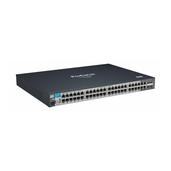
Introducing the Switch The ProCurve Switch 2510G-24 and Switch 2510G-48 are multiport Gigabit switches ideal for building high-performance small business networks. These switches are store-and-forward devices offering low latency for high-speed networking. ProCurve Switch 2510G-24 (J9279A) ProCurve Switch 2510G-48 (J9280A) The Switch 2510G-24 and Switch 2510G-48 have, respectively, 24 or 48 auto- sensing 10/100/1000Base-T RJ-45 ports, four dual-personality ports—either auto-sensing 10/100/1000Base-T RJ-45 or mini-GBIC. - Page 10 Introducing the Switch These switches are designed to be used primarily as a high-density wiring closet or desktop switch. These switches can directly connect computers, printers, and servers to provide dedicated bandwidth to those devices, and can build a switched network infrastructure by connecting the switch to hubs, other switches, or routers.
-
Page 11: Front Of The Switch
Introducing the Switch Front of the Switch Front of the Switch ProCurve Switch 2510G-24 Power, Fault Test and Fan Switch port LEDs and Locator Status LEDs LEDs LED Mode select button Dual-personality ports and indicator LEDs (10/100/1000Base-T* or 10/100/1000Base-T Console port mini-GBIC, SFP) RJ-45 ports* Reset and Clear... -
Page 12: Console Port
Introducing the Switch Front of the Switch ■ Four dual-personality ports. Use either the 10/100/1000Base-T RJ-45 connector, or install a supported ProCurve mini-GBIC (SFP) for fiber- optic connections. The RJ-45 connectors support the Auto-MDIX feature, which means you can use either straight-through or crossover twisted-pair cables to connect any network device to the switch. -
Page 13: Leds
Introducing the Switch Front of the Switch LEDs Table 1-1. Switch LEDs Switch LEDs State Meaning Power The switch is receiving power. (green) The switch is NOT receiving power. Fault The normal state; indicates there are no fault conditions on the switch. (orange) Flashing* A fault has occurred on the switch, one of the switch ports, or the fan. -
Page 14: Led Mode Select Button And Indicator Leds
Introducing the Switch Front of the Switch Switch LEDs State Meaning Test The normal operational state; the switch is not undergoing self test. (green) The switch self test and initialization are in progress after the switch has been power cycled or reset. The switch is not operational until this LED goes off. The Self Test LED also comes on briefly when you “hot swap”... -
Page 15: Reset Button
Introducing the Switch Front of the Switch Port LED (two for each port) Link and Mode LED Mode select button and indicator LEDs Figure 1-2. LED Mode select on the Switch 2510G-48 Each port has a Link LED. If it is lit, the port has a link. If the Link LED is ■... -
Page 16: Clear Button
Introducing the Switch Back of the Switch Clear Button This button is used for these purposes: Deleting Passwords - When pressed by itself for at least one second, the ■ button deletes any switch console access passwords that you may have configured. -
Page 17: Switch Features
Introducing the Switch Switch Features Switch Features The features of the Switch 2510G Series devices include: ■ 24 or 48 auto-sensing 10/100/1000Base-T RJ-45 ports. ■ four dual-personality ports—either the auto sensing 10/100/1000Base-T RJ-45 or the mini-GBIC can be used for each port. ■... - Page 18 Introducing the Switch Switch Features ■ Support for other features to enhance network performance—for a description, see the Management and Configuration Guide, which is on the ProCurve Web site at www.procurve.com. To display the list of downloadable manuals, click on the following links: Technical support Product manuals (all) ProCurve Switch 2510G Series.
-
Page 19: Installing The Switch
Installing the Switch The ProCurve Switch 2510G Series devices are easy to install. They come with an accessory kit that includes the brackets for mounting the switch in a standard 19-inch telco rack, in an equipment cabinet, and with rubber feet that can be attached so the switch can be securely located on a horizontal surface. - Page 20 Installing the Switch Included Parts ■ Power cord, one of the following: Australia/New Zealand 8120-6803 China 8120-8377 Continental Europe 8120-6802 Denmark 8120-6806 Japan 8120-6804 Switzerland 8120-6807 United Kingdom/Hong Kong/Singapore 8120-8709 United States/Canada/Mexico 8120-6805 South Africa 8120-8929 Israel 8121-1009 Thailand 8121-0673 Taiwan 8121-0964 J a p a n P o w e r...
-
Page 21: Installation Precautions
Installing the Switch Included Parts Installation Precautions: Follow these precautions when installing the Switch 2510G Series devices. W A R N I N G ■ The rack or cabinet should be adequately secured to prevent it from becoming unstable and/or falling over. Devices installed in a rack or cabinet should be mounted as low as possible, with the heaviest devices at the bottom and progressively lighter devices installed above. -
Page 22: Installation Procedures
Installing the Switch Installation Procedures Figure 2-1. Air flow direction of the 2510G switch Installation Procedures Summary Follow these steps to install the switch. The rest of this chapter provides details on these steps. Prepare the installation site (page 2-5). Ensure the physical environ- ment is properly prepared, including having the correct network cabling ready to connect to the switch and having an appropriate location for the switch. -
Page 23: Prepare The Installation Site
Installing the Switch Installation Procedures Connect the network cables (page 2-15). Using the appropriate network cables, connect the network devices to the switch ports. 2-16). You may wish Connect a console to the switch (optional—page to modify the switch’s configuration, for example, to configure an IP address so it can be managed using a web browser, from an SNMP network management station, or through a Telnet session. - Page 24 Installing the Switch Installation Procedures Port Type Cable Type Length Limits Fiber Optic Cables • 62.5 μm cable: Gigabit-SX Multimode fiber-optic cables designed for Gigabit Ethernet: 62.5/125 μm or 50/125 μm (on Gigabit-SX-LC – 160 MHz*km = 220 meters mini-GBIC) (core/cladding) diameter, low metal content, –...
-
Page 25: Installing Or Removing Mini-Gbics (Sfps)
Installing the Switch Installation Procedures 2. Installing or Removing mini-GBICs (SFPs) You can install or remove a mini-GBIC or SFP from a mini-GBIC slot without having to power off the switch. Use only ProCurve mini-GBICs and transceivers. N o t e s ■... -
Page 26: Removing The Mini-Gbics
Installing the Switch Installation Procedures Figure 2-2. Example of installing a mini-GBIC (SFP) Removing the mini-GBICs N o t e The network cable should be disconnected from the mini-GBIC before removing it from the switch. Depending on when you purchased your ProCurve mini-GBIC, it may have either of three different release mechanisms: a plastic tab on the bottom of the mini-GBIC, a plastic collar around the mini-GBIC, or a wire bail. -
Page 27: Verify The Switch Passes Self Test
Installing the Switch Installation Procedures 3. Verify the Switch Passes Self Test Before mounting the switch in its network location, you should first verify it is working properly by plugging it into a power source and verifying it passes self test. Connect the power cord supplied with the switch to the power connector on the back of the switch, and then into a properly grounded electrical outlet. -
Page 28: Led Behavior
Installing the Switch Installation Procedures Check the LEDs on the switch as described below. Switch port LEDs Power, Fault Test LED and locator LEDs Figure 2-4. Checking the LEDs on the 2510G-24 (J9279A) Switch port LEDs Power and Test LED Fault LEDs Figure 2-5. -
Page 29: Mount The Switch
Installing the Switch Installation Procedures When the self test completes successfully: • The Power and Fan Status LEDs remain on. • The Fault and Test LEDs go off. • The port LEDs on the front of the switch go into their normal opera- tional mode: –... -
Page 30: Rack Mounting The Switch 2510G-48
Installing the Switch Installation Procedures Rack Mounting the Switch 2510G-48 Use a #1 Phillips (cross-head) screwdriver and attach the mounting brackets to the switch with the included 8-mm M4 screws. 8 mm M4 screws Figure 2-6. Example of attaching mounting brackets N o t e The mounting brackets have multiple mounting holes and can be rotated allowing for a wide variety of mounting options. -
Page 31: Wall Mounting
Installing the Switch Installation Procedures Wall Mounting C a u t i o n The J9279A 24-port switch can be wall mounted with the RJ-45 port side facing down only in the horizontal orientation. A vertical wall mount orientation is not supported. -
Page 32: Horizontal Surface Mounting
Installing the Switch Installation Procedures Horizontal Surface Mounting Place the switch on a table or other horizontal surface. The switch comes with rubber feet in the accessory kit that can be used to help keep the switch from sliding on the surface. Attach the rubber feet to the four corners on the bottom of the switch within the embossed angled lines. -
Page 33: Connect The Network Cables
Installing the Switch Installation Procedures 6. Connect the Network Cables Connect the network cables, described under “Cabling Infrastructure” (page 2-5), from the network devices or your patch panels to the fixed RJ-45 ports on the switch or to any mini-GBICs you have installed in the switch. Using the RJ-45 Connectors To connect: Push the RJ-45 plug into the RJ-45 jack... -
Page 34: Optional) Connect A Console To The Switch
Installing the Switch Installation Procedures 7. (Optional) Connect a Console to the Switch The switch has a full-featured, easy to use console interface for performing switch management tasks including the following: Monitor switch and port status and observe network activity statistics ■... -
Page 35: Direct Console Access
Installing the Switch Installation Procedures Direct Console Access To connect a console to the switch, follow these steps: Connect the PC or terminal to the switch’s Console port Console Port using the console cable included with the Switch. (If your PC or terminal has a 25-pin Console cable supplied serial connector, first... -
Page 36: Console Cable Pinouts
Installing the Switch Installation Procedures Console Cable Pinouts The console cable has an RJ-45 male connector on one end and a DB-9 female connector on the other end. Table 2-12 describes the mapping of the RJ-45 to DB-9 pins. 1 2 3 4 5 6 7 8 1 2 3 4 5 6 7 8 Figure 2-11. -
Page 37: Sample Network Topologies
Installing the Switch Sample Network Topologies Sample Network Topologies This section shows a few sample network topologies in which the Switch is implemented. For more topology information, see the ProCurve networking products Web site, www.procurve.com As a Desktop Switch Server, with Gigabit Ethernet NIC ProCurve Switch 2510G-24 PCs, local servers,... -
Page 38: As A Segment Switch
Server, with Gigabit Ethernet NIC ProCurve Switch 2510G-24 To Backbone Fast Ethernet Switch Fast Ethernet Switch hp pr ocur ve hp pr ocur ve s w i tch 2650 s w i tch 2650 J 4899A J 4899A P ower... - Page 39 Installing the Switch Sample Network Topologies Category 3 or 4 cable can also be used if the connection is 10 Mbps only. In all cases, the device ports must be configured to auto negotiate the link charac- teristics for this feature to work. The switch, in turn, can be connected to a network backbone through fiber- optic cabling connected to a Gigabit-SX, -LX, or -LH mini-GBIC installed in the switch.
-
Page 40: Connecting To A Backbone Switch
ProCurve Switch 5406zl ProCurve Switch 2510G-48 Server, with Gigabit Ethernet NIC Fast Ethernet Switch Fast Ethernet Switch hp pr ocur v e hp pr ocur ve s w it ch 2650 s w i tch 2650 J4899A J 4899A P ower... -
Page 41: Stacking The Switch
Installing the Switch Sample Network Topologies The simpler desktop and segment networks shown in the previous two examples can easily be combined and expanded. For example, you could use a ProCurve Switch 5406zl to interconnect each of your smaller switched workgroups to form a larger switched network. - Page 42 Installing the Switch Sample Network Topologies To Gigabit-Ethernet Backbone Gigabit link (use fiber if over 100 meters ProCurve Switch 2510G-48 ProCurve Switch 2510G-48 ProCurve Switch 2510G-24 ProCurve Switch 2510G-24 L E GE ND: Gigabit E thernet cable Figure 2-16. Example of stacking switches 2-24...
-
Page 43: Configuring The Switch
Configuring the Switch This chapter is a guide for using the console Switch Setup screen to quickly assign an IP (Internet Protocol) address and subnet mask to the switch, set a Manager password, and, optionally, configure other basic features. For more information on using the switch console and the other switch management interfaces (such as the web browser interface), please see the Management and Configuration Guide, which is available on the ProCurve Web site www.procurve.com. -
Page 44: Using The Console Setup Screen
Configuring the Switch N o t e By default, the switch is configured to acquire an IP address configuration from a DHCP or Bootp server. To use DHCP/Bootp instead of the manual method described in this chapter, see “DHCP/Bootp Operation” in the Management and Configuration Guide, which is available on the ProCurve Web site www.procurve.com. - Page 45 Configuring the Switch to the IP Config (DHCP/Bootp) field and use the Space bar to select the [Tab] Manual option. to the IP Address field and enter the IP address that is compatible with [Tab] your network. to the Subnet Mask field and enter the subnet mask used for your [Tab] network.
-
Page 46: Where To Go From Here
Configuring the Switch Where to Go From Here The above procedure configures your switch with a Manager password, IP address, and subnet mask. As a result, with the proper network connections, you can now manage the switch from a PC equipped with Telnet or a web browser interface. -
Page 47: Using The Ip Address For Remote Switch Management
Configuring the Switch Using the IP Address for Remote Switch Management Using the IP Address for Remote Switch Management With the Switch 2510G Series devices, you can use the switch’s IP address to manage the switch from any PC that is on the same subnet as the switch. You can use either a Telnet session or a standard web browser to manage the switch. - Page 48 Configuring the Switch Using the IP Address for Remote Switch Management For more information on using the web browser interface, please see the Management and Configuration Guide, which is available on the ProCurve Web site www.procurve.com. An extensive help system is also available for the web browser interface. To access the help system though the subnet on which the switch is installed you must have access to the internet.
-
Page 49: Troubleshooting
4-11) downloading new software to the Switch 2510G Series devices (page 4-12) ■ ■ HP Customer Support Services (page 4-12) Basic Troubleshooting Tips Most problems are caused by the following situations. Check for these items first when starting your troubleshooting: ■... - Page 50 Troubleshooting Basic Troubleshooting Tips Because the Switch 2510G Series devices behave in this way (in compliance with the IEEE 802.3 standard), if a device connected to the switch has a fixed configuration at full duplex, the device will not connect correctly to the switch.
- Page 51 Troubleshooting Basic Troubleshooting Tips ■ Check the port configuration. A port on your Switch may not be operating as you expect because it has been put into a “blocking” state by Spanning Tree, GVRP (automatic VLANs), or LACP (automatic trunking). (Note that the normal operation of the Spanning Tree, GVRP, and LACP features may put the port in a blocking state.) Or, the port just may have been configured as disabled through software.
-
Page 52: Diagnosing With The Leds
Troubleshooting Diagnosing with the LEDs Diagnosing with the LEDs Table 3-1 shows LED patterns on the switch and the switch modules that indicate problem conditions. Check in the table for the LED pattern you see on your switch. Refer to the corresponding diagnostic tip on the next few pages. Table 4-1. -
Page 53: Diagnostic Tips
Try power cycling the switch. If the fault indication reoccurs, the switch port may have for which the LED failed. Call your HP authorized LAN dealer, or use the electronic support services from HP is flashing has to get assistance. See the Customer Support/Warranty booklet for more information. - Page 54 Troubleshooting Diagnosing with the LEDs Problem Solution ➏ The network Try the following procedures: connection is not • For the indicated port, verify both ends of the cabling, at the switch and the connected working device, are connected properly. properly. •...
- Page 55 Troubleshooting Diagnosing with the LEDs Problem Solution ➐ The port may be Use the switch console to see if the port is part of a dynamic trunk (through the LACP improperly feature) or to see if Spanning Tree is enabled on the switch, and to see if the port may have configured, or been put into a “blocking”...
-
Page 56: Proactive Networking
Troubleshooting Proactive Networking Proactive Networking The ProCurve Switch 2510G Series devices have built-in management capabilities that proactively help you manage your network including: ■ finding and helping you fix the most common network error conditions (for example, faulty network cabling, and non-standard network topologies) informing you of the problem with clear, easy-to-understand log messages ■... -
Page 57: Hardware Diagnostic Tests
Troubleshooting Hardware Diagnostic Tests Hardware Diagnostic Tests Testing the Switch by Resetting It If you believe the switch is not operating correctly, you can reset the switch to test its circuitry and operating code. To reset a switch, either: ■ Unplug and plug in the power cord (power cycling) Press the Reset button on the front of the switch ■... -
Page 58: Testing Twisted-Pair Cabling
Troubleshooting Hardware Diagnostic Tests Testing Twisted-Pair Cabling Network cables that fail to provide a link or provide an unreliable link between the switch and the connected network device may not be compatible with the IEEE 802.3 Type 10Base-T, 100Base-TX, or 1000Base-T standards. The twisted-pair cables attached to the Switch must be compatible with the appropriate standards. -
Page 59: Restoring The Factory Default Configuration
Troubleshooting Restoring the Factory Default Configuration Restoring the Factory Default Configuration As part of your troubleshooting process on the Switch, it may become necessary to return the switch configuration to the factory default settings. This process momentarily interrupts the switch operation, clears any passwords, clears the console event log, resets the network counters to zero, performs a complete self test, and reboots the switch into its factory default configuration including deleting the IP address, if one is configured. -
Page 60: Downloading New Switch Software
Troubleshooting Downloading New Switch Software Downloading New Switch Software When product enhancements occur for the Switch 2510G Series devices, new software can be downloaded to the switch through several methods. For more information, see the Management and Configuration Guide, which is available on the ProCurve Web site, www.procurve.com ProCurve Customer Support Services... -
Page 61: A Switch Specifications
Switch Specifications Physical 2510G-24 (J9279A) 2510G-48 (J9280A) Width: 44.3 cm (17.42 in) 44.3 cm (17.42 in) Depth: 32.3 cm (12.7 in) 33.3 cm (12.7 in) Height: 4.4 cm (1.73 in) 4.4 cm (1.73 in) Weight: 3.3 kg (7.2 lbs) 3.9 kg (8.6 lbs) Electrical The switch automatically adjusts to any voltage between 100-240 volts and either 50 or 60 Hz. -
Page 62: Connectors
Switch Specifications Acoustic 2510G-24 Geraeuschemission LpA=40.3 dB am fiktiven Arbeitsplatz nach DIN 45635 T.19 Noise Emission LpA=40.3 dB at virtual workspace according to DIN 45635 T.19 2510G-48 Geraeuschemission LpA=40.5 dB am fiktiven Arbeitsplatz nach DIN 45635 T.19 Noise Emission LpA=40.5 dB at virtual workspace according to DIN 45635 T.19 Connectors The 10/100/1000 Mbps RJ-45 twisted-pair ports are compatible with the ■... -
Page 63: B Switch Ports And Network Cables
N o t e Incorrectly wired cabling is the most common cause of problems for LAN communications. HP recommends that you work with a qualified LAN cable installer for assistance with your cabling requirements. Switch Ports The fixed RJ-45 10/100/1000Base-T ports on the switch accept 100-ohm unshielded and shielded twisted-pair cable with RJ-45 connectors as described on the next page. -
Page 64: Fiber-Optic Cables
Switch Ports and Network Cables Switch Ports Because of the increased speed provided by 1000Base-T (Gigabit-T), network cable quality is more important than for either 10Base-T or 100Base-TX. Cabling plants being used to carry 1000Base-T networking must comply with the IEEE 802.3ab standards. In particular, the cabling must pass tests for Attenuation, Near-End Crosstalk (NEXT), and Far-End Crosstalk (FEXT). -
Page 65: Mode Conditioning Patch Cord For Gigabit-Lx
Switch Ports and Network Cables Mode Conditioning Patch Cord for Gigabit-LX Mode Conditioning Patch Cord for Gigabit-LX The following information applies to installations in which multimode fiber- optic cables are connected to a Gigabit-LX port. Unlike Gigabit-SX, which connects to only multimode fiber-optic cabling, Gigabit-LX can use either single-mode or multimode cable. -
Page 66: Installing The Patch Cord
Switch Ports and Network Cables Mode Conditioning Patch Cord for Gigabit-LX Installing the Patch Cord As shown in the illustration below, connect the patch cord to the Gigabit-LX mini-GBIC with the section of single-mode fiber plugged in to the Tx (transmit) port. -
Page 67: Twisted-Pair Cable/Connector Pin-Outs
Switch Ports and Network Cables Twisted-Pair Cable/Connector Pin-Outs Twisted-Pair Cable/Connector Pin-Outs The Auto-MDIX Feature: In the default configuration, “Auto”, the fixed 10/ 100Base-TX ports on the Switch 2510G Series all automatically detect the type of port on the connected device and operate as either an MDI or MDI-X port, whichever is appropriate. - Page 68 Switch Ports and Network Cables Twisted-Pair Cable/Connector Pin-Outs ■ For 100 Mbps connections to the ports, use 100-ohm Category 5 UTP or STP cable only, as supported by the IEEE 802.3u Type 100Base-TX standard. For 1000 Mbps connections, 100-ohm Category 5e or better cabling is ■...
-
Page 69: Straight-Through Twisted-Pair Cable For 10 Mbps Or 100 Mbps Network Connections
Switch Ports and Network Cables Twisted-Pair Cable/Connector Pin-Outs Straight-through Twisted-Pair Cable for 10 Mbps or 100 Mbps Network Connections Because of the Auto-MDIX operation of the 10/100 ports on the switch, for all network connections, to PCs, servers or other end nodes, or to hubs or other switches, you can use straight-through cables. -
Page 70: Crossover Twisted-Pair Cable For 10 Mbps Or 100 Mbps Network Connection
Switch Ports and Network Cables Twisted-Pair Cable/Connector Pin-Outs Crossover Twisted-Pair Cable for 10 Mbps or 100 Mbps Network Connection The Auto-MDIX operation of the 10/100 ports on the switch also allows you to use crossover cables for all network connections, to PCs, servers or other end nodes, or to hubs or other switches. -
Page 71: Straight-Through Twisted-Pair Cable For 1000 Mbps Network Connections
Switch Ports and Network Cables Twisted-Pair Cable/Connector Pin-Outs Straight-Through Twisted-Pair Cable for 1000 Mbps Network Connections 1000Base-T connections require that all four pairs of wires be connected. Cable Diagram N o t e Pins 1 and 2 on connector “A” must be wired as a twisted pair to pins 1 and 2 on connector “B”. -
Page 73: C Safety And Emc Regulatory Statements
Safety and EMC Regulatory Statements Safety Information Documentation reference symbol. If the product is marked with this symbol, refer to the product documentation to get more information about the product. WARNING A WARNING in the manual denotes a hazard that can cause injury or death. -
Page 74: Informations Concernant La Sécurité
Safety and EMC Regulatory Statements Informations concernant la sécurité Informations concernant la sécurité Symbole de référence à la documentation. Si le produit est marqué de ce symbole, reportez-vous à la documentation du produit afin d'obtenir des informations plus détaillées. WARNING Dans la documentation, un WARNING indique un danger susceptible d'entraîner des dommages corporels ou la mort. -
Page 75: Hinweise Zur Sicherheit
Safety and EMC Regulatory Statements Hinweise zur Sicherheit Hinweise zur Sicherheit Symbol für Dokumentationsverweis. Wenn das Produkt mit diesem Symbol markiert ist, schlagen Sie bitte in der Produktdokumentation nach, um mehr Informationen über das Produkt zu erhalten. WARNING Eine WARNING in der Dokumentation symbolisiert eine Gefahr, die Verletzungen oder sogar Todesfälle verursachen kann. -
Page 76: Considerazioni Sulla Sicurezza
Safety and EMC Regulatory Statements Considerazioni sulla sicurezza Considerazioni sulla sicurezza Simbolo di riferimento alla documentazione. Se il prodotto è contras- segnato da questo simbolo, fare riferimento alla documentazione sul prodotto per ulteriori informazioni su di esso. WARNING La dicitura WARNINGdenota un pericolo che può causare lesioni o morte. -
Page 77: Consideraciones Sobre Seguridad
Safety and EMC Regulatory Statements Consideraciones sobre seguridad Consideraciones sobre seguridad Símbolo de referencia a la documentación. Si el producto va marcado con este símbolo, consultar la documentación del producto a fin de obtener mayor información sobre el producto. WARNING Una WARNING en la documentación señala un riesgo que podría resultar en lesiones o la muerte. -
Page 78: Safety Information (Japan
Safety and EMC Regulatory Statements Safety Information (Japan) Safety Information (Japan) J a p a n P o w e r C o r d W a r n i n g... -
Page 79: Safety Information (China
Safety and EMC Regulatory Statements Safety Information (China) Safety Information (China) -
Page 80: Emc Regulatory Statements
Safety and EMC Regulatory Statements EMC Regulatory Statements EMC Regulatory Statements U.S.A. FCC Class A This equipment has been tested and found to comply with the limits for a Class A digital device, pursuant to Part 15 of the FCC Rules. These limits are designed to provide reasonable protection against interference when the equipment is operated in a commercial environment. -
Page 81: Korea
Safety and EMC Regulatory Statements EMC Regulatory Statements Korea Taiwan... -
Page 82: European Community
Safety and EMC Regulatory Statements EMC Regulatory Statements European Community DECLARATION OF CONFORMITY according to ISO/IEC 17050-1 and EN17050-1 ______________________________________________________________________ Supplier's Name: Hewlett-Packard Company DOC#: RSVLC-0509-03042008 Supplier's Address: 8000 Foothills Blvd. Roseville, CA 95747-5502 U.S.A. declares, that the product Product Name : ProCurve Switch 2510-48, ProCurve Switch 2810-24G, ProCurve Switch 2810-48G, ProCurve Switch 2510G-24, ProCurve Switch 2510G-48... - Page 83 Regulatory Information (China) (Hg) (Cd) (Pb) (Cr(VI)) (PBB) (PCA) SJ/T11363-2006 SJ/T11363-2006 ProCurve Networking by HP This information is required by the People’s Republic of China as per their legislation titled “Management Methods for Controlling Pollution by Electronic Information Products”. C-11...
-
Page 85: D Recycle Statements
Recycle Statements Waste Electrical and Electronic Equipment (WEEE) Statements Disposal of Waste Equipment by Users in Private Household in the European Union This symbol on the product or on its packaging indicates that this product must not be disposed of with your other household waste. - Page 86 Recycle Statements Waste Electrical and Electronic Equipment (WEEE) Statements Laitteiden hävittäminen kotitalouksissa Euroopan unionin alueella Jos tuotteessa tai sen pakkauksessa on tämä merkki, tuotetta ei saa hävittää kotitalousjätteiden mukana. Tällöin hävitettävä laite on toimitettava sähkölaitteiden ja elektronisten laitteiden kierrätyspisteeseen. Hävitettävien laitteiden erillinen käsittely ja kierrätys auttavat säästämään luonnonvaroja ja varmistamaan, että...
- Page 87 Recycle Statements Waste Electrical and Electronic Equipment (WEEE) Statements Smaltimento delle apparecchiature da parte di privati nel territorio dell'Unione Europea Questo simbolo presente sul prodotto o sulla sua confezione indica che il prodotto non può essere smaltito insieme ai rifiuti domestici. È responsabilità dell'utente smaltire le apparecchiature consegnan- dole presso un punto di raccolta designato al riciclo e allo smaltimento di apparecchiature elettriche ed elettroniche.
- Page 88 Para obter mais informações sobre locais que reciclam esse tipo de material, entre em contato com o escritório da HP em sua cidade, com o serviço de coleta de lixo ou com a loja em que o produto foi adquirido.
- Page 89 LED … 1-7 connections … 2-6 auto MDI/MDI-X operation … B-7, B-9 connecting cables to switch ports … 2-15 HP Auto-MDIX feature … B-5 effects of non-standard cables … 4-2 fiber-optic, specifications … B-2 infrastructure requirements … 2-5 length limitations … 2-5 back of switch required types …...
- Page 90 … 2-17 switch-to-switch or hub connection … B-8 Switch Setup screen … 3-2 cables, twisted-pair Telnet access … 3-5 HP Auto-MDIX feature … B-5 terminal configuration … 2-16 wiring rules … B-5 console port cables, twisted-pair connector pin-outs … B-5 location on switch …...
- Page 91 EMC regulatory statements … C-8 environmental specifications, switch … A-1 horizontal surface mounting switch on … 2-14 HP Auto-MDIX feature description … B-5 factory default configuration, restoring … 4-11 factory default configuration,restoring … 1-8 Fan Status LED … 1-6 Fault LED … 1-5 in-band …...
- Page 92 … 2-14 10/100Base-TX, location on switch … 1-3 connecting to … 2-15 console … 2-16 network cables HP Auto-MDIX feature … B-5 1000Base-LH connections … 2-6 network connections … 2-15 1000Base-LX connections … 2-6 power connector … 1-8 1000Base-SX connections …...
- Page 93 Proactive Network tools summary diagnostics with … 4-8 of cables used with the switch … 2-5 of switch installation … 2-4 switch connecting to a power source … 2-14 rack description … 1-1 mounting precautions … 2-3 downloading new software … 4-12 mounting the switch in …...
- Page 94 … B-7, B-9 switch-to-computer connection … B-7, B-9 switch-to-switch or hub connection … B-8 testing … 4-10 twisted-pair ports HP Auto-MDIX feature … B-5 VT-100 terminal serial cable connection for … 2-17 wiring rules for twisted-pair cables … B-5 6 – Index...
- Page 96 © Copyright 2008 Hewlett-Packard Development Company, L.P. Printed in Taiwan April 2008 Manual Part Number 5992-3093 *5992-3093*...
Need help?
Do you have a question about the ProCurve 2510G Series and is the answer not in the manual?
Questions and answers