Table of Contents
Advertisement
Advertisement
Table of Contents

Related Manuals for HP J4897A


Summary of Contents for HP J4897A
- Page 1 installation guide hp procurve series 2700 switches www.hp.com/go/hpprocurve...
- Page 3 HP Procurve Series 2700 Switches Installation Guide...
- Page 4 5990-3055 performance, or use of this material. October 2002 Hewlett-Packard assumes no responsibility for the use or reliability of its software on equipment that is not furnished Applicable Products by Hewlett-Packard. HP Procurve Switch 2708 (HP J4898A)
-
Page 5: Table Of Contents
Contents 1 Introducing the HP Procurve Series 2700 Switches Front of the Switch ..........1-2 Network Ports . - Page 6 3 Troubleshooting Basic Troubleshooting Tips ........3-1 Diagnosing with the LEDs .
- Page 7 C Safety and EMC Regulatory Statements Safety Information ......... . . C-1 EMC Regulatory Statements .
-
Page 9: Introducing The Hp Procurve Series 2700 Switches
HP Procurve Switch 2708 (HP J4898A) Mbps Mbps Mbps HP Procurve Switch 2724 (HP J4897A) Mbps Mbps Mbps Throughout this manual, these switches will be abbreviated as the Switch 2708 and the Switch 2724 respectively. -
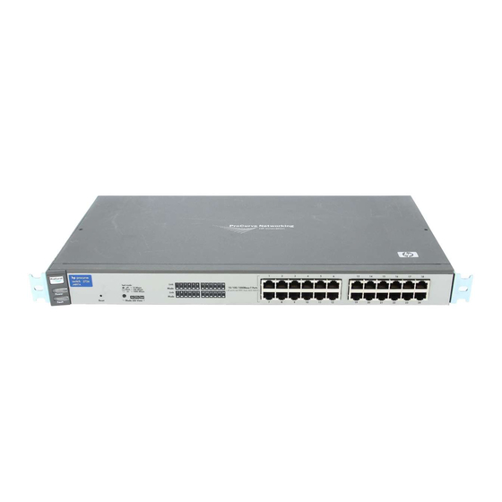
Page 10: Front Of The Switch
Introducing the HP Procurve Series 2700 Switches Front of the Switch Front of the Switch Power Fault 10/100/1000Base-T RJ-45 ports Mbps Mbps Mbps Link and Mode LEDs Mode LED View button Reset button for each port and indicator LEDs Mbps Mbps Mbps 10/100/1000Base-T RJ-45 ports... -
Page 11: Leds
Introducing the HP Procurve Series 2700 Switches Front of the Switch LEDs Table 1-1. Switch LEDs Switch LEDs State Meaning Power The switch is receiving power. (green) The switch is NOT receiving power. Fault The normal state; indicates that there are no fault conditions on the switch. (orange) On briefly after the switch is powered on or reset, at the beginning of switch self test. -
Page 12: Mode Led View Button And Indicator Leds
Introducing the HP Procurve Series 2700 Switches Front of the Switch Mode LED View Button and Indicator LEDs To optimize the amount of information that can be displayed for each of the switch ports, the Series 2700 Switches use a Mode LED for each port. The operation of this LED is controlled by the Mode LED View button, and the current setting is indicated by the Mode indicator LEDs near the button. -
Page 13: Back Of The Switch
Introducing the HP Procurve Series 2700 Switches Back of the Switch Back of the Switch cooling vents - make sure these are not obstructed for proper switch operation AC power connector Power Connector The Series 2700 Switches do not have a power switch; they are powered on when connected to an active AC power source. -
Page 14: Features
Introducing the HP Procurve Series 2700 Switches Features Features The features of the Series 2700 Switches include: 8 or 24 auto-sensing 10/100/1000Base-T RJ-45 ports. ■ ■ plug-and-play networking — all ports are enabled — just connect the network cables to active network devices and your switched network is operational. -
Page 15: Switch Operation Overview
Introducing the HP Procurve Series 2700 Switches Switch Operation Overview Switch Operation Overview Address Table Operation Address Learning. As devices are connected to the switch ports, either directly or through hubs or other switches that are connected to the switch, the MAC addresses of those devices are learned automatically and stored in the Series 2700 Switch’s address table. -
Page 17: Installing The Series 2700 Switches
Installing the Series 2700 Switches The HP Series 2700 Switches are easy to install. They come with an accessory kit that includes the brackets for mounting the switch in a standard 19-inch telco rack or an equipment cabinet, or on a wall, and with rubber feet that can be attached so the switch can be securely located on a horizontal surface. -
Page 18: Installation Procedures
Installing the Series 2700 Switches Installation Procedures Installation Procedures Summary Follow these easy steps to install your switch. The rest of this chapter provides details on these steps. Prepare the installation site. Make sure that the physical environment into which you will be installing the switch is properly prepared including having the correct network cabling ready to connect to the switch, and having a good location for the switch. -
Page 19: Installation Precautions
Installing the Series 2700 Switches Installation Procedures Installation Precautions: Follow these precautions when installing your HP Series 2700 Switches. W a r n i n g s The rack or cabinet should be adequately secured to prevent it from ■ becoming unstable and/or falling over. -
Page 20: Prepare The Installation Site
Installing the Series 2700 Switches Installation Procedures 1. Prepare the Installation Site ■ Cabling Infrastructure - Ensure that the cabling infrastructure meets the necessary network specifications. See the following table for cable types and lengths, and see appendix B, “Switch Ports and Network Cables”... -
Page 21: Verify The Switch Operates Correctly
Installing the Series 2700 Switches Installation Procedures 2. Verify the Switch Operates Correctly Before mounting the switch in its network location, you should first check that it is working properly by plugging it into a power source and verifying that it passes its self test. Connect the power cord supplied with the switch to the power connector on the back of the switch, and then into a nearby properly grounded electrical outlet. -
Page 22: Led Behavior
Installing the Series 2700 Switches Installation Procedures switch port LEDs Mbps Mbps Mbps Power and Fault LEDs When the switch is powered on, it performs its diagnostic self test. The self test takes approximately 6 seconds to complete. LED Behavior: During the self test: •... -
Page 23: Mount The Switch
Installing the Series 2700 Switches Installation Procedures 3. Mount the Switch After you have verified that the switch passes its self test, you are ready to mount the switch in a stable location. The Series 2700 Switches can be mounted in these ways: ■... - Page 24 Installing the Series 2700 Switches Installation Procedures Use a #1 Phillips (cross-head) screwdriver and attach the mounting brackets to the switch with the included 8-mm M4 screws. 8 mm M4 screws N o t e Note that the mounting brackets have multiple mounting holes and can be rotated allowing for a wide variety of mounting options.
- Page 25 Installing the Series 2700 Switches Installation Procedures Partially install a screw (5/8-inch number 12-24) into the top hole of a pair of holes that are 0.5 inches apart in each rack/cabinet upright as shown in the illustration below. Ensure that the screws are at the same level in each upright.
-
Page 26: Wall Mounting
Installing the Series 2700 Switches Installation Procedures Install the other number 12-24 screw into the upper hole in each bracket. Tighten these screws. install additional screw Wall Mounting You can mount the switch on a wall as shown in the illustrations on the next page. - Page 27 Installing the Series 2700 Switches Installation Procedures For “Bookshelf” Wall Mounting For “Flat” Wall Mounting 5/8-inch M4 screws wood screw M4 screws 5/8-inch wood screws second 5/8-inch wood screw (hidden) Note that the brackets are attached on opposite corners. This improves the stability of the switch on the wall.
-
Page 28: Horizontal Surface Mounting
Installing the Series 2700 Switches Installation Procedures Horizontal Surface Mounting Place the switch on a table or other horizontal surface. The switch comes with rubber feet in the accessory kit that can be used to help keep the switch from sliding on the surface. -
Page 29: Using The Rj-45 Connectors
Installing the Series 2700 Switches Installation Procedures Using the RJ-45 Connectors To connect: Push the RJ-45 plug into the RJ-45 jack until the tab on the plug clicks into place. When power is on for the switch and for the connected device, the Link LED for the port should light to confirm a powered-on device (for example, an end node) is at the other... -
Page 30: Example Network Topology
Installing the Series 2700 Switches Example Network Topology Example Network Topology This section shows you an example network topology in which the Series 2700 Switches are implemented. For more topology information, see the HP network products World Wide Web site, http://www.hp.com/go/hpprocurve. As a Desktop Switch category 5E twisted-pair “straight- Switch 2708... -
Page 31: Troubleshooting
Troubleshooting This chapter describes how to troubleshoot your Series 2700 Switch including the following: ■ basic troubleshooting tips (page 3-1) ■ diagnosing with the LEDs (page 3-3) hardware diagnostic tests (page 3-4) ■ ■ HP Customer Support Services (page 3-5) Basic Troubleshooting Tips Most problems are caused by the following situations. - Page 32 Troubleshooting Basic Troubleshooting Tips ■ Faulty or loose cables. Look for loose or obviously faulty connections. If they appear to be OK, make sure the connections are secure. If that does not correct the problem, try a different cable. Non-standard cables. Non-standard and miswired cables may cause ■...
-
Page 33: Diagnosing With The Leds
Troubleshooting Diagnosing with the LEDs Diagnosing with the LEDs Table 3-1 shows LED patterns on the switch that indicate problem conditions. Check in the table for the LED pattern that you see on your switch. Refer to the corresponding diagnostic tip on the next few pages. Table 3-1. -
Page 34: Hardware Diagnostic Tests
Troubleshooting Hardware Diagnostic Tests Number Problem Solution ➌ The network Try the following procedures: connection is not • For the indicated port, verify that both ends of the cabling, at the switch and the working properly. connected device, are connected properly. •... -
Page 35: Testing Twisted-Pair Cabling
Ping test. HP Customer Support Services If you are still having trouble with your switch, Hewlett-Packard offers support 24 hours a day, seven days a week through the use of a number of automated electronic services. See the Customer Support/Warranty booklet that came with your switch for information on how to use these services to get technical support. -
Page 37: Physical
Specifications Physical Switch 2708 Switch 2724 Width: 44.3 cm (17.4 in) 44.3 cm (17.4 in) Depth: 23.7 cm (9.3 in) 23.7 cm (9.3 in) Height: 4.4 cm (1.7 in) 4.4 cm (1.7 in) Weight : 3.1 kg (6.8 lbs) 3.5 kg (7.6 lbs) Electrical Each Series 2700 Switch automatically adjusts to any voltage between 100-240 volts and either 50 or 60 Hz. -
Page 38: Connectors
Specifications Connectors The 10/100/1000 Mbps RJ-45 twisted-pair ports are compatible with the following standards: IEEE 802.3ab 1000Base-T ■ ■ IEEE 802.3u 100Base-TX IEEE 802.3 10Base-T ■ Safety The Series 2700 Switches comply with these safety standards: EN60950 / IEC 950 ■... -
Page 39: B Switch Ports And Network Cables
Switch Ports and Network Cables This appendix includes switch connector information and network cable information for cables that should be used with the Series 2700 Switches, including minimum pin-out information and specifications for twisted-pair cables. N o t e Incorrectly wired cabling is the most common cause of problems for LAN communications. - Page 40 Switch Ports and Network Cables Note on 1000Base-T Cable Requirements. The Category 5 networking cables that work for 100Base-TX connections should also work for 1000Base-T, as long as all four-pairs are connected. But, for the most robust connections you should use cabling that complies with the Category 5E specifications, as described in Addendum 5 to the TIA-568-A standard (ANSI/ TIA/EIA-568-A-5).
-
Page 41: Twisted-Pair Cable/Connector Pin-Outs
Switch Ports and Network Cables Twisted-Pair Cable/Connector Pin-Outs Twisted-Pair Cable/Connector Pin-Outs The IEEE 802.3ab “Auto MDI/MDI-X” Feature: The 10/100/1000Base-T ports on the Series 2700 Switches all have the “Auto MDI/MDI-X” feature that is part of the IEEE 802.3ab standard. They automatically detect the type of port on any device connected to the Series 2700 Switch and then operate as either an MDI or MDI-X port, whichever is appropriate. -
Page 42: Straight-Through Twisted-Pair Cable For 10 Mbps Or 100 Mbps Network Connections
Switch Ports and Network Cables Twisted-Pair Cable/Connector Pin-Outs Straight-Through Twisted-Pair Cable for 10 Mbps or 100 Mbps Network Connections Because of the Auto MDI/MDI-X operation of the RJ-45 ports on the switch, when they are operating at either 10 Mbps or 100 Mbps, for all network connections, you can use “straight-through”... -
Page 43: Crossover Twisted-Pair Cable For 10 Mbps Or 100 Mbps Network Connection
Switch Ports and Network Cables Twisted-Pair Cable/Connector Pin-Outs Crossover Twisted-Pair Cable for 10 Mbps or 100 Mbps Network Connection The Auto MDI/MDI-X operation of the RJ-45 ports at 10 Mbps or 100 Mbps also allows you to use “crossover” cables for all network connections, to PCs, servers or other end nodes, or to hubs or other switches. -
Page 44: Straight-Through Twisted-Pair Cable For 1000 Mbps Network Connections
Switch Ports and Network Cables Twisted-Pair Cable/Connector Pin-Outs Straight-Through Twisted-Pair Cable for 1000 Mbps Network Connections 1000Base-T connections require that all four pairs or wires be connected. Cable Diagram N o t e Pins 1 and 2 on connector “A” must be wired as a twisted pair to pins 1 ■... -
Page 45: Safety Information
Safety and EMC Regulatory Statements Safety Information Documentation reference symbol. If the product is marked with this symbol, refer to the product documentation to get more information about the product. WARNING A WARNING in the manual denotes a hazard that can cause injury or death. - Page 46 Safety and EMC Regulatory Statements Informations concernant la sécurité Informations concernant la sécurité Symbole de référence à la documentation. Si le produit est marqué de ce symbole, reportez-vous à la documentation du produit afin d'obtenir des informations plus détaillées. WARNING Dans la documentation, un WARNING indique un danger susceptible d'entraîner des dommages corporels ou la mort.
-
Page 47: Hinweise Zur Sicherheit
Safety and EMC Regulatory Statements Hinweise zur Sicherheit Hinweise zur Sicherheit Symbol für Dokumentationsverweis. Wenn das Produkt mit diesem Symbol markiert ist, schlagen Sie bitte in der Produktdokumentation nach, um mehr Informationen über das Produkt zu erhalten. WARNING Eine WARNING in der Dokumentation symbolisiert eine Gefahr, die Verletzungen oder sogar Todesfälle verursachen kann. -
Page 48: Considerazioni Sulla Sicurezza
Safety and EMC Regulatory Statements Considerazioni sulla sicurezza Considerazioni sulla sicurezza Simbolo di riferimento alla documentazione. Se il prodotto è contras- segnato da questo simbolo, fare riferimento alla documentazione sul prodotto per ulteriori informazioni su di esso. WARNING La dicitura WARNINGdenota un pericolo che può causare lesioni o morte. -
Page 49: Consideraciones Sobre Seguridad
Safety and EMC Regulatory Statements Consideraciones sobre seguridad Consideraciones sobre seguridad Símbolo de referencia a la documentación. Si el producto va marcado con este símbolo, consultar la documentación del producto a fin de obtener mayor información sobre el producto. WARNING Una WARNING en la documentación señala un riesgo que podría resultar en lesiones o la muerte. - Page 50 Safety and EMC Regulatory Statements Safety Information (Japan) Safety Information (Japan)
- Page 51 Safety and EMC Regulatory Statements Safety Information (China) Safety Information (China)
-
Page 52: Emc Regulatory Statements
Safety and EMC Regulatory Statements EMC Regulatory Statements EMC Regulatory Statements U.S.A. FCC Class A This equipment has been tested and found to comply with the limits for a Class A digital device, pursuant to Part 15 of the FCC Rules. These limits are designed to provide reasonable protection against interference when the equipment is operated in a commercial environment. - Page 53 Safety and EMC Regulatory Statements EMC Regulatory Statements Korea Taiwan...
-
Page 54: European Community
73/23/EEC and the EMC Directive 89/336/EEC and carry the CE marking accordingly. Tested with Hewlett-Packard Co. products only. Roseville, September 26, 2002 Mike Avery, Regulatory Engineering Manager European Contact: Your local Hewlett-Packard Sales and Service Office or Hewlett-Packard GmbH, Department TRE, Herrenberger Strasse 140, D-71034 Böblingen (FAX:+49-7031-14-3143). C-10... -
Page 55: Index
Index Numerics 10/100/1000Base-T ports cabinet location on switch … 1-2 mounting the switch in … 2-7 1000Base-T cables connections, length limitations … 2-4 1000Base-T note on cable requirements … B-2 cable specifications … B-1 ports, cables used with … 2-4, B-1 connections …... - Page 56 diagnostic tests … 3-4 checking the LEDs … 3-4 LEDs end-to-end connectivity … 3-5 behavior during self test … 2-6 testing the switch only … 3-4 checking during troubleshooting … 3-4 testing twisted-pair cabling … 3-5 descriptions of … 1-3 error indications …...
- Page 57 Reset button description … 1-2 network cables location on switch … 1-2 1000Base-T resetting the switch connections … 2-4 location of Reset button … 1-2 100Base-TX troubleshooting procedure … 3-4 connections … 2-4 10Base-T connections … 2-4 required types … 2-4 safety and regulatory statements …...
- Page 58 testing checking the LEDs … 3-4 diagnostic tests … 3-4 end-to-end communications … 3-5 switch operation … 3-4 twisted-pair cabling … 3-5 tips for troubleshooting … 3-1 topologies effects of improper topology … 3-2 examples of … 2-14 troubleshooting … 3-1 basic tips …...
- Page 60 Technical information in this document is subject to change without notice. ©Copyright Hewlett-Packard Company 2002. All right reserved. Reproduction, adaptation, or translation without prior written permission is prohibited except as allowed under the copyright laws. October 2002 Manual Part Number...
Need help?
Do you have a question about the J4897A and is the answer not in the manual?
Questions and answers