Table of Contents
Advertisement
This .pdf document is bookmarked
Operating Instructions and Parts Manual
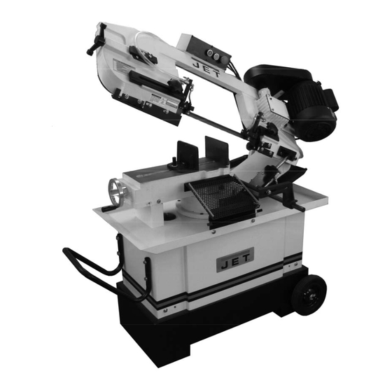
7x10-inch Belt Driven Mitering Band Saw
Model HVBS-710S
WALTER MEIER (Manufacturing) Inc.
427 New Sanford Road
LaVergne, Tennessee 37086
Part No. M-413451
Ph.: 800-274-6848
Revision A 01/2012
www.waltermeier.com
Copyright © 2012 Walter Meier (Manufacturing) Inc.
Advertisement
Table of Contents

Subscribe to Our Youtube Channel
Related Manuals for Jet HVBS-710S


Summary of Contents for Jet HVBS-710S
- Page 1 This .pdf document is bookmarked Operating Instructions and Parts Manual 7x10-inch Belt Driven Mitering Band Saw Model HVBS-710S WALTER MEIER (Manufacturing) Inc. 427 New Sanford Road LaVergne, Tennessee 37086 Part No. M-413451 Ph.: 800-274-6848 Revision A 01/2012 www.waltermeier.com Copyright © 2012 Walter Meier (Manufacturing) Inc.
-
Page 2: Warranty And Service
Authorized Service Centers located throughout the United States can give you quick service. In most cases, any of these Walter Meier Authorized Service Centers can authorize warranty repair, assist you in obtaining parts, or perform routine maintenance and major repair on your JET® tools. For the name of an Authorized Service Center in your area call 1-800-274-6848. -
Page 3: Table Of Contents
12.2 Gear box ..........................20 13.0 Troubleshooting the HVBS-710S ....................21 14.0 Replacement Parts ........................22 14.1.1 HVBS-710S Table and Stand Assembly – Exploded View............. 23 14.1.2 HVBS-710S Bow Assembly – Exploded View............... 24 14.1.3 HVBS-710S Assembly – Parts List ..................25... -
Page 4: Safety Warnings
work in a well-ventilated area and work with approved safety equipment, such as face or dust masks that are specifically designed to filter out microscopic particles. 3.0 Safety Warnings 10. Do not operate this machine while tired or under the influence of drugs, alcohol or any medication. -
Page 5: About This Manual
4.0 About this manual This manual is provided by Walter Meier (Manufacturing) Inc. covering the safe operation and maintenance procedures for a JET Model HVBS-710S Band Saw. This manual contains instructions on installation, safety precautions, general operating procedures, maintenance instructions and parts breakdown. -
Page 6: Features
16. Fixed vise Chip brush 17. Rotating disc hub for miter cuts Hydraulic cylinder with valve regulator 6.0 Specifications Model Number ............................... HVBS-710S Stock Number ................................413451 Materials: Frame ................................cast iron Table ................................cast iron Blade wheels ..............................cast iron Base .................................. - Page 7 Capacities: Miter angle...............................90 to 45 deg. Round capacity at 90° ..........................7” (180 mm) Round capacity at 45° ..........................4” (100 mm) Round capacity at 30° ......................... 6-3/4” (171mm) Rectangle capacity at 90° (W x H) ................7” x 10-13/64” (180 x 260 mm) Rectangle capacity at 45°...
-
Page 8: Set-Up And Assembly
7.0 Set-Up and Assembly Tools required for assembly: 12mm wrench 3, 4, and 6mm hex keys 7.1 Unpacking and cleanup Inspect contents of shipping container for shipping damage. Report any damage to your distributor. Remove all contents from carton, and compare to the contents list in this manual. -
Page 9: Assembly
Figure 4 4. Use properly rated lifting equipment (hoist or 7.3 Assembly forklift) with straps placed beneath cast iron portion of saw. Refer to Figure 4. 5. Position saw atop base and secure with four screws and washers (HP-1/6/7). Band should disconnected from electrical power during 6. -
Page 10: Vertical Cutting Plate
7.4 Vertical cutting plate These steps are only necessary when using band saw in vertical position. 1. Disconnect machine from power source. 2. Open valve on hydraulic cylinder (lever parallel to cylinder) and raise bow to vertical position. 3. Remove two screws and remove seat plate, as shown in Figure 5. -
Page 11: Coolant System
2. Grounded, cord-connected tools intended for injury. use on a supply circuit having a nominal rating The HVBS-710S Band Saw is rated at 115/230V less than 150 volts: power, and pre-wired for 115 volt. The band saw This tool is intended for use on a circuit that has... -
Page 12: Voltage Conversion
The green-colored rigid ear, lug, and the like, extending from the adapter must be connected to a permanent ground such as a properly grounded outlet box. 3. Grounded, cord-connected tools intended for use on a supply circuit having a nominal rating between 150 - 250 volts, inclusive: This tool is intended for use on a circuit that has an outlet that looks like the one illustrated in D,... -
Page 13: Adjustments
9.0 Adjustments The settings on your band saw, such as blade squareness, tension, and tracking were carefully performed by the manufacturer. You should, however, verify these before operating, in case misalignment has occurred during shipping. 9.1 Squaring blade to table 1. -
Page 14: Miter Cuts
9.4 Miter cuts 1. Loosen handle (G, Figure 17). 2. Rotate bow to desired angle up to 45- degrees, using scale indicator on front of base. 3. Tighten handle. Figure 18 9.6 Counterbalance spring The counterbalance spring helps control the amount of weight the saw bow puts on the workpiece when the hydraulic control valve is fully open. -
Page 15: Blade Tension
times. If the teeth of the blade are so far apart the blade has been turned inside-out. Twist that they straddle the work, severe damage to blade right side-out and reinstall.) the workpiece and to the blade can result. 9. Position blade around wheels, making sure 1. -
Page 16: Blade Tracking
TIP: Slacken blade tension when finished with Keep fingers clear of blade operations, to prolong blade life. Make note of and wheel to avoid injury. indicator position on tension label (E, Figure 20) for quickly returning tension to its previous 7. -
Page 17: Setting Blade Speed
Figure 23 Figure 22 Figure 24 The saw blade can be considered correctly adjusted when the variation measure is no more 9.12 Blade guide adjustment than 0.012 inch across the face of the disk. 1. Loosen knobs (A, Figure 25). If you do not have a piece of 2-inch bar stock 2. -
Page 18: Chip Brush
9.14 Limit switch 1. Disconnect machine from power source. 2. Raise bow to vertical and secure in place by The stop screw (F, Figure 28) activates a limit turning off hydraulic cylinder. switch to shut off the saw when it reaches down position. -
Page 19: Operation
Consult the blade manufacturer’s literature for break-in of specific blades on specific materials. Figure 30 However, the following procedure will be adequate for break-in of JET-supplied blades on Never hold a workpiece by lower alloy ferrous materials. hand when cutting it – the workpiece should 1. -
Page 20: Evaluating Cutting Efficiency
10. The machine will shut off at the completion of the cut. Turn off coolant flow and remove workpiece. 11. Return bow to raised position for next cut. 11.4 Evaluating cutting efficiency Is the blade cutting efficiently? The best way to determine this is to observe the chips formed by the cutting blade. -
Page 21: Troubleshooting The Hvbs-710S
7. Reinstall gasket and cover. Fasten cover with screws. Completely drain and refill gear box oil after the first 90 days of operation. Thereafter, change every six months. 13.0 Troubleshooting the HVBS-710S Trouble Probable Cause Remedy Motor will not start. -
Page 22: Replacement Parts
Trouble Probable Cause Remedy Excessive blade Incorrect blade tension. Adjust blade tension. breakage. Incorrect blade speed or downfeed rate. Adjust acccordingly. Workpiece loose in vise. Clamp workpiece securely. Blade rubs on wheel flange. Adjust blade tracking. Use appropriate blade for material being Teeth too coarse for material. -
Page 23: Hvbs-710S Table And Stand Assembly - Exploded View
14.1.1 HVBS-710S Table and Stand Assembly – Exploded View... -
Page 24: Hvbs-710S Bow Assembly - Exploded View
14.1.2 HVBS-710S Bow Assembly – Exploded View... -
Page 25: Hvbs-710S Assembly - Parts List
14.1.3 HVBS-710S Assembly – Parts List Index No. Part No. Description Size 1 ....HVBS710S-1 ....Bottom Pan..................1 1-1 ... TS-0060071 ....Hex Cap Screw ..........3/8" x 1-1/2" ....2 1-2 ..TS-0570031 ....Hex Nut ............3/8" ......2 1-3 ... - Page 26 Index No. Part No. Description Size 53 .... TS-1492041 ....Hex Cap Screw ..........M12 x 40 ....1 54 .... TS-1540081 ....Hex Nut ............M12 ......1 55 .... HVBS710S-55 ..... Splash Guard ................. 1 56 .... TS-0081031 ....Hex Cap Screw ..........5/16" x 3/4"....2 57 ....
- Page 27 Index No. Part No. Description Size 112 ..HVBS710S-112 ... Stop Rod ..................1 114 ..TS-1492031 ....Hex Cap Screw ..........M12 x 35 ....2 115 ..TS-0720111 ....Spring Washer ..........1/2" ......2 116 ..HVBS710S-116 ... Fixed Vise..................1 117 ..
- Page 28 Index No. Part No. Description Size 166 ..HVBS710S-166 ... Socket Head Cap Screw .......5/16" x 1-1/8"....2 166-1 ..TS-0720081 ....Spring Washer ..........5/16" ......2 167 ..HVBS710S-167 ... Connection Tube ................1 168 ..HVBS710S-168 ... Hose ..................... 1 169 ..
- Page 29 ....HVBS710S-LBDA ..Label – Blade Direction Arrow (not shown)........1 ....HVBS710S-ID ..... I.D. Label (not shown) ..............1 ....HVBS710S-HP .... Hardware Package (see contents page 8)........1 ....JETLOGO-1 ....JET Logo .............2-3/4" x 8" ....1 ....STRIPE-1-3/4 ....JET Stripe............1-3/4” ....per ft.
-
Page 30: Electrical Connections For Hvbs-710S
15.0 Electrical Connections for HVBS-710S... - Page 32 WALTER MEIER (Manufacturing) Inc. 427 New Sanford Road LaVergne, Tennessee 37086 Phone: 800-274-6848 www.waltermeier.com...
Need help?
Do you have a question about the HVBS-710S and is the answer not in the manual?
Questions and answers