Table of Contents
Advertisement
This .pdf document is bookmarked
Operating Instructions and Parts Manual
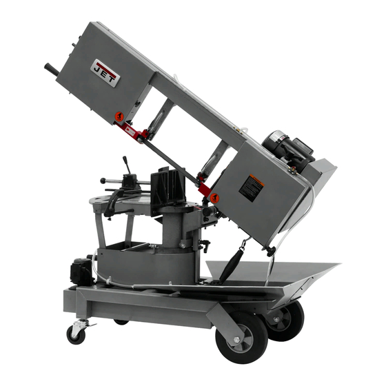
Portable Dual Mitering Band Saws
Models HVBS-8-DMW, HVBS-10-DMW, HVBS-10-DMWC
Model HVBS-10-DMWC shown
JET
427 New Sanford Road
LaVergne, Tennessee 37086
Part No. M-424460
Ph.: 800-274-6848
Edition 1 12/2016
www.jettools.com
Copyright © 2016 JET
1
Advertisement
Table of Contents


Need help?
Do you have a question about the HVBS-10-DMW and is the answer not in the manual?
Questions and answers