Table of Contents
Advertisement
Quick Links
Operating Instructions and Parts Manual
Portable Dual Mitering Band Saws
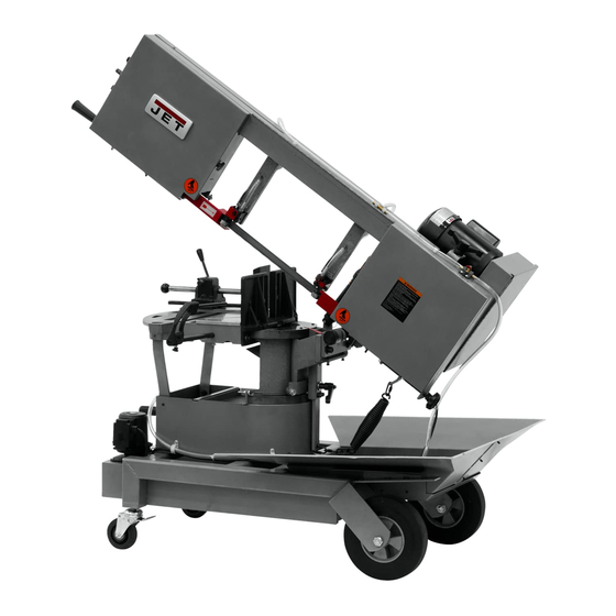
Models HVBS-8-DMW, HVBS-10-DMW, HVBS-10-DMWC
JET
427 New Sanford Road
LaVergne, Tennessee 37086
Ph.: 800-274-6848
www.jettools.com
Model HVBS-10-DMWC shown
For HVS-8-DMW after serial no. 1701BG00017
For HVS-10-DMW after serial no. 1701BK00017
1
This .pdf document is bookmarked
Part No. M-424460
Edition 8 06/2020
Copyright © 2017 JET
Advertisement
Table of Contents

Related Manuals for Jet HVS-8-DMW


Summary of Contents for Jet HVS-8-DMW
- Page 1 This .pdf document is bookmarked Operating Instructions and Parts Manual Portable Dual Mitering Band Saws Models HVBS-8-DMW, HVBS-10-DMW, HVBS-10-DMWC Model HVBS-10-DMWC shown For HVS-8-DMW after serial no. 1701BG00017 For HVS-10-DMW after serial no. 1701BK00017 427 New Sanford Road LaVergne, Tennessee 37086 Part No. M-424460 Ph.: 800-274-6848...
-
Page 2: Important Safety Instructions
Do not use this machine for other than its intended use. If used for other purposes, JET 20. Maintain a balanced stance at all times so that disclaims any real or implied warranty and holds... -
Page 3: On-Off Switch Padlock
29. Never hand hold the material. Always use the WARNING: This product can expose you to vise and clamp it securely. chemicals including titanium dioxide which is 30. Be sure that blade is not in contact with known to the State of California to cause cancer, workpiece when motor is started. -
Page 4: Table Of Contents
2.0 Table of contents Section Page 1.0 IMPORTANT SAFETY INSTRUCTIONS ....................... 2 1.1 On-off switch padlock ..........................3 2.0 Table of contents ............................4 3.0 About this manual ............................5 4.0 Specifications for HVBS-DMW series Band Saws ..................6 ... -
Page 5: About This Manual
If there are questions or comments, please contact your local supplier or JET. JET can also be reached at our web site: www.jettools.com. -
Page 6: Specifications For Hvbs-Dmw Series Band Saws
4.0 Specifications for HVBS-DMW series Band Saws Model number HVBS-8-DMW HVBS-10-DMW HVBS-10-DMWC Stock number 424460 424463 424465 Motor and Electricals Motor type TEFC induction Horsepower 3/4 HP (0.56 kW) 1 HP (0.75 kW) 1 HP (0.75 kW) Phase Voltage 115 / 230V (prewired 115V) Cycle 60 Hz Listed FLA (full load amps) - Page 7 = not applicable The specifications in this manual were current at time of publication, but because of our policy of continuous improvement, JET reserves the right to change specifications at any time and without prior notice, without incurring obligations.
-
Page 8: Setup And Assembly
If closer reach is needed toward blade, insert 5.0 Setup and assembly small rod (A ) and tighten with wrench on rod flat. Read understand instructions before attempting assembly. Band Saw must be disconnected from power during all assembly procedures. Failure to comply may cause serious injury. -
Page 9: Grounding Instructions
circuit with a grounded outlet that looks like the one grounded outlet can be installed by a qualified pictured in A, Figure 6-1. electrician. The green-colored rigid ear, lug, and the like, extending from the adapter must be connected Before connecting to power source, be sure switch to a permanent ground such as a properly grounded is in off position. -
Page 10: Extension Cords
The plug on end of power cord must be replaced with a UL/CSA listed plug rated for 230 volt operation. 6.3 Extension cords The use of extension cords is discouraged; try to position machines near the power source. If an extension cord is necessary, make sure it is in good condition. -
Page 11: Blade Guide Arms
that they straddle the work, severe damage to workpiece and blade can result. Disconnect band saw from power source. Raise bow to convenient position. Open wheel guards and prop them open with the attached rods (G, Figure 7-5). Remove red blade guards (H). -
Page 12: Blade Guide Bearings
Install red blade guards. Return blade guide arm to operating position. Tension blade fully (see sect. 7.7) Note: A new blade should be re-checked for proper tension after a few minutes’ operation. 10. Place two to three drops of lightweight oil on 7.7.2 Tracking blade. -
Page 13: Blade-To-Table Squareness
10. Once tracking is set, tighten hex nuts (N With bar stock securely clamped in vise, make a cut through the bar stock. (See Figure 7-10.) Mark the top of bar stock. Move the bar stock about 1/4-inch past the blade so that you can begin a second cut. -
Page 14: Counterbalance Spring
7.11 Vertical bow position To close hydraulic flow, turn lever (R ) down, perpendicular to cylinder, as shown. To open Disconnect band saw from power source. hydraulic flow, turn lever (R ) parallel to cylinder. Position bow at 90-degrees (zero swivel). Feed rate is adjusted by operator until saw is operating efficiently,... -
Page 15: Vise Positioning
Consult the blade manufacturer’s literature for break-in of specific blades on specific materials. However, the Figure 7-15: floating vise jaw following procedure will be adequate for break-in of JET-supplied blades lower alloy ferrous 7.14 Work stop materials. -
Page 16: General Operating Procedure
8.3 General operating procedure IMPORTANT: When cutting magnesium, never use soluble oils or emulsions (oil-water mix) as water will greatly intensify any accidental magnesium chip fire. See your industrial coolant supplier for specific coolant recommendations when cutting such material. Give machine an overall inspection. Verify that all guards, covers, etc. -
Page 17: User-Maintenance
9.0 User-maintenance To change gear box oil: Disconnect machine from power source. Place bow in horizontal position and allow a few Always disconnect power to moments for oil to settle. machine before performing maintenance. Failure to do this may result in serious personal Remove drain plug (A, Figure 9-1) and drain oil injury. -
Page 18: Troubleshooting Hvbs-Dm Series Band Saws
10.0 Troubleshooting HVBS-DM series Band Saws Symptom Possible Cause Correction* Excessive blade Material loose in vise. Clamp work securely. breakage Incorrect speed or feed. Check machinery handbook for speed/ feed appropriate for material being cut. Teeth too coarse for material. Check machinery handbook for recommended blade type. -
Page 19: Replacement Parts
Non-proprietary parts, such as fasteners, can be found at local hardware stores, or may be ordered from JET. Some parts are shown for reference only, and may not be available individually. -
Page 20: Hvbs-8-Dmw Bow Assembly - Exploded View
11.1.1 HVBS-8-DMW Bow Assembly – Exploded View Figure 11-1... -
Page 21: Hvbs-8-Dmw Table Assembly - Exploded View
11.1.2 HVBS-8-DMW Table Assembly – Exploded View Figure 11-2... -
Page 22: Hvbs-8-Dmw Motor And Support Arm Assembly - Exploded View
11.1.3 HVBS-8-DMW Motor and Support Arm Assembly – Exploded View Figure 11-3... -
Page 23: Hvbs-8-Dmw Vise And Table Assembly - Exploded View
11.1.4 HVBS-8-DMW Vise and Table Assembly – Exploded View Figure 11-4 11.1.5 HVBS-8-DMW Base Assembly – Exploded View Figure 11-5... -
Page 24: Hvbs-8-Dmw - Parts List
11.1.6 HVBS-8-DMW – Parts List Index No Part No Description Size 1 ....HVBS-8-DMW-1 .... Saw Bow ....................1 1-1 ..... TS-1490091 ....Hex Cap Bolt ............M8-1.25x45L ... ………...1 1-2 ..... TS-1524051 ....Set Screw ............. M8-1.25x20L ....2 1-3 ..... - Page 25 Index No Part No Description Size 28 ....HVBS-8-DMW-28 ..Movable Guide Block ................. 1 28-1 ... TS-1503061 ....Hex Socket Cap Screw ........M6-1.0x25L ....4 28-2 ... TS-1550041 ....Flat Washer ............6mm ......4 28-3 ... TS-1504041 ....Hex Socket Cap Screw ........M8-1.25x20L ....2 28-4 ...
- Page 26 Index No Part No Description Size ....HVBS-8-DMW-45JB ..Junction Box ....................1 ....HVBS-8-DMW-45JBC ... Junction Box Cover ..................1 ....HVBS-8-DMW-45MF ..Motor Fan ....................1 ....HVBS-8-DMW-45MFC .. Motor Fan Cover ..................1 46 ....
- Page 27 89-4 ... TS-1490051 ....Hex Cap Bolt…............ M8-1.25x30L ....1 89-5 ... TS-0680041 ....Flat Washer ............3/8" ........ 1 89-6 ... TS-1540061 ....Hex Nut ..............M8-1.25 ......1 ....JET-138 ......JET Logo (not shown) .......... 138x57mm ....1...
- Page 28 Index No Part No Description Size ....LM000268 ..... ID Label, HVBS-8DMW (not shown) ............1 ....LM000269 ..... Label, Blade Speeds (not shown) .............. 1 ....LM000271 ..... Warning Label (not shown) ................ 1...
-
Page 29: Hvbs-10-Dmw/Dmwc Bow Assembly - Exploded View
11.2.1 HVBS-10-DMW/DMWC Bow Assembly – Exploded View Figure 11-6... -
Page 30: Hvbs-10-Dmw/Dmwc Table Assembly - Exploded View
11.2.2 HVBS-10-DMW/DMWC Table Assembly – Exploded View Figure 11-7... -
Page 31: Hvbs-10-Dmw/Dmwc Motor And Support Arm Assembly - Exploded View
11.2.3 HVBS-10-DMW/DMWC Motor and Support Arm Assembly – Exploded View Figure 11-8... -
Page 32: Hvbs-10-Dmw/Dmwc Vise And Table Assembly - Exploded View
11.2.4 HVBS-10-DMW/DMWC Vise and Table Assembly – Exploded View Figure 11-9... -
Page 33: Hvbs-10-Dmw/Dmwc Base Assembly - Exploded View
11.2.5 HVBS-10-DMW/DMWC Base Assembly – Exploded View Figure 11-10... -
Page 34: Hvbs-10-Dmw/Dmwc - Parts List
11.2.6 HVBS-10-DMW/DMWC – Parts List Index No Part No Description Size 1 ....HVBS-10-DMW-1 ..Saw Bow ....................1 1-1 ..... HVBS-10-DMW-1-1 ..Stop Screw ....................1 1-2 ..... TS-0570021 ....Hex Nut ..............5/16"-18NC ....2 1-3 ..... TS-1490081 ....Hex Cap Bolt ............M8-1.25x45L ....1 1-4 ..... - Page 35 Index No Part No Description Size 21 ....HVBS-10-DMW-21 ..Strain Relief ............PG-9 ......7 22 ....HVBS-10-DMW-22 ..Limit Switch ....................1 22-1 ... F001187 ......Phillips Pan Hd Machine Screw ......M4-0.7x25L ....2 22-2 ... TS-1540021 ....Hex Nut ..............M4-0.7 ......2 23 ....
- Page 36 Index No Part No Description Size 43-3 ... HVBS-8-DMW-37 ..Collar ......................1 43-4 ... TS-2361061 ....Lock Washer ............M6 ......... 2 44 ....TS-1482021 ....Hex Cap Bolt ............M6-1.0x12L ....4 44-1 ... TS-2361061 ....Lock Washer ............M6 ......... 4 44-2 ...
- Page 37 Index No Part No Description Size 68-2 ... TS-2361081 ....Lock Washer ............M8 ......... 4 68-3 ... TS-1550061 ....Flat Washer ............8x18x2 mm ....4 69 ....TS-1504071 ....Hex Socket Cap Screw ........M8-1.25x35L ....2 70 ....TS-1550061 ....Flat Washer ............8x25x3 mm ....2 70-1 ...
- Page 38 101-6 ..TS-1550031 ....Flat Washer ............5mm ......2 102 .... HVBS-10-DMW-102 ..PU Hose (not shown) ........... 5/16" x 5ft...... 1 ....JET-138 ......JET Logo (not shown) .......... 138x57mm ....1 ....LM000270 ..... ID Label, HVBS-10DMW (not shown) ............1 ....
-
Page 39: Electrical Connections For Hvbs-Dmw Band Saws
12.0 Electrical Connections for HVBS-DMW Band Saws Figure 12-1... -
Page 40: Warranty And Service
JET sells through distributors only. The specifications listed in JET printed materials and on official JET website are given as general information and are not binding. JET reserves the right to effect at any time, without prior notice, those alterations to parts, fittings, and accessory equipment which they may deem necessary for any reason whatsoever.
Need help?
Do you have a question about the HVS-8-DMW and is the answer not in the manual?
Questions and answers