Table of Contents
Advertisement
This .pdf document is bookmarked
Operating Instructions and Parts Manual
7x10-inch Gear Head Mitering Band Saw
Model HVBS-710SG
WALTER MEIER (Manufacturing) Inc.
427 New Sanford Road
LaVergne, Tennessee 37086
Part No. M-413452
Ph.: 800-274-6848
Revision A1 11/2012
www.waltermeier.com
Copyright © 2012 Walter Meier (Manufacturing) Inc.
Advertisement
Table of Contents

Subscribe to Our Youtube Channel
Related Manuals for Jet HVBS-710SG


Summary of Contents for Jet HVBS-710SG
- Page 1 This .pdf document is bookmarked Operating Instructions and Parts Manual 7x10-inch Gear Head Mitering Band Saw Model HVBS-710SG WALTER MEIER (Manufacturing) Inc. 427 New Sanford Road LaVergne, Tennessee 37086 Part No. M-413452 Ph.: 800-274-6848 Revision A1 11/2012 www.waltermeier.com Copyright © 2012 Walter Meier (Manufacturing) Inc.
-
Page 2: Warranty And Service
Authorized Service Centers located throughout the United States can give you quick service. In most cases, any of these Walter Meier Authorized Service Centers can authorize warranty repair, assist you in obtaining parts, or perform routine maintenance and major repair on your JET® tools. For the name of an Authorized Service Center in your area call 1-800-274-6848. -
Page 3: Table Of Contents
12.2 Gear box ..........................20 13.0 Troubleshooting the HVBS-710SG .................... 21 14.0 Replacement Parts ........................22 14.1.1 HVBS-710SG Table and Stand Assembly – Exploded View ..........23 14.1.2 HVBS-710SG Bow Assembly – Exploded View ..............24 14.1.3 HVBS-710SG Assembly – Parts List..................25 14.2.1 HVBS-710SG Gearbox Assembly –... -
Page 4: Safety Warnings
dust masks that are specifically designed to filter out microscopic particles. 10. Do not operate this machine while tired or under the influence of drugs, alcohol or any 3.0 Safety Warnings medication. 11. Make certain the switch is in the OFF 1. -
Page 5: About This Manual
4.0 About this manual This manual is provided by Walter Meier (Manufacturing) Inc. covering the safe operation and maintenance procedures for a JET Model HVBS-710SG Band Saw. This manual contains instructions on installation, safety precautions, general operating procedures, maintenance instructions and parts breakdown. -
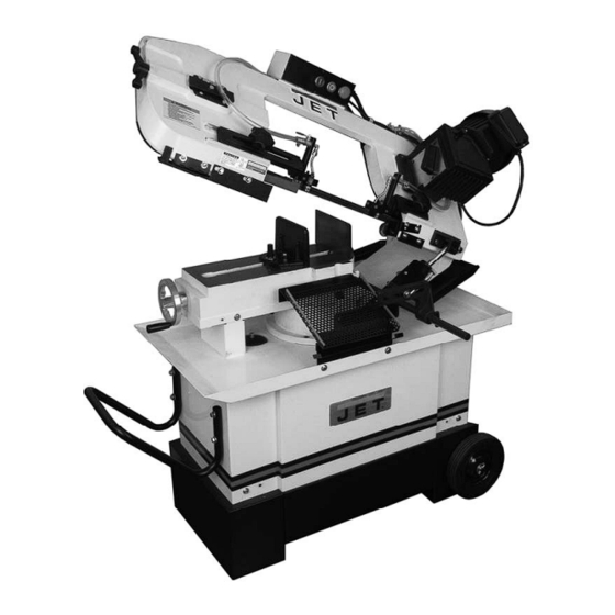
Page 6: Features
16. Fixed vise Chip brush 17. Rotating disc hub for miter cuts Hydraulic cylinder with valve regulator 6.0 Specifications Model Number ............................HVBS-710SG Stock Number ................................413452 Materials: Frame ................................cast iron Table ................................cast iron Blade wheels ..............................cast iron Base .................................. - Page 7 Capacities: Miter angle...............................90 to 45 deg. Round capacity at 90° ..........................7” (180 mm) Round capacity at 45° ..........................4” (100 mm) Round capacity at 30° .......................... 6-3/4”(171mm) Rectangle capacity at 90° (W x H) ................7” x 10-13/64” (180 x 260 mm) Rectangle capacity at 45°...
-
Page 8: Set-Up And Assembly
7.0 Set-Up and Assembly Tools required for assembly: 12mm wrench 3, 4, and 6mm hex keys 7.1 Unpacking and cleanup Inspect contents of shipping container for shipping damage. Report any damage to your distributor. Remove all contents from carton, and compare to the contents list in this manual. -
Page 9: Assembly
Figure 4 4. Use properly rated lifting equipment (hoist or 7.3 Assembly forklift) with straps placed beneath cast iron portion of saw. Refer to Figure 4. 5. Position saw atop base and secure with four screws and washers (HP-1/6/7). Band should disconnected from electrical power during 6. -
Page 10: Vertical Cutting Plate
7.4 Vertical cutting plate These steps are only necessary when using band saw in vertical position. 1. Disconnect machine from power source. 2. Open valve on hydraulic cylinder (lever parallel to cylinder) and raise bow to vertical position. 3. Remove two screws and remove seat plate, as shown in Figure 5. -
Page 11: Coolant System
150 volts: The HVBS-710SG Band Saw is rated at This tool is intended for use on a circuit that has 115/230V power, and pre-wired for 115 volt. The... -
Page 12: Voltage Conversion
to a permanent ground such as a properly grounded outlet box. 3. Grounded, cord-connected tools intended for use on a supply circuit having a nominal rating between 150 - 250 volts, inclusive: This tool is intended for use on a circuit that has an outlet that looks like the one illustrated in D, Figure 11. -
Page 13: Adjustments
9.0 Adjustments The settings on your band saw, such as blade squareness tracking, were carefully performed by the manufacturer. You should, however, verify these before operating, in case misalignment has occurred during shipping. 9.1 Squaring blade to table 1. Disconnect machine from power source. 2. -
Page 14: Miter Cuts
9.4 Miter cuts 1. Loosen handle (G, Figure 17). 2. Rotate bow to desired angle up to 45- degrees, using scale indicator on front of base. 3. Tighten handle. Figure 18 9.6 Counterbalance spring The counterbalance spring helps control the amount of weight the saw bow puts on the workpiece when the hydraulic control valve is fully open. -
Page 15: Blade Tension
that they straddle the work, severe damage to 9. Position blade around wheels, making sure the workpiece and to the blade can result. it rests near the flange on both wheels. 1. Disconnect machine from power source. 10. Tension blade using handle. Do not over- tension. -
Page 16: Blade Tracking
for quickly returning tension to its previous Keep fingers clear of blade setting. and wheel to avoid injury. 9.9 Blade tracking 7. Turn set screw to stop shifting of blade on the wheel as it gets closer to wheel flange. Put a six-inch length of paper between blade Tracking the blade requires and wheel. -
Page 17: Setting Blade Speed
Material chips or shavings are the best indicator of proper blade speed and downfeed rate. See section 11.4, Evaluating cutting efficiency. 9.12 Blade guide adjustment 1. Loosen knobs (A, Figure 24). 2. Slide guide assemblies close workpiece as possible, without interfering with the cut. -
Page 18: Chip Brush
6. Tighten nut (C). 7. Repeat for other blade guide assembly. Figure 27 10.0 Operating controls Figure 25 To start saw, push On button (A, Figure 28). To stop saw before it reaches the end of cut, push Off button (B). The saw will automatically stop at the end of a cut. -
Page 19: Operation
Consult the blade manufacturer’s literature for Figure 29 break-in of specific blades on specific materials. However, the following procedure will be adequate for break-in of JET-supplied blades on Never hold a workpiece by lower alloy ferrous materials. hand when cutting it – the workpiece should be firmly secured in the vise. -
Page 20: Evaluating Cutting Efficiency
11.4 Evaluating cutting efficiency Is the blade cutting efficiently? The best way to determine this is to observe the chips formed by the cutting blade. If chip formation is powdery, then the feed rate is much too light, or the blade is dull. If chips formed are curled, but colored —... -
Page 21: Troubleshooting The Hvbs-710Sg
Periodically, after draining remove screws, cover and gasket, and wipe out residual oil from gearbox interior with a rag, before refilling. Also do this if changing oil brands. 13.0 Troubleshooting the HVBS-710SG Trouble Probable Cause Remedy Motor will not start. -
Page 22: Replacement Parts
Trouble Probable Cause Remedy Excessive blade Blade guides are misaligned. Adjust blade guides as needed. breakage (cont.) Blade too thick for wheel diameter. Use thinner blade. Cracking at weld; poor annealing of blade. Replace blade. Premature blade Teeth too coarse. Use finer tooth blade. -
Page 23: Hvbs-710Sg Table And Stand Assembly - Exploded View
14.1.1 HVBS-710SG Table and Stand Assembly – Exploded View... -
Page 24: Hvbs-710Sg Bow Assembly - Exploded View
14.1.2 HVBS-710SG Bow Assembly – Exploded View... -
Page 25: Hvbs-710Sg Assembly - Parts List
14.1.3 HVBS-710SG Assembly – Parts List Index No. Part No. Description Size 1 ....HVBS710S-1 ....Bottom Pan..................1 1-1 ... TS-0060071 ....Hex Cap Screw ..........3/8" x 1-1/2" ....2 1-2 ..TS-0570031 ....Hex Nut ............3/8" ......2 1-3 ... - Page 26 Index No. Part No. Description Size 53 .... TS-1492041 ....Hex Cap Screw ..........M12 x 40 ....1 54 .... TS-1540081 ....Hex Nut ............M12 ......1 55 .... HVBS710S-55 ..... Splash Guard ................. 1 56 .... TS-0081031 ....Hex Cap Screw ..........5/16" x 3/4"....2 57 ....
- Page 27 Index No. Part No. Description Size 112 ..HVBS710S-112 ... Stop Rod ..................1 114 ..TS-1492031 ....Hex Cap Screw ..........M12 x 35 ....2 115 ..TS-0720111 ....Spring Washer ..........1/2" ......2 116 ..HVBS710S-116 ... Fixed Vise Jaw ................1 117 ..
- Page 28 Index No. Part No. Description Size 164 ..HVBS710S-164 ... Nozzle Cock Support ..............2 165 ..TS-0267051 ....Socket Set Screw .........1/4" x 1/2" ....2 166 ..HVBS710S-166 ... Socket Head Cap Screw .......5/16" x 1-1/8"....2 166-1 ..TS-0720081 ....Spring Washer ..........5/16" ......2 167 ..
- Page 29 210 ..HVBS710S-LBDA ..Label – Blade Direction Arrow (not shown)........1 211 ..HVBS710SG-ID ... I.D. Label (not shown) ..............1 ....HVBS710S-HP .... Hardware Package (see contents page 8)........1 ....JETLOGO-1 ....JET Logo .............2-3/4" x 8" ....1 ....STRIPE-1-3/4 ....JET Stripe............1-3/4” ....per ft.
-
Page 30: Hvbs-710Sg Gearbox Assembly - Exploded View
14.2.1 HVBS-710SG Gearbox Assembly – Exploded View... -
Page 31: Hvbs-710Sg Gearbox Assembly - Parts List
14.2.2 HVBS-710SG Gearbox Assembly – Parts List Index No. Part No. Description Size ....HVBS710SG-196-1..Gearbox Assembly (index #1 thru 42) ..........1 1 ....HVBS710SG-129..Vent Plug..................1 2 ....TS-1503051 ....Socket Head Cap Screw .......M6 x 20 ...... 5 3 .... -
Page 32: Electrical Connections For Hvbs-710Sg
15.0 Electrical Connections for HVBS-710SG...
Need help?
Do you have a question about the HVBS-710SG and is the answer not in the manual?
Questions and answers