
Subscribe to Our Youtube Channel
Related Manuals for Baxi Barcelona System


Summary of Contents for Baxi Barcelona System
- Page 1 Please leave these Instructions with the User Baxi Barcelona System Wall Mounted Powered Flue Condensing Boiler Gas Fired Central Heating Unit Comp N 243612 - Iss 5 - 4/00 Installation and Servicing Instructions...
- Page 2 Directive 92/42/EEC on the energy efficiency requirements for new hot water boilers fired with liquid or gaseous fuels:- We hope you get a satisfactory service from Baxi. If not, please let us know. Type test for purpose of Regulation 5 certified by: Notified Body 0086.
-
Page 3: Table Of Contents
Contents - Page 3 Section Page Introduction General Layout Appliance Operation Technical Data Dimensions and Fixings System Details Site Requirements Installation Electrical 10.0 Commissioning the Boiler 11.0 Fitting the Outer Case 12.0 Servicing the Boiler 13.0 Changing Components 14.0 Fault Finding 15.0 Short Parts List... -
Page 4: Introduction
Read the instructions fully before installing or using the appliance. 1.1 Description 1. The Baxi Barcelona System is a gas fired room sealed fan assisted condensing central heating system boiler. 2. The maximum output of the boiler is preset at 80,000 Btu/hr. -
Page 5: General Layout
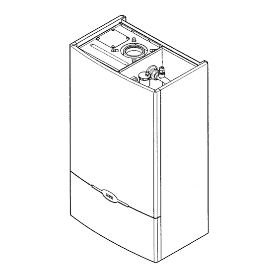
General Layout - Page 5 2.1 Layout (Figs. 3,4 & 5) Wall Plate Flue Elbow Heat Exchanger Burner Air Box Fan Protection Thermostat Fan Assembly Condensate Trap User Interface (optional timer available) 10. Gas Tap 11. Gas / Air Ratio Valve 12. -
Page 6: Appliance Operation
Appliance Operation - Page 6 1. Pump Overrun: When the switched live to the boiler switches on or the flow temperature is greater than the set point or anti-cycle finishes then Pump Overrun occurs for 10 seconds (cold) or 60 seconds (hot). The pump is on while the fan, spark generator and gas valve are off. -
Page 7: Technical Data
Technical Data - Page 7... -
Page 8: Dimensions And Fixings
Dimensions and Fixings - Page 8... -
Page 9: System Details
It is important to check the inhibitor concentration after installation, system modification and at every service in accordance with the manufacturer’s instructions. (Test kits are available from inhibitor stockists.) • For information or advice regarding any of the above contact the Baxi Helpline. - Page 10 4. Operation of the system under control of the boiler thermostat & TRV’s only does not produce the best results. 6.5 Thermal Stores 1. The Barcelona System Boiler must not be fitted to thermal stores which override the boiler control system.
- Page 11 6.0 System Details - Page 11 6.6 System Filling and Pressurising 1. A filling point connection on the central heating return pipework must be provided to facilitate initial filling and pressurising and also any subsequent water loss replacement/refilling. 2. The filling method adopted must be in accordance with all relevant water supply bye-laws and use approved equipment.
-
Page 12: Site Requirements
WARNING - The addition of anything that may interfere with the normal operation of the appliance without the express written permission of Baxi Limited could invalidate the appliance warranty and infringe the GAS SAFETY (Installation and Use) REGULATIONS. - Page 13 7.0 Site Requirements - Page 13 7.5 Ventilation of Compartments (Fig. 14) 1 Where the boiler is installed in a cupboard or compartment, air vents are required (for cooling purposes) in the cupboard or compartment at high and low level which may communicate with a room or direct to outside air.
- Page 14 7.0 Site Requirements - Page 14 7.9 Flue NOTE: Due to the nature of the boiler a plume of water vapour will be discharged from the flue. This should be taken into account when siting the flue terminal. 1. The following guidelines indicate the general requirements for siting balanced flue terminals.
- Page 15 4. The flue terminal guard should be positioned centrally over the terminal and fixed as Illustrated. 7.12 Vertical Flue 1. Only a flue approved with the Baxi Barcelona can be used. 2. For information on vertical flues consult the Baxi Barcelona Installer Guide or Notes for Guidance supplied with the vertical flue pack.
- Page 16 Site Requirements - Page 16 7.13 Flue Options 1. The Baxi Barcelona System can be fitted with flue systems as illustrated. 2. The standard flue is suitable only for horizontal applications. 3. Maximum permissible equivalent flue lengths are:- Horizontal 4.0 metres Vertical 4.0 metres...
-
Page 17: Installation
Installation - Page 17 Check Site Requirements (section 7.0) before commencing. 8.1 Initial Preparation The gas supply, gas type and pressure must be checked for suitability before connection (see Section 7.6). NOTE: If the boiler is to be pre-plumbed, follow both these instructions and those on the boiler pack. - Page 18 5. Stand the boiler on its base by using the rear lower edge as a pivot. NOTE: A small amount of water may drain from the boiler in the upright position. Baxi Limited declare that no substances harmful to health are contained in the appliance or used during construction of the appliance.
- Page 19 Installation - Page 19 8.4 Fitting The Boiler (Fig. 24) 1. Remove the tape from the tap rail on the support bracket and fit the central heating return filter (Fig. 25). 2. Lift the boiler using the lower edges of the combustion box.
- Page 20 Installation - Page 20 8.6 Fitting The Flue Before fitting the flue, check the condensate drain integrity (see section 8.5). IMPORTANT: The flue should always be installed with a (1 in 20) fall from terminal to elbow, to allow condensate to run back to the boiler. HORIZONTAL FLUE 1.
- Page 21 (Fig. 30). If necessary fit a terminal guard (see section 7.11). VERTICAL FLUEING 1. Only a flue approved with the Baxi Barcelona System Boiler can be used. 2. For information on vertical flues consult the Baxi Gas Central Heating Boilers Installer Guide or Notes for Guidance supplied with the vertical flue pack.
- Page 22 Installation - Page 22 8.7 Making The Electrical Connections WARNING: This appliance must be earthed 1. The electrical connections are on the left hand side of the unit behind the facia inside the electrical box. 2. Undo the two screws securing the electrical box cover and remove the cover (Fig.
-
Page 23: Electrical
Electrical - Page 23... - Page 24 9.0 Electrical - Page 24 9.2 Illustrated Wiring Diagram...
-
Page 25: Commissioning The Boiler
10.0 Commissioning the Boiler - Page 25 10.1 Commissioning the Boiler 1. Reference should be made to BS 5449 Section 5 when commissioning the boiler. 2. Flush the whole system using a suitable flushing agent (see Section 6.2) and vent the radiators. Check for water leaks. -
Page 26: Fitting The Outer Case
11.0 Fitting the Outer Case - Page 26 11.1 Fitting The Outer Case 1. Position the outercase on the chassis, ensuring that the four slots in the side flanges align with the hooks on the chassis (Fig. 36). 2. Insert the two fixing screws into the sides of the chassis (Fig. -
Page 27: Servicing The Boiler
PCB remains live. Therefore it is important to isolate the electrical supply. Hazardous materials are not used in the construction of Baxi products, however reasonable care during service is recommended. When replacing the combustion box door after servicing it is essential that the retaining screws are tightened fully. - Page 28 12.0 Servicing the Boiler - Page 28 12.1 Annual Servicing (Cont) 11. If CO/CO ratio is greater than 0.02 then proceed as follows to allow removal and cleaning of inner and rear heat exchanger flueways: a) Disconnect the electrical leads to the fan component protection sensor (Fig.
-
Page 29: Changing Components
PCB remains live. Therefore it is important to isolate the electrical supply. Hazardous materials are not used in the construction of Baxi products, however reasonable care during service is recommended. When replacing the combustion box door after changing components it is essential that the retaining screws are tightened fully. - Page 30 13.0 Changing Components - Page 30 13.3 Flowswitch (Fig. 46) 1. Drain the boiler (see Section 13.1 paragraph 2 & 3). 2. It may be necessary to remove the expansion vessel (see Section 13.5). 3. Remove the clip securing the flow pipe to the flowswitch. 4.
- Page 31 13.0 Changing Components - Page 31 The Pump, interface PCB, pressure gauge and pressure relief valve can be accessed after hinging down the facia box. 1. Release the facia securing screws (¼ turn) and hinge down the facia box. 13.7 Pump (Fig.
- Page 32 13.0 Changing Components - Page 32 13.10 Interface PCB 1. Pull the control knob off the spindle and remove the securing nut and washer (Fig. 53). 2. Lift the PCB from the facia box and remove the electrical connections (Fig. 54). 3.
- Page 33 13.0 Changing Components - Page 33 The control and ignition boards can be accessed on the removal of the main electrical box cover. 1. Remove the two screws securing the main electrical box cover (Fig. 59). 13.13 Control Board (Fig. 60) 1.
- Page 34 13.0 Changing Components - Page 34 The fan and venturi, gas valve, injector pipe, condensate trap, fan protection sensor, spark and sensing electrodes can be accessed and changed on the removal of the airbox door panel. 1. Remove the airbox door panel by loosening the four ¼ turn screws (Fig.
- Page 35 13.0 Changing Components - Page 35 The removal of the fan is necessary to enable the changing of the injector pipe, condensate trap and gas valve (see section 13.17). 13.18 Injector Pipe (Fig. 66) 1. Remove the injector pipe by pulling out from the ‘O’ ring joint in the gas valve.
- Page 36 13.0 Changing Components - Page 36 The burner and heat exchanger can be changed after removal of the combustion box door. To change the heat exchanger, the fan and burner must be removed first (see section 13.17 & 13.21). 1. Remove the combustion box door by removing the four securing screws (Fig.
- Page 37 13.0 Changing Components - Page 37 13.23 Heat Exchanger Lower Insulation Pad (Fig. 73) 1. Remove all components in the base of the airbox. 2. Remove the burner (see section 13.21). 3. Remove the four bolts securing the combustion box base. 4.
-
Page 38: Fault Finding
14.0 Fault Finding - Page 38... - Page 39 14.0 Fault Finding - Page 39...
- Page 40 14.0 Fault Finding - Page 40...
- Page 41 14.0 Fault Finding - Page 41...
- Page 42 14.0 Fault Finding - Page 42...
- Page 43 14.0 Fault Finding - Page 43...
- Page 44 Barcelona System Baxi Heating Ltd. 14.0 Fault Finding- Page 44 - 45 44 - 45...
-
Page 46: Short Parts List
Barcelona System Baxi Heating Ltd. 15.0 Short Parts List - Page 46 Short Parts List G.C. Description Manufacturers Part No. E06 058 Flow Temperature 242458 Thermistor (Red) E06 059 Flow Switch 242459 E06 060 Safety Thermostat (Black) 242460 E06 064...
Need help?
Do you have a question about the Barcelona System and is the answer not in the manual?
Questions and answers