Table of Contents
Advertisement
Quick Links
Technical information
Installation instructions
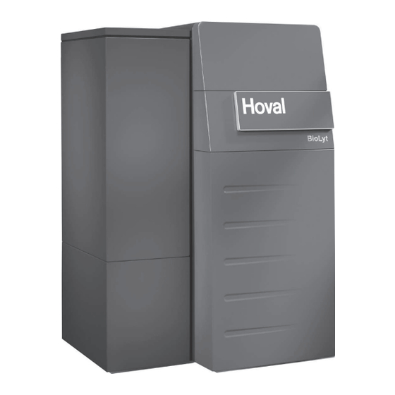
BioLyt (8-36)
Wood pellet boiler
Hoval products must be installed and commissioned
by specialists. These instructions are intended for the
specialist. Electrical installation must be performed by
a licensed electrician.
Subject to modifi cations
|
4 211 326 / 01 - 09/12
These instructions apply to the following
models:
30-BioLyt (8)
30-BioLyt (13)
30-BioLyt (15)
30-BioLyt (23)
30-BioLyt (25)
30-BioLyt (31)
30-BioLyt (36)
7.9 kW
13.0 kW
14.9 kW
23.0 kW
24.9 kW
31.0 kW
36.0 kW
EN
Advertisement
Table of Contents

Subscribe to Our Youtube Channel
Related Manuals for Hoval 30-BioLyt 8


Summary of Contents for Hoval 30-BioLyt 8
- Page 1 24.9 kW 30-BioLyt (31) 31.0 kW 30-BioLyt (36) 36.0 kW Hoval products must be installed and commissioned by specialists. These instructions are intended for the specialist. Electrical installation must be performed by a licensed electrician. Subject to modifi cations 4 211 326 / 01 - 09/12...
-
Page 2: Table Of Contents
TABLE Of COnTEnTS Important notes On delivery ...................................4 Warranty and liability ................................4 Instructions ..................................4 Approvals and identification ...............................4 Regulations, official approvals ............................4 Key to symbols used ................................4 Standards and directives ..............................5 1.7.1 Germany § ..................................5 1.7.2 Switzerland § ..................................5 1.7.3 Austria §... - Page 3 TABLE Of COnTEnTS Commissioning Water quality ..................................35 5.1.1 Heating water..................................35 5.1.2 Filling and replacement water ............................35 filling up the heating system, the calorifier (if fitted) and hot water buffer storage tank..........36 Commissioning ..................................36 Installation inspection ...............................36 Maintenance Cleaning the boiler ................................37 Annual maintenance by the heating engineer ........................37 6.2.1 Heating system ................................37...
-
Page 4: Important Notes
Warns of danger to machines and systems. Instructions You will find all instructions relevant to your system § compiled in the Hoval system manual - please retain all Provides important information. Refers you to instructions for future reference! standards and directives. -
Page 5: Standards And Directives
IMpORTAnT nOTES 1.7.3 Austria § Standards and directives 1.7.1 Germany § ÖNORM H5151-1 Design of hot water central heating systems with or without water heating. EnEV Energy conservation ordinance in the ÖNORM H5170 Heating systems - Requirements current version. with respect to building and safety 1.BimSchV 1st Act for the implementation of technology, fire and environmental... -
Page 6: Characteristics Of The Boiler Room
InSTALLATIOn 2.2.1 Installation Installation modular system, lightweight compact Characteristics of the boiler room components and the carrying aids provided make The architectural and ventilation requirements for boiler installation extremely easy. rooms are defined in the building regulations applicable to the relevant installation site. For overall unit dimensions, see Chapter 3.5. -
Page 7: Fitting Refractory Lining Elements
InSTALLATIOn 2.2.2 Set-up 3. Using both hands, pull the post-combustion ring (3, Figure 02) horizontally out of the bottom section. Observe the minimum wall clearances (see Chapter 3.4 and 3.5). If required, the boiler door can also be attached on the left. Figure 02 4. -
Page 8: Installing The Boiler
InSTALLATIOn 2.3.2 Changing the boiler door attachment side Installing the boiler (Option) 2.3.1 Installing the bottom section It is possible to change the boiler door attachment side, allowing the door to be opened to the left. This may be Mark the position of the bottom section. advantageous where space is restricted. -
Page 9: Fitting The Heat Exchanger
- Grease the thread with a lubricant. - Simultaneously fit the two union nuts by hand. Insulate the three corrugated pipe elbows, e.g. with AF/ Armaflex tape (Hoval Article Number 2023 563; enclosed in the «Control» package). 5. Then fix the union nuts successively in position with high expenditure of force (using a pipe wrench without extension;... -
Page 10: Fitting The Burner
InSTALLATIOn 2.3.4 Fitting the burner 7. Fold the insulation mat back into place and secure with the tension springs. 1. Remove the ash wiper ring (1, Figure 09) from the burner plate (1a) to facilitate insertion of the burner (1c). The connection between the bottom section and the heat exchanger must seal tightly! - Page 11 InSTALLATIOn 4. Turn the two hammer-head bolts on the burner to Never turn the hammer-head bolts anti- vertical position. clockwise - turning them just a short distance in anti-clockwise direction will release them from their anchoring in the bottom section! 8.
-
Page 12: Fitting The Control, Routing Probes And Sensors
InSTALLATIOn 2.3.5 Fitting the control, routing probes and sensors 6. Fit the cables on the edge of the automatic firing device (2f) and attach with a cable tie (Detail D). 1. Remove the transport locking device (1, Detail A) from 7. - Page 13 InSTALLATIOn Detail D Figure 14 Detail a Detail b Detail C 4 211 326 / 01...
-
Page 14: Fitting The Casing And The Pellet Hopper
InSTALLATIOn 2.3.6 Fitting the casing and the pellet hopper - Fix the ash box in position by closing the two bottom spring clips (11a)! 1. The controller box (1, Figure 15) was already pre- - If the spring clips close too firmly or too loosely, mounted in Chapter 2.3.5. - Page 15 InSTALLATIOn Figure 15 Detail E Detail F Detail G 4 211 326 / 01...
-
Page 16: Fitting The Ras 81 Suction System (Option)
InSTALLATIOn 2.3.7 Fitting the RAS 81 suction system (Option) 1. Dismantle the additional cover (1a, Figure 16) and then the pellet hopper lid (1b) by releasing screws (1c) and (1d). The additional cover (1a) is no longer required! 2. Fix the edge protection profile (2b) in position (2a) in the pellet hopper (2, Figure 17). - Page 17 InSTALLATIOn Detail H View from below Figure 16 Figure 17 4 211 326 / 01...
-
Page 18: Technical Information
TEChnICAL InfORMATIOn The BioLyt features a standard pellet hopper and an Technical information optional fully-automated pellet feed system. When the Brief description integrated pellet hopper is used exclusively, it needs to The BioLyt has been designed for the low-emission be refilled manually. When combined with the pellet feed combustion of wood pellets in accordance with system, the hopper is filled automatically from a store. -
Page 19: Technical Data
TEChnICAL InfORMATIOn Technical data Type (13) (15) (23) (25) (31) (36) • Nominal heat output 13.0 14.9 23.0 24.9 31.0 36.0 • Firing capacity with nominal heat output 13.7 15.6 24.2 26.3 32.3 37.5 • Heat output range 2.1-7.9 3.9-13.0 4.4-14.9 6.5-23.0 7.3-24.9... -
Page 20: Dimensions
TEChnICAL InfORMATIOn Dimensions (All dimensions in mm) BioLyt Type BioLyt (8-13) 1010 1274 BioLyt (15-23) 1210 1180 1474 BioLyt (25-36) 1365 1254 1042 1667 1. Boiler flow BioLyt (8-23) DN 32 (1") BioLyt (25-36) DN 40 (1 ¼") 2. Boiler return BioLyt (8-23) DN 32 (1") BioLyt (25-36) DN 40 (1 ¼") 3. -
Page 21: Space Requirement
TEChnICAL InfORMATIOn Space requirement (All dimensions in mm) Minimum clearance in front of the boiler BioLyt (8-36) 700 mm Where there is limited space available, this clearance can be reduced, but it will then no longer be possible to fully open the front door! The front door then has to be removed in order to perform maintenance work (see Chapter 2.3.6, Detail G). -
Page 22: Overall Unit Dimensions And Weights
TEChnICAL InfORMATIOn Overall unit dimensions and weights (All dimensions in mm) bottom section BioLyt Type Weight BioLyt (8-36) 144 kg Can be reduced by 17.4 kg by removing the refractory lining elements (see Chapter 2.2.1.1). Heat exchanger BioLyt Type Weight BioLyt (8-13) 85 kg BioLyt (15-23) -
Page 23: Installation
InSTALLATIOn 4.1.5 Additional installation information Installation Automatic filling of the pellet container Water connections When deciding on the placement of the BioLyt boiler, 4.1.1 General provisions you must take into consideration the space requirements for The BioLyt wood pellet boiler is designed and approved the automatic conveying of pellets from the corresponding for use as a heat generator for domestic hot water storage room. -
Page 24: Hydraulic Integration
InSTALLATIOn 4.1.6 Hydraulic integration Example 1 – bDFT020 Hoval BioLyt with one or two heating groups and calorifier starting from distributor. ... - Page 25 InSTALLATIOn Example 2 – bDFT090 Hoval BioLyt with constant return temperature control, buffer storage tank, one or two heating groups and calorifier starting from distributor. ...
-
Page 26: Connection Of The Flue Gas System And Flue Duct Dimensions
A moisture-resistant duct is required for the correct re: c) operation of the Hoval BioLyt. Watertight and acid-proof Dimensioning of the flue duct cross-section: flue gas systems should be used in new installations. The cross-sections are calculated on the basis of boilers with a supply pressure of at least 0.05 mbar, in accordance... -
Page 27: Electrical Connections
InSTALLATIOn 4.3.2 Electrical connection Electrical connections 1. Dismantle the front cover: 4.3.1 General information - Remove securing screw (8a, Figure 15). All electrical connections must be carried out by a licensed - Slide upper front cover (1, Figure 18) upwards and electrician. -
Page 28: Wiring Diagram
InSTALLATIOn 4.3.3 Wiring diagram 4 211 326 / 01... - Page 29 InSTALLATIOn 4 211 326 / 01...
- Page 30 InSTALLATIOn 4 211 326 / 01...
- Page 31 InSTALLATIOn 4 211 326 / 01...
- Page 32 InSTALLATIOn 4 211 326 / 01...
-
Page 33: Connection Diagram
InSTALLATIOn 4.3.4 Connection diagram 4 211 326 / 01... -
Page 34: Legend, Wiring Diagram, Connection Diagram
InSTALLATIOn 4.3.5 Legend, wiring diagram, connection diagram 4 211 326 / 01... -
Page 35: Commissioning
In particular, attention must be paid to the following stipu- lations: filling and replacement water • Hoval boilers and calorifi ers are designed for heating • For a plant using Hoval boilers untreated drinking water plants without signifi cant oxygen intake (plant type I ac- cording to EN 14868). -
Page 36: Filling Up The Heating System, The Calorifier (If Fitted) And Hot Water Buffer Storage Tank
Make available approx. 150...200 kg of pellets in sacks for commissioning. Important note: The bioLyt unit may only be put into operation by Hoval customer service. Otherwise, all warranty claims will be void. When starting up the system for the first time, the correct operation of all the safety and control devices must be verified. -
Page 37: Maintenance
MAInTEnAnCE • Check the sealing cord on the combustion chamber Maintenance door and replace if necessary. Cleaning the boiler • Close the combustion chamber door again before See operating manual for a detailed description of the cleaning the flue gas collector. cleaning intervals and cleaning procedures. -
Page 38: Overview Of Settings Table Of Parameters
OvERvIEW Of SETTIngS Overview of settings Table of parameters Regulator Setting range / Designation Factory Setting values Type of device: DHW: address: Surface operation key : Heating curve HC OFF, 0,20 ..3,5 Heating curve MC1 OFF, 0,20 ..3,5 Heating curve MC2 OFF, 0,20 .. - Page 39 OvERvIEW Of SETTIngS Table for Time programs DHW circuit Time program P1 Time program P2 Time program P3 Cycle 1 Cycle 2 Cycle 3 Cycle 1 Cycle 2 Cycle 3 Cycle 1 Cycle 2 Cycle 3 from from from from from from from...
- Page 40 OvERvIEW Of SETTIngS HYDRAUlIC Par. Designation Factory Lev. Function allocation of the output DHW charging pump Function allocation of the output Mixer circuit 1 Function allocation of the output Mixer circuit 2 Function allocation of the output Direct circuit Pump Function allocation of the variable output 1 Function allocation of the variable output 2 OFF/ 4/ 43...
- Page 41 OvERvIEW Of SETTIngS Par. Designation Factory Lev. DHW-NIGHT DHW - economy temperature 40/ 45 °C DHW-legionella protection-day 2:00 DHW-egionella protection-time 50/ 55/ 65/ DHW-legionella protection-temperature 70 °C DHW-temperature recording 50/ 55/ 65/ DHW-maximum temperature limit 70 °C DHW-mode of operation ON/ OFF DHW-tank discharge protection DHW-charging temperature excess...
- Page 42 OvERvIEW Of SETTIngS MIX. VAlVE-1 Par. Designation Factory Lev. Type of reduced operation ECO/ ABS Mk= 1,10 Heating system (exponent) Room override (in connection with room sensor) Room factor 100 % Adaptation heating curve Switch-on optimisation Heating limit Room frost protection limit 10 °C Room thermostat function Outside temperature allocation...
- Page 43 OvERvIEW Of SETTIngS MIX. VAlVE-2 Par. Designation Factory Lev. Type of reduced operation ECO/ ABS Mk= 1,10 Heating system (exponent) Room override (in connection with room sensor) Room factor 100 % Adaptation heating curve Switch-on optimisation Heating limit Room frost protection limit 10 °C Room thermostat function Outside temperature allocation...
- Page 44 OvERvIEW Of SETTIngS HEAT GENER. Par. Designation Factory Lev. H-GEN model 1/ 2/ 5 OFF/ 3 Start-up protection H-GEN 5/ 48/ 65/ 75 Minimum temperature limit H-GEN °C 75/ 85 °C Maximum temperature limit H-GEN Mode of action minimum temperature limit H-GEN Sensor mode operation for H-GEN Minimum burner running time 2 min...
- Page 45 OvERvIEW Of SETTIngS AUTOMATIC FIRING DEVICE FFA 101 brief description Level Parameter Start meter calibration – COUNTER PARAMETER 01 Pellet throughput (kg/ h) at 100% modulating stoker kg/h COUNTER PARAMETER 02 speed of rotation Consumption meter 1 COUNTER USAGE 1 Consumption meter 2 COUNTER USAGE 2...
- Page 46 OvERvIEW Of SETTIngS brief description Level Parameter Min. speed of rotation BURNER PARAMETER 31 induced-draught fan Boiler setpoint for bus °C BOILER PARAMETER 01 interrupt Maximum boiler output BOILER PARAMETER 04 Return set point temperature / °C BOILER PARAMETER 05 minimum boiler temperature Return mixer run time BOILER...
- Page 47 OvERvIEW Of SETTIngS RETURN CONTR Par. Designation Factory Lev. Minimum limit return temperature / reference value return 38 °C temperature Switch-off difference Pump follow-on time 1 min SOlAR Par. Designation Factory Lev. 10 k Switch-on difference Switch-off difference Minimum running time SOP 3 min Solar collector maximum temperature 100 °C...
- Page 48 OvERvIEW Of SETTIngS BUFFER Par. Designation Factory Lev. Minimum temperature 5/ 20 °C 95 °C Maximum temperature 8/ 10/ 12k Temperature elevation, H-GEN Switching difference 2/ 5/ 10k Forced discharge Skimming function switch-on difference 10 k Skimming function switch-off difference Start-up protection Discharge protection Buffer mode of operation...
- Page 49 OvERvIEW Of SETTIngS SERVICE Par. Designation Factory Lev. Service 1 (Cleaning ST1 ) Suspend message «CLEANING ST-1» for X days Cleaning according to fi xed date Cleaning according to fi xed interval Cleaning according to cleaning counter Reset cleaning display 1 Service 2 (Cleaning ST2) Suspend message «CLEANING ST-2»...
-
Page 50: Fault Messages Toptronic ® T
OvERvIEW Of SETTIngS FAUlT REPORTING OVERVIEW TopTronic ® Status Designation Fault type Code Remark System External sensor Interruption 10-0 System External sensor Short-circuit 10-1 System Boiler sensor Interruption 11-0 System Boiler sensor Short-circuit 11-1 System Flow sensor 1 Interruption 12-0 MC1=off, YK1=no current System Flow sensor 1... - Page 51 Regulator with address 10 is System Activity 70-8 missing System Activity Data bus error 70-9 No Hoval regulator System HP return sensor Return min. temp. below setpoint 85-4 System HP return sensor Return max. temp. exceeded 85-5 Heat source min. temp. below...
-
Page 52: Fault Messages, Automatic Firing Device Ffa101
OvERvIEW Of SETTIngS FAUlT MESSAGES, automatic firing device FFA101 Error code Description Locking-off actions E:01 Safety temperature limiter (STB) E:02/ E:03 Interruption/short-circuit flue gas sensor (BAG) E:04/ E:05 Interruption/ short-circuit, combustion chamber sensor (BRF) E:06/ E:07 Interruption/ short-circuit, boiler sensor (BK) E:12 Modulating stoker blocked Number of start attempts exceeded... - Page 53 4 211 326 / 01...
- Page 54 COPY FOR PLANT USER Confirmation The user (owner) of the system herewith confi rms that • he has received adequate instruction in the operating and maintenance of the installation, • received and taken note of the operating and maintenance instructions and, where applicable other documents con- cerning the heat generator and any further components.
Need help?
Do you have a question about the 30-BioLyt 8 and is the answer not in the manual?
Questions and answers