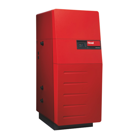
Hoval UltraGas 15 Technical Information Installation Instructions
Condensing gas heating boilers for natural gas and liquid gas for modulating operation
Hide thumbs
Also See for UltraGas 15:
- Installation instructions manual (52 pages) ,
- Technical information installation instructions (46 pages)
Table of Contents
Advertisement
Quick Links
Technical information
Installation instructions
UltraGas
(15-50)
®
Condensing gas heating boilers
for natural gas and liquid gas
for modulating operation
Hoval products may only be installed and commissioned
by appropriately qualified experts. These instructions
are intended exclusively for the specialist. Electrical
in stal lations may only be carried out by a qualified
electrician.
Subject to modifi cations
|
4 217 213 / 01 - 05/18
These instructions apply to the following types:
Rated output levels at 40/30 ºC
and for natural gas
45-UltraGas
(15)
®
45-UltraGas
(20)
®
45-UltraGas
(27)
®
45-UltraGas
(35)
®
45-UltraGas
(50)
®
The floor-standing gas condensing boilers UltraGas
(15-50) acc. to EN 15502-1/15502-2-1 are suitable and
licensed for use as heat generators for hot water heat-
ing systems with a permissible flow temperature of up
to 85 °C
. They are designed for continuously control-
1)
led reduced operation in heating systems.
See technical data
1)
3.1 - 15.5 kW
4.0 - 20.2 kW
5.0 - 27.2 kW
5.8 - 35.7 kW
8.3 - 50.1 kW
®
EN
Advertisement
Table of Contents

Related Manuals for Hoval UltraGas 15


Summary of Contents for Hoval UltraGas 15
- Page 1 ® 45-UltraGas (50) 8.3 - 50.1 kW ® Hoval products may only be installed and commissioned The floor-standing gas condensing boilers UltraGas ® by appropriately qualified experts. These instructions (15-50) acc. to EN 15502-1/15502-2-1 are suitable and are intended exclusively for the specialist. Electrical...
-
Page 2: Table Of Contents
TABLE OF CONTENTS Important notes General safety instructions ..............................4 Explanation of the symbols ..............................4 1.2.1 Warnings ..................................4 1.2.2 Warning symbols................................4 1.2.3 Information ..................................5 Acceptance of delivery ................................5 Scope of guarantee ................................5 Instruction manuals ................................5 Regulations, official permits ...............................6 1.6.1 Germany § ..................................6 1.6.2 Austria §... - Page 3 TABLE OF CONTENTS Commissioning Safety information ................................31 Filling with water ................................31 Water quality ..................................32 5.3.1 Heating water..................................32 Bleeding the air from the gas line .............................33 Switching on the system ..............................33 Gas inlet pressure ................................33 Functional check of combustion cylinder pressure monitoring ..................33 5.7.1 Check pressure in the combustion cylinder (safety check during commissioning) ............34 Setting the gas quantity, measuring the CO...
-
Page 4: Important Notes
IMPORTANT INFORMATION Important notes Explanation of the symbols General safety instructions 1.2.1 Warnings The system shall not be put into operation DANGER until all relevant standards and safety regula- tions are met..indicates a situation of immediate danger which will lead to serious or fatal injuries if not avoided. -
Page 5: Information
§ Refers to standards and directives. A summary of all the instruction manuals relevant to this system can be found in the Hoval System User Guide! In exceptional cases the instructions are kept with the re- spective components! Additional sources of information: •... -
Page 6: Regulations, Official Permits
IMPORTANT INFORMATION Regulations, official permits 1.6.3 Switzerland § When installing and operating the system, the standards • SN EN 12831 Heating systems in buildings - Methods and regulations spec i fied in point 1.6.1 to 1.6.3 must be for calculating the design heat load complied with at all times. -
Page 7: Assembly
ASSEMBLY Assembly Set-up, levelling The boiler is fixed to wooden transport chocks. For trans- port up and down stairs, it is wise to leave these timbers in place under the boiler. A special foundation plate for the boiler is not an essen- tial, but it is recommended. -
Page 8: Technical Data Description Of The Boiler
® con densing gas boiler comprising the Ultraclean burner sys tem, a gas fired premix burner with combustion air fan. The Hoval UltraGas has a vertically disposed com- ® bustion chamber of stainless steel as a primary heating sur face and a secondary heating surface of a corrosion re si stant aluminium alloy. -
Page 9: Technical Data Ultragas ® (15-50)
TECHNICAL INFORMATION Technical data UltraGas (15-50) ® Type (15) (20) (27) (35) (50) • Nominal heat output at 80/60 °C, natural gas 3.0-14.3 3.8-18.7 4.5-25.0 (50) 5.2-32.8 • Nominal heat output at 40/30 °C, natural gas 3.3-15.5 4.3-20.3 5.0-27.2 5.8-35.7 5.8-35.7 •... -
Page 10: Dimensions
TECHNICAL INFORMATION Dimensions (Dimensions in mm) Type UltraGas (15-27) (35,50) ® Heating flow / safety flow R 1" R 1¼" Low temperature-return R 1" R 1¼" Fig. 03 High temperature-return R 1" R 1¼" Gas connection Rp ¾" Rp ¾" Flue gas outlet DN80 DN80... -
Page 11: Space Requirements
TECHNICAL INFORMATION Space requirements (Dimensions in mm) Fig. 04 Boiler door incl. burner swings upward and to the left or outward. A = minimum 150 mm * - Burner service position front - boiler cleaning from the right A = optimum 300 mm * - Burner service position left - boiler cleaning from the front - Boiler can be placed with the right side directly... -
Page 12: Boiler-Flow Resistance
TECHNICAL INFORMATION Boiler-Flow resistance Brief description of the automatic firing device UltraGas (15-27) ® The automatic firing device BIC960 of the UltraGas only ® operates in conjunction with the heating controller Top- Tronic E/UG. For this reason, the automatic firing device ®... -
Page 13: Installation
INSTALLATION Installation 4.2.2 Room sealed installation Configuration based on a concentric flue system: Safety information - The suction air is supplied through a double-wall flue system. CAUTION - Ensure the boiler room is sufficiently ventilated. Sharp edges pose a cutting hazard. Handle the cladding parts with care Configuration using a separating piece (optional): and avoid contact with sharp edges. -
Page 14: Flue Gas Connection And Flue
The flue gas system must meet the following requirements: Your Hoval dealer can supply an approved flue gas sys- • Gastight tem suitable for your UltraGas (15,20,27,35,50). ®... -
Page 15: Project Planning Instructions, Flue Gas Systems
(bearing rail or pipe clip). Flue gas temperature The Hoval flue duct systems E80 PP, E100 PP, E80 Flex PP, E100 Flex PP, C80/125 PP, C100/150 PP and E130 PP are long-term temperature resistant to 120 °C. -
Page 16: Design Examples For Room Air Dependent Operation
Use the suitable flue gas system from Hoval or a flue gas stallation. For the remaining formpieces which have to be system certified in accordance with DIN EN 14471. Stain-... -
Page 17: Design Examples For Room Air Independent Operation
ASSEMBLY 4.3.3 Design examples for Assembly kit UG K C80/125 PP room air independent operation UG K C80/125 Flex PP UltraGas (35) ® Combustion air UltraGas (27) ® UltraGas (20) ® If necessary, insert an inspection T-piece UltraGas (15) ® UltraGas (50) ®... - Page 18 ASSEMBLY Ambient air independent operation Example UG K-LAS C80/125 PP Connection assembly kit LAS to UltraGas ® Approval Boiler connection piece E80 ->C80/125 PP, L = 200 mm VKF-No. Z 14603 CE 0432BPR220556 Inspection T-piece C80/125 PP with measure opening Wall plate to wall duct C80/125;...
- Page 19 ASSEMBLY Assembly kit UG AW C80/125 PP Combustion UltraGas (35) ® UltraGas (27) ® UltraGas (20) ® If necessary, insert an inspection T-piece UltraGas (15) ® Maximum horizontal length connecting pipe (m) Assembly kit UG AW C100/150 PP UltraGas UltraGas (50) ®...
-
Page 20: Condensate Drain
INSTALLATION Condensate drain Possibility 3 - see chapter 4.4.4 • Siphon and condensate delivery pump The boiler condensate drain must be made • Without neutralisation, condensate discharge into high- of corrosion-resistant material. The following er drain line. materials are suitable for the condensate dis- charge: •... -
Page 21: Fitting The Condensate Drain (Standard Design With Siphon)
INSTALLATION 4.4.2 Fitting the condensate drain CAUTION (standard design with siphon) Before commissioning, the siphon must be 1. Remove front cover (1a, Fig. 09). Release lateral filled with water in order to prevent flue gas locking bolt (1, Fig. 09) (approx. ¼ turn to the left). Lift leakage. -
Page 22: Fitting The Neutralisation Box
INSTALLATION 4.4.3 Fitting the neutralisation box 5. Fit rear cover (9, Fig. 12) of the neutralisation box. 6. Fit jubilee clip (10, Fig. 12) approx. 20mm from the (if fitted) upper end of the hose and tighten slightly. The hose 1. -
Page 23: Fitting The Condensate Delivery Pump
INSTALLATION 4.4.4 Fitting the condensate delivery pump 8. The hose of the siphon (11, Fig. 14) can be easily pushed onto the drain connection of the condensate 1. Install the condensate delivery pump (14, Fig. 17) as drip tray by lifting the neutralisation box (10a, Fig. 12). shown in the drawing. -
Page 24: Fitting The Neutralisation Box And The Condensate Delivery Pump
INSTALLATION 4.4.5 Fitting the neutralisation box and 4. Remove front cover (1a, Fig. 20). Release lateral locking bolt (1, Fig. 20) (approx. ¼ turn to the left). Lift the condensate delivery pump the front cover straight upwards and remove towards 1. -
Page 25: Gas Connection
INSTALLATION 8. Slide the neutralisation box (11, Fig. 22) into the boiler 11. Fill the neutralisation box with water. until the hose of the siphon (10a, Fig. 21) is directly 12. Fit the front cover (13, Fig. 25) of the neutralisation. beneath the drain connection. -
Page 26: Hydraulic Connection
Optional Regarding suitable hydraulic connections, TopTronic E room control module ® please observe the notes in the planning doc- TTE-GW TopTronic Gateway ® u mentation of the relevant Hoval sales com- pany! 4 217 213 / 01... -
Page 27: Electrical Connection
INSTALLATION Electrical connection Important! A main switch must be installed on-site in the supply line A qualified technician must install the electri- which performs an all-poles cut-out and has a clearance cal supply to the equipment. of at least 3 mm between the open contacts. The connection diagram is located in the elec- trical box of the heat generator;... -
Page 28: Safety Measures For Emc According Assembly
INSTALLATION 4.7.1 Safety measures for EMC according assembly • Measures must be taken in the building and on electri- cal equipment to protect the units against overvoltage caused by lightning strikes. • Cables carrying mains voltage must be routed sepa- •... - Page 29 INSTALLATION In the case of star-shaped data bus networks, double Disadvantages of an inter-building installation earthing is not permitted. The earthing must be carried - Increased susceptibility to interference, communica- out on one side at the star point. tion problems - Voltage surge damage To ensure correct electrical installation, unit connec- Abschirmung...
-
Page 30: Recommended Cable Cross Sections And Permissible Maximum Length Of Cable
INSTALLATION 4.7.2 Recommended cable cross sections and permissible maximum length of cable Line type Cross-section Length Power supply of the min. 1.5 mm unlimited m heat generator (230 V) with 13 A fuse Cables carrying mains min. 1.0 mm unlimited m supply voltages from actuators Cables carrying low... -
Page 31: Commissioning
• Maintenance and cleaning work may only sion agents. be performed by trained personnel or by • When transferring to operation without anti- the Hoval Customer Service. freeze or anti-corrosion agents, the system is to be thoroughly flushed through several times before refilling with water. -
Page 32: Water Quality
In particular, attention must be paid to the following stipu- lations: Filling and replacement water • Hoval boilers and calorifi ers are designed for heating • For a plant using Hoval boilers untreated drinking water plants without signifi cant oxygen intake (plant type I ac- is generally best suited as heating medium, i.e. -
Page 33: Bleeding The Air From The Gas Line
• Ensure that combustion air is supplied and flue gas is discharged. WARNING The heat generator is live when it has been In order to ensure safety, the Hoval UltraGas is equipped ® connected to the mains. with a pressure monitoring device on the combustion cyl- inder. -
Page 34: Check Pressure In The Combustion Cylinder (Safety Check During Commissioning)
B17 and B18 must be adjusted to the conditions on site. WARNING The settings must only be changed by a spe- cialist trained by Hoval or by Hoval customer service. 1. Slightly loosen top screw on pressure switch B17 (connection point for the measurement). -
Page 35: Setting The Gas Quantity, Measuring The Co ) And Nox/Co Content In The Flue Gas (Flue Gas Measurement)
The settings on the gas/air compound reg- ulation must only be made by a specialist 1. Start the «Emission» menu on the control module. trained by Hoval or by Hoval customer ser- - The control automatically switches to normal opera- vice. -
Page 36: Changing To A Different Type Of Gas
- AMP connector at position 1 and 3. The changeover is only allowed to be carried 2. Stick the yellow «Change of set gas type: liquid gas» out by a recognised specialist or Hoval cus- stickers to the following places: tomer service. -
Page 37: Record - Activation Of Screed Function
COMMISSIONING 5.11 Record - Activation of screed function Description of function The control module of the TopTronic E contains a functional sequence used for drying out screed fl oors. To start the ® screed drying, it is necessary for the individual functions to be set accordingly. Flow temperature Heating-up phase Inertia phase... - Page 38 COMMISSIONING Function display Icon Function Screed drying active Various settings can be made as well. Prioritisation of the screed func- tion means the settings are only ac- tive at the end of the function. Information remaining run time Request of the active function phase, the ACT temperature as well as the remaining run time.
-
Page 39: Maintenance
MAINTENANCE Maintenance Water refilling The European Standard EN 14868 and the NOTICE § Directive VDI 2035 must be observed (see Missing or faulty cleaning and maintenance point 5.3). may cause damage to the installation. The heating installation must be surveyed and cleaned once a year. -
Page 40: Information For Combustion Controller/Chimney Sweep Regarding Emission Monitor Key
MAINTENANCE Information for combustion controller/ chimney sweep regarding emission monitor key This chapter is exclusively intended to describe the function of emissions and manual operation settings for the fi ring monitoring technician / chimney sweep. All operating elements are described in the operating instructions. CAUTION Danger of scalding with hot water, since the hot water temperature can exceed the target setpoint temperature. -
Page 41: Cleaning
The Hoval gas heating boiler should be cleaned and maintained once every year. If the Hoval gas heating boiler was in operation during the building phase, it will be necessary to carry out a check for cleanliness. If the boiler is dirty, clean it. -
Page 42: Cleaning The Exterior Of The Combustion Chamber And Burner Cylinder
MAINTENANCE 6.6.2 Cleaning the exterior of the combustion Cleaning: 1. Spray the combustion chamber and aluFer tubes chamber and burner cylinder ® (10, Fig. 36). The best results are obtained with a spray gun with WARNING a suitable wide jet nozzle (fan or conical jet). We rec- Chemical burn hazard through cleaning ommend, e.g.: Desoxin agents. -
Page 43: Leakage Testing
MAINTENANCE 6.6.3 Leakage testing Ignition electrode Ignition/ionisation electrode After cleaning or at least every five years, the seal be- tween the combustion chamber and the condensate drip tray must be checked for leakage. This can be done by filling the boiler with water. Fig. -
Page 44: Clean Siphon Or Neutralisation Box
MAINTENANCE Clean siphon or neutralisation box Design with neutralisation box (if fitted) 1. Set the main system switch to “0” 1. Set the main system switch to “0” 2. Remove the front panel (1, Fig. 42) 2. Remove the front panel (1, Fig. 41) 3. -
Page 45: Maintenance Of The Neutralisation Equipment (If Available)
(check the ph-value if appropriate with litmus paper test). Neutralisation granulate for refi lling can be ordered from Hoval under the following item no.: • 1 pack (3 kg) neutralisation granules Part no. 2028 906 One fi lling requires a pack of 3 kg... -
Page 46: Parameter List - Automatic Firing Device Bic 960
Parameter list - automatic firing device BIC 960 WARNING Changes to the BIC may only be made by authorised Hoval customer service technicians. The following table is intended solely to provide information for the Hoval customer service technician! Automatic firing device UltraGas (15-50) ®... - Page 47 PARAMETER LIST - AUTOMATIC FIRING DEVICE BIC 960 Parameter Description 2FJ 32799 Upward ramp of the fan during venting /s OEM –1 32 2FK 32800 Downward ramp of the fan during venting /s OEM –1 2FL 32801 Upward ramp of the fan during operation /s OEM –1 34 2FM 32802 Downward ramp of the fan during operation...
- Page 48 4 217 213 / 01...
- Page 49 4 217 213 / 01...
- Page 50 COPY FOR PLANT USER Confirmation The user (owner) of the system herewith confi rms that • he has received adequate instruction in the operating and maintenance of the installation, • received and taken note of the operating and maintenance instructions and, where applicable other documents con- cerning the heat generator and any further components.
Need help?
Do you have a question about the UltraGas 15 and is the answer not in the manual?
Questions and answers