Hoval BioLyt 50 Technical Information Installation Instructions
Wood pellet boiler
Hide thumbs
Also See for BioLyt 50:
- Operating instructions manual (66 pages) ,
- Operating instructions manual (24 pages) ,
- Technical data manual (18 pages)
Table of Contents
Advertisement
Quick Links
Technical information
Installation instructions
BioLyt (50-160)
Wood pellet boiler
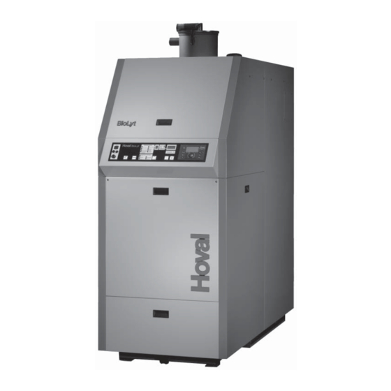
Figure: BioLyt (100-160)
Hoval products may only be installed and com-
missioned
by
appropriately
These instructions are intended exclusively for the spe-
cialist. Electrical installations may only be carried out
by a qualified electrician.
Subject to modifi cations
qualified
experts.
|
4 214 852 / 01 - 06/19
These instructions are applicable to the fol-
lowing types:
42-BioLyt (50)
42-BioLyt (70)
42-BioLyt (75)
42-BioLyt (100)
42-BioLyt (130)
42-BioLyt (150)
42-BioLyt (160)
49 kW
69 kW
73 kW
99 kW
130 kW
149 kW
156 kW
EN
Advertisement
Table of Contents

Related Manuals for Hoval BioLyt 50


Summary of Contents for Hoval BioLyt 50
- Page 1 130 kW 42-BioLyt (150) 149 kW 42-BioLyt (160) 156 kW Figure: BioLyt (100-160) Hoval products may only be installed and com- missioned appropriately qualified experts. These instructions are intended exclusively for the spe- cialist. Electrical installations may only be carried out by a qualified electrician.
-
Page 2: Table Of Contents
Europe § ...................................6 General assembly Characteristics of the boiler room ............................8 Installation and set-up .................................8 List of the screw packets (BioLyt 50-160) ..........................9 Assembly BioLyt (50-75) Changing the door attachment side BioLyt (50-75)......................10 Burner BioLyt (50-75) ................................10 Mounting the ash rotor BioLyt (50-75) ..........................11 Water-side and flue-gas side connection BioLyt (50-75) .................... - Page 3 6.1.6 Hydraulic integration ...............................43 Flue connection and dimensioning ..........................44 6.2.1 General information ................................44 6.2.2 Connecting 2 Hoval BioLyt (50-160) to a common chimney .....................44 Electrical connection .................................45 6.3.1 General information ................................45 6.3.2 Terminal plate with automatic firing device ........................46 Commissioning Water quality ..................................47...
-
Page 4: Important Notes Safety Instructions
IMpORTAnT nOTES Important notes 1.2.2 Warning symbols The following warning signs are combined for the war- Safety instructions ning notes with signal words CAUTION, WARNING and The system may only be placed in operation DANGER. if all the relevant standards and safety regula- General warning of a danger zone. -
Page 5: Manuals
Standards and directives All instructions relevant to your system can be found in 1.7.1 Germany § the Hoval system manual - please keep all manuals! EnEV Energy conservation ordinance in the current version. In exceptional cases, the instructions can be found with 1.BimSchV... -
Page 6: Austria
IMpORTAnT nOTES 1.7.3 Austria § 1.7.5 Europe § ÖNORM H5151-1 Design of hot water central heating EN 303-5 Boilers for solid fuels with a heat out- systems with or without water heating. put of up to 300 kW. ÖNORM H5170 Heating systems - Requirements with EN 1443 Waste gas systems, general require-... - Page 7 NOTES 4 214 852 / 01...
-
Page 8: General Assembly Characteristics Of The Boiler Room
GEnERAL ASSEMBLy General assembly Characteristics of the boiler room The architectural and ventilation requirements for boiler rooms are defined in the building regulations applicable to the relevant installation site. Ensure an adequate supply of fresh air to the boiler room to make sure that there is an unobstructed flow of the combustion air required for the operation of all combus- tion devices in the boiler room and so that there is no... -
Page 9: List Of The Screw Packets (Biolyt 50-160)
GEnERAL ASSEMBLy 4 214 852 / 01... -
Page 10: Assembly Biolyt
ASSEMBLy BIOLyT (50-75) Assembly BioLyt (50-75) Burner BioLyt (50-75) The gap between the burner tube and the combustion Changing the door attachment side chamber insulation is to be filled with the stuffing wool (1) BioLyt (50-75) provided (Fig. 03). BioLyt (50) 1. -
Page 11: Mounting The Ash Rotor Biolyt (50-75)
(screws provided with the rotor). • The correct functioning of the rotor must be checked when the boiler is commissioned by Hoval Service. Fig. 08 4 214 852 / 01... -
Page 12: Fitting The Thermal Insulation Biolyt (50-75)
ASSEMBLy BIOLyT (50-75) 4 214 852 / 01... -
Page 13: Fitting The Burner Biolyt (50-75)
ASSEMBLy BIOLyT (50-75) 4 214 852 / 01... -
Page 14: Fitting The Pellet Hopper Biolyt (50-75)
ASSEMBLy BIOLyT (50-75) 4 214 852 / 01... - Page 15 ASSEMBLy BIOLyT (50-75) 4 214 852 / 01...
-
Page 16: Fitting The Probes, Sensors And Cables Biolyt (50-75)
ASSEMBLy BIOLyT (50-75) 4 214 852 / 01... - Page 17 ASSEMBLy BIOLyT (50-75) 4 214 852 / 01...
-
Page 18: Fitting The Casing Biolyt (50-75)
ASSEMBLy BIOLyT (50-75) 4 214 852 / 01... - Page 19 ASSEMBLy BIOLyT (50-75) 4 214 852 / 01...
-
Page 20: Fitting The Ash Box And Miscellaneous Biolyt (50-75)
ASSEMBLy BIOLyT (50-75) 3.10 Fitting the ash box and miscellaneous BioLyt (50-75) 36. Slide the ash box (50) into the screw pipe (do not forget the O-ring 50a, Fig. 21); the height of the rollers can be adjusted by means of the nuts provided on the sides. The ash box (50) must be aligned using the adjustable roller supports, as otherwise the connection to the boiler will not be airtight. - Page 21 NOTES 4 214 852 / 01...
-
Page 22: Assembly Biolyt
ASSEMBLy BIOLyT (100-160) Assembly BioLyt (100-160) Water-side and flue-gas side connecti- on BioLyt (100-160) Changing the door attachment side BioLyt (100-160) • The boiler can be connected up before fitting the casing • A return temperature control system is required (see 1. -
Page 23: Fitting The Thermal Insulation Biolyt (100-160)
ASSEMBLy BIOLyT (100-160) Fitting the thermal insulation BioLyt (100-160) Attachment set D 6. Attach the insulation mat (1, 1a, 1b, 1c) on the pins 9. Place insulation mat (4) around the top of the water provided on the front of the boiler and secure with jacket (black side outwards) and secure with tension iso-clips (Fig. -
Page 24: Fitting The Burner Biolyt (100-160)
ASSEMBLy BIOLyT (100-160) 4 214 852 / 01... - Page 25 ASSEMBLy BIOLyT (100-160) 4 214 852 / 01...
-
Page 26: Fitting The Pellet Hopper Biolyt (100-160)
ASSEMBLy BIOLyT (100-160) 4 214 852 / 01... - Page 27 ASSEMBLy BIOLyT (100-160) 4 214 852 / 01...
-
Page 28: Fitting The Probes, Sensors And Cables Biolyt (100-160)
ASSEMBLy BIOLyT (100-160) 4 214 852 / 01... - Page 29 ASSEMBLy BIOLyT (100-160) 4 214 852 / 01...
-
Page 30: Fitting The Casing Biolyt (100-160)
ASSEMBLy BIOLyT (100-160) 4 214 852 / 01... - Page 31 ASSEMBLy BIOLyT (100-160) 4 214 852 / 01...
-
Page 32: Fitting The Ash Box And Miscellaneous Biolyt (100-160)
ASSEMBLy BIOLyT (100-160) Fitting the ash box and miscellaneous BioLyt (100-160) 40. Slide the ash box (50) into both screw pipes (do not forget the O-rings (50a), Fig. 38); the height of the rollers can be adjusted by means of the nuts provided. The ash box (50) must be aligned using the adjustable roller supports (50b), as otherwise the connection to the boiler will not be airtight. -
Page 33: Safety Precaution For Installation In Line With Emc Requirements
ASSEMBLy BIOLyT (100-160) 4.8.1 Safety precaution for installation in line • Measures must be taken in the building and on electri- cal equipment to protect the units against overvoltage with EMC requirements caused by lightning strikes. • The mains connection for the heating system must be •... - Page 34 ASSEMBLy BIOLyT (100-160) • Measures must be taken in the building and on electri- cal equipment to protect the units against overvoltage caused by lightning strikes. • The mains connection for the heating system must be • Cables carrying mains voltage must be routed sepa- rately from sensor or data bus cables.
-
Page 35: Technical Information
TEChnICAL InFORMATIOn Technical information Brief technical description The combustion system achieves an excellent pellet The BioLyt has been designed for the low-emission com- burnout rate. Thanks to the large, mostly refractory lined bustion of wood pellets in accordance with ÖNORM M combustion chamber, it is possible to attain a long dwell 7135 and DIN 51731, HP5 (or DINplus) and EN 14961-2, time of the hot gases, as well as sufficiently high combus-... -
Page 36: Technical Data
The installation of a damper is generally recommended. Min. 16 A protection because of operating current. For configuration of the boiler in accordance with the off-periods of the suction turbine, filling times (BioLyt 50,70) and the burner cleaning times of the boiler. -
Page 37: Dimensions Biolyt (50-75)
TEChnICAL InFORMATIOn Dimensions BioLyt (50-75) (Dimensions in mm) Boiler flow connection R 1¼″ Installation flow connection R 1¼″ Boiler return connection R 1¼″ Installation return connection R 1¼″ Safety heat exchanger 2 x R ½″ Draining R ¾″ Flue gas connection external Ø... -
Page 38: Dimensions Biolyt (100)
TEChnICAL InFORMATIOn Dimensions BioLyt (100) (Dimensions in mm) Boiler flow connection DN 50 Installation return connection DN 50 Safety heat exchanger 2 x R ½″ Draining R 1″ Flue gas connection external Ø 180 mm Electric control optionally left or right Suction ventilator Connection conveyor hose Ø... -
Page 39: Dimensions Biolyt (130-160)
TEChnICAL InFORMATIOn Dimensions BioLyt (130-160) (Dimensions in mm) Boiler - flow connection DN 50 System - return connection DN 50 Safety heat exchanger 2 x R ½″ Drain R 1″ Flue gas outlet External Ø 180 mm optionally on the left Electrical controller or right hand side Induced-draught fan... -
Page 40: Space Requirement
TEChnICAL InFORMATIOn Space requirement (Dimensions in mm) Space requirements BioLyt (50-75) This area must remain free for maintenance work BioLyt Type H (50) 2160 1660 740 (70) 2250 1685 800 Minimum distance to wall on the control side 700 mm, on the opposite side 150 mm. - Page 41 TEChnICAL InFORMATIOn Overall unit dimensions BioLyt (50-160) BioLyt type (50) 1790 1650 1430 1255 (70-75) 1880 1740 1430 1255 (100) 1940 1775 1430 1290 (130, 160) 1940 1775 1880 1810 Space requirement automatic ash removal (Dimensions in mm: Fig. BioLyt (130,160), also applies to BioLyt (100)) The automatic ash removal can be fitted on both sides, i.e.
-
Page 42: Installation
InSTALLATIOn Installation 6.1.5 Additional installation information Automatic filling of the pellet container Water connections When deciding on the placement of the BioLyt boiler, you 6.1.1 General provisions must take into consideration the space requirements for The BioLyt wood pellet boiler (50-160) is designed and the automatic conveying of pellets from the correspon- approved for use as a heat generator for domestic hot ding storage room. -
Page 43: Hydraulic Integration
InSTALLATIOn 6.1.6 hydraulic integration BioLyt (50-160) Pellet boiler with - energy buffer storage tank (> 20 l/kW) - calorifier - 1-... mixer circuit(s) Hydraulic schematic BCDE010 TTE-GW TTE-WEZ TTE-PS TTE-FE B1.1 B1.2 Option/opzione 2. Puffer 2. Buffer 2. Accumulatore BioLyt ³ 50 PF-A 2. -
Page 44: Flue Connection And Dimensioning
Connect the flue gas pipe to the flue gas system elastically. A moisture-resistant flue is required for the correct ope- ration of the Hoval BioLyt. Watertight and acid-proof flue gas systems should be used in new installations. ref. c) -
Page 45: Electrical Connection
InSTALLATIOn Electrical connection 6.3.1 General information Important! A qualified technician must install the electri- A main switch must be installed on site in the supply line cal supply to the equipment. which performs an all-poles cut-out and has a clearance The connection diagram is located in the elec- of at least 3 mm between the open contacts. -
Page 46: Terminal Plate With Automatic Firing Device
InSTALLATIOn 6.3.2 Terminal plate with automatic firing device WARNING When routing the cables, ensure that the cables do not touch any hot or sharp-edged components and that they are not damaged in any way. Fig. 40 NOTICE The cables that lead from the burner mecha- nism to the clamping plate must be bundled so that the burner can be swivelled open wi- thout difficulty. -
Page 47: Commissioning
In particular, attention must be paid to the following stipu- Filling and replacement water lations: • For a plant using Hoval boilers untreated drinking water • Hoval boilers and calorifi ers are designed for heating is generally best suited as heating medium, i.e. as fi ll- plants without signifi cant oxygen intake (plant type I ac- ing and replacement water. -
Page 48: Filling Up The Heating System, The Calorifier (If Fitted) And Hot Water Buffer Storage Tank
9. Combustion air supply available? Important note: The BioLyt unit may only be 10. Are all motors and fans connected correctly (relay put into operation by Hoval customer service. test)? Otherwise, all warranty claims will be void. 11. Are all sensors and probes connected correctly? -
Page 49: Maintenance
MAInTEnAnCE Maintenance Burner tube cleaning procedure: Cleaning the boiler NOTICE See operating instructions for cleaning intervals and clean- ing procedures. Ensure that there are no glowing embers. Otherwise, your vacuum cleaner could be destroyed! NOTICE Boiler must not be wet- cleaned. -
Page 50: Safety Temperature Limiter - Reset
MAInTEnAnCE Safety temperature limiter - Reset If the boiler temperature rises too high (>100 °C), the system is switched off by the safety temperature limiter (STL) by means of a mechanical lockout. The malfunction must first be unlocked on the safety temperature limiter, then on the control panel (with reset button). 1. - Page 51 4 214 852 / 01...
- Page 52 COPY FOR PLANT USER Confirmation The user (owner) of the system herewith confi rms that • he has received adequate instruction in the operating and maintenance of the installation, • received and taken note of the operating and maintenance instructions and, where applicable other documents con- cerning the heat generator and any further components.
Need help?
Do you have a question about the BioLyt 50 and is the answer not in the manual?
Questions and answers