Hoval BioLyt 50 Operating Instructions Manual
Wood pellet boiler
Hide thumbs
Also See for BioLyt 50:
- Operating instructions manual (24 pages) ,
- Technical data manual (18 pages) ,
- Technical information installation instructions (52 pages)
Table of Contents
Advertisement
Quick Links
Download this manual
See also:
Technical Data Manual
Operating Instructions
BioLyt (50,70,75)
BioLyt (100,110,130,150,160)
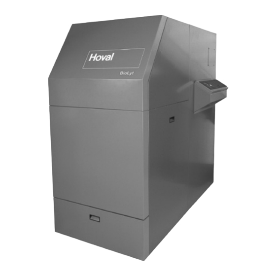
Wood pellet boiler
Subject to modifi cations
Figure: BioLyt (50-75)
Figure: BioLyt (100-160)
|
4 212 945 / 00 - 04/14
United Kingdom
Hoval Ltd.
Northgate
Newark
Nottinghamshire NG24 1JN
Phone
+44 1636 67 27 11
Fax
+44 1636 67 35 32
Export
Hoval Aktiengesellschaft
Austrasse 70
9490 Vaduz
Principality of Liechtenstein
Phone
+423 399 24 00
Fax
+423 399 24 11
EN
Advertisement
Table of Contents

Related Manuals for Hoval BioLyt 50


Summary of Contents for Hoval BioLyt 50
- Page 1 Operating Instructions BioLyt (50,70,75) BioLyt (100,110,130,150,160) Wood pellet boiler United Kingdom Hoval Ltd. Northgate Newark Nottinghamshire NG24 1JN Phone +44 1636 67 27 11 +44 1636 67 35 32 Export Hoval Aktiengesellschaft Austrasse 70 9490 Vaduz Principality of Liechtenstein Phone...
-
Page 2: Table Of Contents
Information about your heating system ................4 Fuel quality / pellet delivery ........................4 1.1.1 Fuel quality ..............................4 1.1.2 Pellet delivery ............................4 Important addresses and telephone numbers ..................4 BioLyt (50-160) wood pellet boiler ......................4 Important information ......................5 Key to symbols used .......................... - Page 3 4.11 System information ..........................40 4.11.1 Information key for system temperatures and heating circuit information ..........40 4.11.2 Information on the boiler status ....................... 41 4.11.3 Displaying and resetting the consumption meters and cleaning messages ..........43 4.11.4 Changing off-periods for the extraction system ..................46 4.11.5 Special symbols ............................
-
Page 4: Information About Your Heating System
Dear heating system owner, Heating engineer _________________________ With the purchase of this Hoval BioLyt (50-160) wood pellet boiler, you have made an excellent cho- ________________________________________ ice. It offers you all the advantages of a modern and ________________________________________ efficient heating system. -
Page 5: Important Information
Important information • Parents must keep their children Key to symbols used away from the boiler room; the Please pay particular attention to the following sym- heating system is not a toy! bols used in this operating manual. • Do not burn unsuitable fuel (see Chapter 1.1);... -
Page 6: Cautionary Notes
(as in the case of under- Periodic cleaning and inspection by the heating en- ground tanks), the person entering the tank must gineer or Hoval customer service will not only extend be additionally secured. the service life of the pellet boiler, but also increase its operating safety and ensure that a high combus- •... -
Page 7: Functional Principle Of The Heating System
Functional principle of the heating system It is important that the perfectly coordinated individual components function properly to ensure that your home stays warm in winter. COMPONENTS FUNCTION: Burns the pellets safely and in an environmentally fri- Wood pellet endly manner.. boiler Extracts the heat from the combustion gases and transfers it to the heating water. - Page 8 Adjusts the heating flow temperature to the radiator Mixing valve to maintain the desired room temperature whatever the outside temperature. This is achieved by mixing in colder return heating water. Displays the water pressure in the heating system. Pressure gauge Ensures that the heating pipes contain only heating Air vent water and no air.
-
Page 9: What Happens Inside The Biolyt
What happens inside the BioLyt? The Hoval BioLyt has been designed for the low- The horizontal combustion results in a flame simi- emission combustion of wood pellets in accordance lar to that of an oil or gas burner. The combustion with ÖNORM M 7135 and DIN 51731, HP5 (or DIN-... -
Page 10: How Are The Pellets Extracted And Conveyed From The Storage Room
How are the pellets extracted and The extraction system can be disabled during two periods of time per day (e.g. to avoid unwelcome conveyed from the storage room? noise during the night). The factory settings are from The pellets are extracted from the storage room by 12.30 p.m. -
Page 11: Heating System Control
The correct settings for the heating system have to consider acquiring a “remote control” already been applied by Hoval, or the installer, du- from Hoval, which will allow you to ope- ring commissioning. Any changes to those settings... -
Page 12: Operating And Display Elements
Operating and display elements 4.4.1 Function of the operating elements The central PUSH & TURN button and the labelled keys are designed for easy and straightforward operation. PUSH & TURN button: Change and store values Function keys Function keys 4.4.2 Basic procedure for changing settings An example Select the desired function... -
Page 13: What To Do If
4.4.3 What to do if ... The following information can be used as a first level support in frequently occurring situations. Observation Remedy Set higher values for the room temperature with and the rotary button It is too cold (Chapter 4.4.1). Set lower values for the room temperature with and the rotary button It is too warm... -
Page 14: Control Elements On The Boiler Control Panel
4.4.4 Control elements on the boiler control panel A 2nd electronic heating regulator can be installed here (for 2nd residential unit) if required. Designation Function Switch off and block the boiler Blocking switch (e.g for cleaning). Daytime room temperature Set the daytime room temperature. Chap. - Page 15 Designation Function Operating mode Select the operating modes selection key . . . Turn off the heating system while you are on holiday Holiday (frost protection) Chap. 4.6.1 - 4.6.3 Absence Switch off the heating temporarily Chap. 4.6.1 - 4.6.3 ...
-
Page 16: Main Settings
Main settings These adjustments can also be carried out on a room station. 4.5.1 Changing the room temperature 4.5.1.1 Setting the desired room temperature, day Start - Basic display Mo 16 AUG. ' 04 14 / 00 / 62. 5 Tap the “Daytime room temperatu- re”... -
Page 17: Setting The Desired Reduced (Night-Time) Temperature
4.5.1.2 Setting the desired reduced (night-time) temperature Start - Basic display Mo 16 AUG. ' 04 14 / 00 / 62. 5 Tap the “Reduced room temperatu- re” key. If “MC1” is shown on the display, The night-time room temperature you need to select the heating cir- ROOM NIGHT setpoint flashes. -
Page 18: Operating Modes
Operating modes 4.6.1 Function of the operating modes Function Application Operating mode HOLIDAY - Heating system off while you are on holiday. You are going on holiday for e.g. 1 week and you - Room temperature set to minimum (10°C). know the date of your return. -
Page 19: Operating Modes For Holiday And Absence
4.6.2 Operating modes for holiday and absence? Depending on how long you will be away and what your requirements are with re- gard to comfort, there are different operating modes available for interrupting or re- ducing the heating. In any case, you will save a lot of energy and money if the rooms are not heated or heated less during your absence. -
Page 20: Changing The Operating Mode - For "Holiday Til," "Absent Til" And "Party Til
4.6.3 Changing the operating mode - for "HOLIDAY TIL," "ABSENT TIL" and "PARTY TIL" Procedure for activating the operating modes “HOLIDAY TIL”, “ABSENT TIL” or “PARTY TIL”. Tap the “Operating mode selection” . . . key. “OP. MODE” is displayed briefly. OP. -
Page 21: Changing The Operating Mode - For "Automatic," "Summer," "Heating," "Red. Heating" And "Standby
4.6.4 Changing the operating mode - for "AUTOMATIC," "SUMMER," "HEATING," "RED. HEA- TING" and "STANDBY" Procedure for activating the operating modes “AUTOMATIC”, “SUMMER” , “HEATING”, “RED. HE- ATING” and “STANDBY” Follow the steps 1 to 3 described in Chapter 4.6.3 “Changing the ope- rating mode”! "AUTOMATIC,"... -
Page 22: Switching Times (Heating Times)
Switching times (heating times) In this menu, the switching times programs can be set individually for the heating and DHW modes. The default heating times preset by the manufacturer are overwritten. However, you can restore the default times easily (see Chapter 4.10.5). It is possible to program up to 3 heating times per day. -
Page 23: Changing The Switching Times (Heating Times)
4.7.3 Changing the switching times (heating times) Start - Basic display Mo 16 AUG. ' 04 14: 0 0 62. 5 Press the “PUSH & TURN button” for at least 3 sec. “TIMEPROGRAMS” is shown flas- TIMEPROGRAMS hing on the display. Tap the “PUSH &... - Page 24 Change the flashing value by tur- The first day of the week is shown 0 2 4 6 8 10 12 14 16 18 20 22 24 ning the “PUSH & TURN button.” 06. 0 0-22. 0 0 flashing on the display. Acknowledge by tapping the MO-1- “PUSH &...
- Page 25 Tap the “PUSH & TURN button” to acknowledge the set end time. After confirmation of the end time, 0 2 4 6 8 10 12 14 16 18 20 22 24 06. 0 0-22. 0 0 the day of the week flashes again. MO-1- Turn the "Push &...
-
Page 26: Copying Switching Times
4.7.4 Copying switching times Follow the steps 1 to 8 described in Chapter 4.7.3 “Changing the switching times”! Select the “COPY”, “DAY” by turning the “PUSH & TURN button.” The settings flash on the display. COPY Tap the “PUSH & TURN button” to acknowledge the settings. - Page 27 Tap the “PUSH & TURN button” briefly to acknowledge the setting. Confirmation for correct copying of COPY day(s). The same value as in the preceding Target range for the next copy pro- COPY MO action is copied to the target range! cess is shown flashing on the dis- play.
-
Page 28: Heating Curve
Heating curve 4.8.1 Heating curve (heating characteristic curve) The heating curve describes the flow temperature of a heating system as a function of the outside temperature. The heating curve is preset by the installer *. Carry out temporary changes to the room temperature settings via the “Dayti- me room temperature”... -
Page 29: Changing The Heating Curve (Heating Characteristic Curve)
4.8.2 Changing the heating curve (heating characteristic curve) Mo 16 AUG. ' 04 Start - Basic display 14 / 00 / 62. 5 Tap the "Heating characteristics“ key. "Heating curve“ - display appears, HEAT. CURVE "HC“ flashes Select the desired heating circuit by turning the “PUSH &... -
Page 30: Hot Water
Turn the PUSH & TURN button to set further heating circuits... For example “MC” (flashing). “Heating curves” appears again on HEAT. CURVE the display. 1. 0 0 The start display is shown (basic Tap the “Operating mode selection” . . . display). -
Page 31: Manual Dhw Re-Charging
4.9.2 Manual DHW re-charging In the case of increased hot water demand, it is possible to conduct a temporary additional heat-up of the calorifier. The calorifier is then re-charged once according to the set daytime hot water temperature. Start - Basic display Mo 16 AUG. -
Page 32: Domestic Hot Water Economy Temperature (Reduced Temperature)
4.9.3 Domestic hot water economy temperature (reduced temperature) Start - Basic display Mo 16 AUG. ' 04 14 / 00 / 62. 5 Press the “PUSH & TURN button” for 3 seconds. “Switching times” is shown flashing TIMEPROGRAMS on the display. Change the DHW setting by tur- Setting range 0 - 240 min. - Page 33 The reduced night-time DHW tem- perature flashes. NIGHT 40. 0 Select the desired temperature va- lue by turning the “PUSH & TURN button.” Tap the “PUSH & TURN button” to acknowledge the setting. Tap the “Operating mode selection” The start display is shown (basic .
-
Page 34: Further Settings
4.10 Further settings 4.10.1 Setting the clock Follow the steps 1 to 3 described in Chapter 4.9.3 “Domestic hot water economy temperature”! Select “Time-date” by turning the “PUSH & TURN button.” “Time-date” is shown flashing on TIME - DATE the display. Tap the “PUSH &... -
Page 35: Setting The Date
4.10.2 Setting the date Continuation of ”Setting the clock” “Year” is shown flashing on the dis- YEAR (Chapter 4.10.1). play - acknowledge. 2004 Change the year setting by turning the “PUSH & TURN button” - ack- nowledge. Return to the starting page and save “Day...Month”... -
Page 36: Setting The Language
4.10.4 Setting the language You will be prompted for the desi- Follow the steps 1 to 3 described in red language when switching on Chapter 4.9.3 “Domestic hot water the control system for the first time. economy temperature”! Changing the language is also pos- sible during normal operation. -
Page 37: Reloading The Standard Switching Times Program - Deleting Your Own Time Program
4.10.5 Reloading the standard switching times program - Deleting your own time program This function allows you to reset all values preset at the factory! Follow the steps 1 to 3 described in Chapter 4.9.3 “Domestic hot water economy temperature”! Tap the “PUSH &... - Page 38 Tap the “PUSH & TURN button” to acknowledge the selected value. “Reset / HC” is displayed. RESET Press and hold the “PUSH & TURN button” for 3 sec. "Reset / OK" is displayed to ack- RESET nowledge. Tap the “Operating mode selection” key to acknowledge the new set- .
-
Page 39: Manual Operation
4.10.6 Manual operation The following information is intended for the heating technician only This function key is also used for emission measurement when it is only pressed briefly. - See installation instructions; combustion control All pumps are operating without restrictions. Available mixers are disconnec- ted and can be operated manually, if necessary, depending on the heat de- mand. -
Page 40: System Information
4.11 System information 4.11.1 Information key for system temperatures and heating circuit information Actual values Outside temperature OUTSIDE 7. 5 turn to left turn to right Heat generator Starts Heat generator tempe- rature STARTS HEAT GENER. 64. 5 Heat generator hours of operation Exhaust All temperature values shown represent... -
Page 41: Information On The Boiler Status
4.11.2 Information on the boiler status Viewing the current status of the heat generator. Start - Basic display Mo 16 AUG. ' 04 14 / 00 / 62. 5 Press the “PUSH & TURN button” for 3 seconds. “Switching times” is shown flashing TIMEPROGRAMS on the display. - Page 42 Tap the “PUSH & TURN button” to acknowledge the selected value. “STATUS” is shown flashing on the STATUS display. Turn the "PUSH & TURN button" to find the following values: Boiler status STATUS 0 Burner OFF, The burner is off and the boiler is Quiescent state in standby mode.
-
Page 43: Displaying And Resetting The Consumption Meters And Cleaning Messages
4.11.3 Displaying and resetting the consumption meters and cleaning messages Start - Basic display MO. 16 AUG. ' 04 14 / 00 / 62. 5 Press the “PUSH & TURN button” for 3 seconds. “TIMEPROGRAMS” is shown flas- TIMEPROGRAMS hing on the display. Select "FFA"... - Page 44 “COUNTER” is shown flashing on COUNTER the display. Tap the “PUSH & TURN button” to acknowledge the selected value. "CONSUMPTION 1" is shown flas- CONSUMPTION 1 hing on the display. Turn the "PUSH & TURN button" to find the following values: Viewing the consumption meters Pellet consumption for period: CONSUMPTION 1...
- Page 45 As an example, the procedure for resetting consumption meter 1 is described from step 12 onwards. "RESET CONS. 1" is shown flas- RESET CONS. . 1 hing on the display. Tap the “PUSH & TURN button” to acknowledge the selected value. “OFF”...
-
Page 46: Changing Off-Periods For The Extraction System
4.11.4 Changing off-periods for the extraction system Start - Basic display MO. 16 AUG. ' 04 14 / 00 / 62. 5 Press the “PUSH & TURN button” for 3 seconds. “TIMEPROGRAMS” is shown flas- TIMEPROGRAMS hing on the display. Select "FFA"... - Page 47 “FILLING” is shown flashing on the FILLING display. Tap the “PUSH & TURN button” to acknowledge the selected value. "PARAMETER 6" is shown flashing PARAMETER 6 on the display. 12: 3 0 Turn the "PUSH & TURN button" to find the following values: Changing the off-periods Time Begin filling off-period 1...
- Page 48 Set the desired time by turning the Repeat steps 11-15 if you “PUSH & TURN button.” wish to enter further off-pe- riods. Tap the “PUSH & TURN button” to acknowledge the selected value. The start display is shown Tap the "Information" key three (basic display).
-
Page 49: Special Symbols
4.11.5 Special symbols Ice crystal symbol: MO. 16 AUG. ' 04 System frost protection activated 14 / 00 / 62. 5 Sunshade symbol: MO. 16 AUG. ' 04 Summer disconnection active (heating switched off, DHW according to program). 14 / 00 / 62. -
Page 50: Optional Accessories
4.11.7 Optional accessories Room station RS-T The Room station RS-T offers additional operating convenience through decentralised monitoring and intervention options, since every heating circuit can be assigned with its own individual room station. Moreover, the central unit contains various control and regulating func- tions which can only be activated in conjunction with a room station. -
Page 51: Fault Repair
Fault repair Blocking switch and reset button The controller comprises a comprehensive alarm logic which displays the fault type by means of the corresponding error code, depending on the unit version. Press the Reset button under the hinged cover if the display shows “Error.” If this hap- Control Reset pens frequently, notify your Customer Ser-... -
Page 52: Overview Of Alarms, Heating Regulator Toptronic
Overview of alarms, heating regulator TopTronic ® FAULT REPORTING OVERVIEW TopTronic ® Status Designation Fault type Code Remark System External sensor Interruption 10-0 System External sensor Short-circuit 10-1 System Boiler sensor Interruption 11-0 System Boiler sensor Short-circuit 11-1 System Flow sensor 1 Interruption 12-0 MC1=off, YK1=no current... - Page 53 Regulator with address 10 is System Activity 70-8 missing System Activity Data bus error 70-9 No Hoval regulator System HP return sensor Return min. temp. below setpoint 85-4 System HP return sensor Return max. temp. exceeded 85-5 Heat source min. temp. below...
-
Page 54: Overview Of Alarms, Boiler Controller
(minimum combustion chamber temperature not re- ached after fire-bed build-up) E:29 Vacuum not OK Clean burner and boiler (see Chapter "Cleaning and maintenance“), if fault occurs repeatedly at short intervals, contact Hoval specialist E:31 Ball valve not closing/opening Contact Hoval specialist E:33 Ignition not successful Clean burner (see Chapter "Cleaning and maintenance“), if fault occurs... -
Page 55: Checklist In Case Of Faults
If you are not able to resolve Please use the above checklist when carrying out the checks in the fault, please contact the note! heating engineer or Hoval the case of malfunctions. Customer Service. 4 212 945 / 00 Fault repair... -
Page 56: Checking The Water Level
Checking the water level If the system pressure is too low (check pressure gauge), inform your installer or top it up with water. Refilling the heating system The heating system can normally be filled and top- ped up with mains water. In exceptional cases, the water quality may vary strongly and it might not al- ways be suitable for filling the heating system (highly corrosive or very hard water). -
Page 57: Maintenance Biolyt (50-75)
Maintenance BioLyt (50-75) Commissioning When commissioning the system, also observe the notes in the installation manual. 1. Checks: • Are the slide valves in the heating flow and return lines open? • Is the combustion air supply into the boiler room adequate? •... - Page 58 Cleaning every 2-6 months or every 6 tonnes of pellets (BioLyt 50) or every 8 tonnes of pellets (BioLyt 70,75) Only by service engineers 1. Switch off the burner: - Operate blocking switch Fig. 07 - Wait for burn-out to be completed 2.
- Page 59 (chimney sweep, installer or Hoval Customer Service). Fig. 09 Annual cleaning or every 18 tonnes of pellets (BioLyt 50) or every 24 tonnes of pellets (BioLyt 70,75) In addition to the points described under “Cleaning every 2-6 months,” the flue gas collector must be cleaned once a year.
-
Page 60: Maintenance Biolyt (100-160)
Maintenance BioLyt (100-160) Commissioning When commissioning the system, also observe the notes in the installation manual. 1. Checks: • Are the slide valves in the heating flow and return lines open? • Is the combustion air supply into the boiler room adequate? •... - Page 61 Cleaning every 2-6 months or according to 9. Remove the ash from within the combustion display or every 12 t of pellets for the BioLyt chamber and from the baffle plate, ideally with a (100,110), 15 t of pellets for the BioLyt (130) and vacuum cleaner.
- Page 62 The boiler should be serviced in accordance with the applicable country-specific regulations - but at least once per year - or thorough cleaning performed by a heating engineer (chimney sweep, installer or Hoval Customer Service). Maintenance BioLyt (100-160) 4 212 945 / 00...
-
Page 63: Emptying The Ash Box And Resetting The Counter
Emptying the ash box and resetting the counter Resetting the message "empty ash box" (W:40) WE. 27. OCT. ' 11 TIMEPROGRAMS 14: 0 0 22. 0 3 sec. turning until..press press shortly INFORMATION turning until..COUNTER press shortly CONSUMPTION 1 turning until.. -
Page 64: How You Can Save Energy
How you can save energy Insulation will help retain precious heat. The room temperatures and the operating times of Take advantage of these possibilities and... the heating system have a significant influence on fuel consumption. • Close the window and door shutters at night. •... - Page 65 4 212 945 / 00...
-
Page 66: Hoval Aktiengesellschaft Austrasse
Hoval GmbH Humboldtstrasse 30 D-85609 Aschheim-Dornach Phone +49 89 92 20 97-0 +49 89 92 20 97-77 www.hoval.de Austria Hoval Gesellschaft mbH Hovalstrasse 11 A-4614 Marchtrenk Phone +43 50 365 - 0 +43 50 365 - 5005 www.hoval.at Italy Hoval s.r.l.
Need help?
Do you have a question about the BioLyt 50 and is the answer not in the manual?
Questions and answers