Table of Contents
Advertisement
Quick Links
Advertisement
Chapters
Table of Contents

Subscribe to Our Youtube Channel
Related Manuals for Bull NovaScale 9006


Summary of Contents for Bull NovaScale 9006
- Page 1 NovaScale 9006 Server Installation Guide REFERENCE 86 A1 69FA 00...
-
Page 3: Installation Guide
NOVASCALE NovaScale 9006 Server Installation Guide Hardware September 2009 Bull Cedoc 357 avenue Patton BP 20845 49008 Angers Cedex 01 FRANCE REFERENCE 86 A1 69FA 00... - Page 4 Quoting of brand and product names is for information purposes only and does not represent trademark misuse. The information in this document is subject to change without notice. Bull will not be liable for errors cont herein, or for incidental or consequential damages in connection with the use of this material.
-
Page 5: Table Of Contents
........2.1. NovaScale 9006 Server Overview ....... . . - Page 6 ......... Appendix B. NovaScale 9006 Server Specifications .
- Page 7 Figure 5. Bull NovaScale 9006 Servers ..........
- Page 8 ......... NovaScale 9006 Server - Installation Guide...
-
Page 9: Preface
Preface This guide explains how to install and start NovaScale 9006 Servers for the first time. Note The Bull Support Web site may be consulted for product information, documentation, updates and service offers: http://support.bull.com Intended Readers This guide is intended for use by qualified personnel in charge of installing the NovaScale 9006 Server drawer in a Bull Cabinet. -
Page 10: Related Publications
Related Publications • Site Preparation Guide, 86A140FA explains how to prepare a Data Processing Center for Bull Systems, in compliance with the standards in force. This guide is intended for use by all personnel and trade representatives involved in the site preparation process. -
Page 11: Legal Information
Legal Information Regulatory Declarations and Disclaimers Declaration of the Manufacturer or Importer We hereby certify that this product is in compliance with: • European Union EMC Directive 2004/108/EC, using standards EN55022 (Class A) and EN55024 and Low Voltage Directive 2006/95/EC, using standard EN60950 •... -
Page 12: Fcc Declaration Of Conformity
Pursuant to Part 15.21 of the FCC Rules, any changes or modifications to this equipment not expressly approved by Bull SAS may cause harmful interference and void the FCC authorization to operate this equipment. -
Page 13: Safety Information
Safety Information Definition of Safety Notices DANGER A Danger notice indicates the presence of a hazard that has the potential of causing death or serious personal injury. CAUTION A Caution notice indicates the presence of a hazard that has the potential of causing moderate or minor personal injury. -
Page 14: Laser Safety Information (If Applicable)
Data Integrity and Verification WARNING Bull product are designed to reduce the risk of undetected data corruption or loss. However, if unplanned outages or system failures occur, users are strongly advised to check the accuracy of the operations performed and the data saved or transmitted by the system at the time of outage or failure. -
Page 15: Installation Flowchart
Installation Flowchart This flowchart summarizes the main installation and setup procedures for a server drawer delivered ready to be mounted in a Bull Cabinet. Checking Site Conformity and Correct Cabinet Installation Step • Check that the site is compliant with the requirements set out in the Site Preparation Guide, 86A140FA •... - Page 16 • Power on the server from the Server Hardware Console • Check Hardware status • Power off the server from the Server Hardware Console • Refer to the NovaScale 9006 Server Hardware Console User's Guide to complete Server Drawer setup. NovaScale 9006 Server - Installation Guide...
-
Page 17: Chapter 1. Delivery
Chapter 1. Delivery This chapter explains delivery, unpacking and inspection procedures. It includes the following topics: • Introduction, on page 1-2 • Inspecting Server Packing, on page 1-3 • Unpacking the Server, on page 1-4 • Checking the Server, on page 1-5 mportant Site preparation must be completed by the pre-arranged delivery date. -
Page 18: Introduction
See Appendix B. NovaScale 9006 Server Specifications The server is delivered ready to be rack-mounted in a Bull Cabinet 24 hours in advance of the scheduled installation date. On arrival, the server must be placed, in its packing, in the Computer Room so that it reaches room temperature before powering up. -
Page 19: Inspecting Server Packing
1.2. Inspecting Server Packing Before unpacking, inspect the server packing for eventual damage. In particular, check shockwatch and tiltwatch label indicators. If one or more indicators are RED, packing contents may be damaged. Mark Item Server drawer box Accessory box Foam protection Logo Shipping label... -
Page 20: Unpacking The Server
3. Remove the box containing the rack-mount kit and set aside. 4. Remove the foam protection from the server drawer. 5. Lift the server drawer from the packing and set aside on a clean, flat surface. 6. Store packing items. NovaScale 9006 Server - Installation Guide... -
Page 21: Checking The Server
1.4. Checking the Server Once the server has been unpacked, a preliminary visual inspection must be performed: • Check that the server delivered is compliant with the Purchase Order • Check covers for sharp edges, damage or alterations Figure 3. Server Drawer - front view Figure 4. -
Page 23: Getting To Know The Server
Chapter 2. Getting to know the Server This chapter gives an overview of server features and components. It includes the following topics: • NovaScale 9006 Server Overview, on page 2-2 • Reliability, Availability, Serviceability (RAS), on page 2-3 • Features, on page 2-4 •... -
Page 24: Novascale 9006 Server Overview
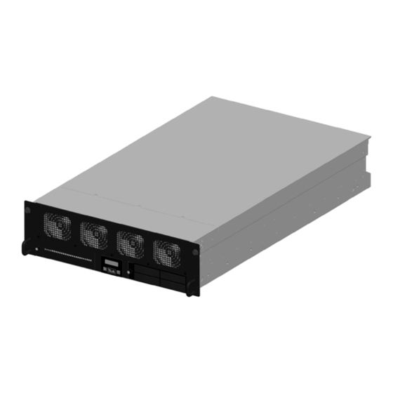
Bull servers for business and scientific applications are based upon the MESCA architecture (Multiple Environments on a SCalable Architecture), leveraging the latest generation of Intel Itanium processors. The NovaScale 9006 Server provides up to 4 processor sockets, 32 memory DIMMs, 8 hard disk drives and 6 PCI-e boards per 3U. Figure 5. -
Page 25: Reliability, Availability, Serviceability (Ras)
Serial Number 2.2. Reliability, Availability, Serviceability (RAS) The NovaScale 9006 Server is designed to meet the highest quality standards and support a comprehensive offering of Reliability, Availabitlity and Serviceability (RAS) features, guaranteeing maximum system uptime. The main RAS features supported by the server are: •... -
Page 26: Features
2.3. Features The main features offered by NovaScale 9006 Servers are: Intel Itanium Processor Family (IPF) Architecture • Modularity, predictable performance, and growth High Availability • Component redundancy • Capacity to isolate or replace a faulty component without service disruption •... -
Page 27: Components, Controls And Leds
2.4. Components, Controls and LEDs Components The following diagram shows an exploded view of server drawer components: Label Description Quantity Fan Unit Up to 8 PCIe Separator PCIe Card Up to 6 Power Supply Unit 2 or 3 Dummy CSI Interconnect Board (DSIB) Prepositioner Embedded Management Board (OPMA) I/O Legacy Board (ILB) -
Page 28: Figure 7. Server Drawer Leds And Buttons - Front View
Simultaneously lights the BLUE ID LED (G) on the rear of the server drawer. Disk Cooling LED Flashing Amber: disk cooling fault. Disk Activity LED Flashing Green: disk active. Figure 7. Server drawer LEDs and buttons - Front view NovaScale 9006 Server - Installation Guide... -
Page 29: Figure 8. Server Drawer Leds And Buttons - Rear View
Control and LEDs (Rear view) Label Name Description Return to Defaults Returns the Embedded Management Controller settings to default Button values. Power Supply Still Green: power supply unit powered up. Unit LED Flashing Green: power supply unit on stand-by. Flashing Amber: power supply unit fault. Ethernet Activity Indicates network activity status. -
Page 31: Chapter 3. Installing The Server In The Cabinet
Chapter 3. Installing the Server in the Cabinet This chapter explains how to install a NovaScale 9006 Server drawer in a Bull Cabinet. It includes the following topics: • Cabinet Requirements, on page 3-2 • Installing the Server Drawer Rack-Mount Kit, on page 3-3 •... -
Page 32: Figure 9. Positioning The Server Drawer In The Cabinet
3.1. Cabinet Requirements The server drawer is designed for installation in a 42U or 19U Bull Cabinet. Before installing the server drawer, please check that the following points: • A 3U free space must be available in the cabinet per server drawer. If you are only installing one server drawer in the cabinet, you are advised to used position 16-17-18U. -
Page 33: Table 1. Rack-Mount Kit Items
3.2. Installing the Server Drawer Rack-Mount Kit The server drawer is delivered with a rack-mount kit for installation in a Bull Cabinet. The rack-mount kit contains the items listed in the following table: Quantity Item Slide Rail Assembly Slide Rail Bracket... -
Page 34: Figure 10. Slide Rail Assembly: Parts A And B
Figure 11. Slide rail assembly: Disassembling the drawer and rack rails 2. Repeat Step 1 for the second slide rail assembly. NovaScale 9006 Server - Installation Guide... -
Page 35: Figure 12. Installing Drawer Rails On The Server Drawer
3.2.2. Mounting the Rails on the Server Drawer Once the rails have been disassembled, you can proceed to mount the drawer rails on the server drawer. 1. Align the drawer rail mount holes with the four mount holes along the left side of the drawer, taking care to place the right-angle rail bend (A) against the front panel of the server drawer. -
Page 36: Figure 13. Installing The Cable Hanger On The Drawer
6. Check that the two red stop pins (Mark B) are retracted. If this is not the case, pull the stop pins outward and turn 90° to block them in the retracted position. Figure 14. Retracting cable hanger stop pins NovaScale 9006 Server - Installation Guide... -
Page 37: Figure 15. Fully Extending The Left Rack Rail
3.2.3. Mounting the Rails on the Cabinet Rack Once the rails have been disassembled and the drawer rail has been mounted on the server, you can proceed to mount the cabinet rails on the cabinet rack. Note The rack rails each comprise a fixed part and a mobile part. 1. -
Page 38: Figure 17. Pre-Installing Support Brackets On The Fixed Part Of The Rack Rail
Insert the bracket stub (A) in the rack mount hole. b. Secure the rail into place by tightening the M5x16 screw and D5 tapered washer (B). Figure 18. Securing the rack rail to the cabinet rack - 1 NovaScale 9006 Server - Installation Guide... -
Page 39: Figure 19. Securing The Rack Rail To The Cabinet Rack
5. Secure the rack rail into place on the rear cabinet rack: a. With the front bracket secured to the front cabinet rack (A), as explained in Step 4, slide the rear bracket to the rear cabinet rack (B). b. Secure the rear bracket to the rear cabinet rack (C), as explained in Step 4. c. -
Page 40: Figure 20. Installing Cable Hanger Brackets To The Rear Cabinet Rack
(centre to centre - 57 mm). These cage nuts will be used to lock the drawer into position on the cabinet rack. Figure 21. Installing the two cage nuts on the front cabinet rack 8. Repeat Steps 1 to 7 for the right rack rail. 3-10 NovaScale 9006 Server - Installation Guide... -
Page 41: Figure 22. Fully Extending And Locking Rack Rails
3.3. Installing and Securing the Server Drawer in Position DANGER The Server Drawer weighs 40 kg when fully populated. 3 people are required to unpack it and install it in the cabinet. 1. From the front of the cabinet, pull the rack rails fully forward until they lock into place. Figure 22. -
Page 42: Figure 23. Installing The Server Drawer In The Cabinet
The server drawer can no longer be freely pulled forward. Figure 23. Installing the server drawer in the cabinet 3. Raise the two thumb levers on the rail assemblies. Figure 24. Raising the thumb levers 3-12 NovaScale 9006 Server - Installation Guide... -
Page 43: Figure 25. Securing The Server Drawer To The Cabinet Rack
4. Push the server drawer fully backward until it is flush with the cabinet frame. 5. Tighten the two captive screws (A) securing the server drawer to the cabinet rack. Label Description Server drawer captive screws Figure 25. Securing the server drawer to the cabinet rack 6. -
Page 45: Chapter 4. Connecting And Testing The Server
Chapter 4. Connecting and Testing the Server This chapter explains how to connect a NovaScale 9006 Server drawer to the site power supply and to the enterprise LAN. It includes the following topics: • Connecting the Server to the Power Distribution Unit(s) (PDU), on page 4-2 •... -
Page 46: Figure 27. Power Supply Minimum Configuration (Rear View)
4.1. Connecting the Server to the Power Distribution Unit(s) (PDU) The NovaScale 9006 Server can be configured with two Power Supplies (PS) (standard configuration), or with three Power Supplies (redundant configuration). The connections to the Power Supplies are located on the rear of the Server Drawer. -
Page 47: Figure 29. Connecting Power Supplies Redundant Configuration (Rear View)
According to configuration, two (standard) or three (redundant) power cords are used to connect the NovaScale 9006 Server power supplies to the Power Distribution Units (PDU). Figure 29. Connecting Power Supplies redundant configuration (rear view) Chapter 4. Connecting and Testing the Server... -
Page 48: Figure 30. Powering On The Server From The Lcp
The Server Drawer is now connected to the site power supply. 4. Check the server status display sequence on the LCP screen: a. “Bull Architect of an Open World”. b. MAC address, IP address, name in scrolling mode on the first line. -
Page 49: Checking Power Status On The Local Control Panel (Lcp) Display
System Event Log (SEL) messages (See Viewing and Clearing the System Event Log (SEL), on page 5-8). Fore more information see Troubleshooting the NovaScale 9006 Server Drawer in the NovaScale 9006 Service Guide , 86A768FA. Chapter 4. -
Page 50: Figure 31. Powering Off The Server From The Lcp
Check that the following server status indications are displayed on the LCP display screen (B): MAC address, IP address, name in scrolling mode on the first line DEEP STDBY message on the second line Green light ON and BLINKING LCP screen backlight OFF NovaScale 9006 Server - Installation Guide... -
Page 51: Figure 32. Connecting The Server To The Enterprise Lan
4.6. Connecting the Server to the Enterprise LAN The connections to the network are located on the rear of the drawer. From the rear of the Server Drawer, connect the ETH MNG port (RJ45 outlet) (A) to the Enterprise LAN. (If the Administration and Enterprise are managed through different networks, use the Administration network). -
Page 52: Table 3. Embedded Management Board Factory-Default Network Parameters
Two buttons located at the rear of the Server Drawer allow to force a hard reset or to restore the default values of the configuration data. Refer to Components, Controls and LEDs, on page 2-5 NovaScale 9006 Server - Installation Guide... -
Page 53: Figure 34. Device Setup Screen - Psetup
Prerequisites • The server is connected to the site power supply. • You have access to two RJ45 Ethernet network outlets connected to the same network subnet (if you use Remote access). • The DHCP server (where applicable) is installed on the same network subnet. •... -
Page 54: Figure 35. Dhcp Auto-Configuration - Psetup
7. Click Query Device. The current network settings appear in the Network Configuration box. Figure 35. DHCP auto-configuration - psetup 4-10 NovaScale 9006 Server - Installation Guide... -
Page 55: Figure 36. Example Of A Static Ip Address Configuration - Psetup
11.If required, to back up configuration data, use the KiraTool Environment utility provided on the Resource and Documentation CD. Refer to Backup Configuration Data in Appendix A. of the NovaScale 9006 Server Hardware Console User's Guide. Chapter 4. Connecting and Testing the Server... -
Page 57: Chapter 5. Completing The Installation Report
Chapter 5. Completing the Installation Report This chapter explains how to check the hardware correct operation in the following topics: • Starting the Hardware Console, on page 5-2 • Powering On the Server, on page 5-3 • Viewing Monitoring Sensors, on page 5-5 •... -
Page 58: Figure 37. Authentication Page Description
This will enable you to interface easily with the iCare Console. If you lose your account details and are unable to connect to the console, please contact your Customer Service Representative. NovaScale 9006 Server - Installation Guide... -
Page 59: Powering On The Server
What To Do if an Incident Occurs? If you cannot connect to the console or if the web pages are displayed incorrectly, one of the following problems may be the cause: • Network failure. • Incorrect network settings. • Incorrect browser settings (proxy configuration). 5.2. -
Page 60: Figure 38. Standard Power Operations Box - Power On
Standard Power Operations Box Note: For details on other power management features, see the NovaScale 9006 Server Hardware Console User's Guide. Power On button Launches the power up sequence. During this sequence, hardware is powered up from the standby power mode to the main power mode and the Operating System is booted. -
Page 61: Viewing Monitoring Sensors
5.3. Viewing Monitoring Sensors The server is equipped with various sensors that monitor: • Power status • Presence, absence, redundancy of components • Voltage values • Temperature values • Fan speed Procedure 1. From the Monitoring tab, click System Health > Sensors to display the Sensor Status page. - Page 62 This component is operating correctly. No problem has been detected. CRITICAL This component is not operating correctly. A problem has been detected. Immediate preventive or corrective action is required. Table 4. Status Icons Description NovaScale 9006 Server - Installation Guide...
-
Page 63: Table 5. Sensor Status
Sensor Status Page - Icons, Values and Readings Icon Type Name Status Reading • No reading System ACPI • S0/G0: working ACPI Pwr State Power State • S4/S5: soft off • No reading • Device Present • Device Absent Power Supply PS_X •... -
Page 64: Viewing And Clearing The System Event Log (Sel)
It is strongly recommended to empty this log regularly, using the Clear button, so that the latest events can be logged. Note that cleared entries are deleted and cannot be retrieved. Prerequisites • Viewing: none. • Clearing: you have Alert Settings & Clear SEL permission. NovaScale 9006 Server - Installation Guide... -
Page 65: Figure 40. System Event Log Page
Use the Clear button to empty the log. Entries are deleted and cannot be retrieved. Note SEL messages and associated operation to recover are explained in the NovaScale 9006 Service Guide in the Troubleshooting the NovaScale 9006 Server Drawer chapter. 5.5. -
Page 66: Figure 41. Board & Security Messages Page
This log can record up to 1.000 events. Once this limit is reached, the arrival of new messages will automatically delete the oldest messages in the log. Related Topics • Setting Up Board and Security Messaging Policies, in the NovaScale 9006 Server Hardware Console User's Guide 5-10 NovaScale 9006 Server - Installation Guide... -
Page 67: Powering Off The Server
5.6. Powering Off the Server The system can be powered off from the Power Management page Standard Operations box. mportant The Power status display is not updated dynamically, therefore displayed status may not reflect actual status and the Power Off button may not be enabled although the system is powered up. -
Page 68: Figure 42. Standard Power Operations Box - Power Off
Standard Power Operations Box Note: For details on other power management features, see the NovaScale 9006 Server Hardware Console User's Guide. Power On button Accessible only when the system is powered off. Power Off button Requests the Operating System to perform a graceful power down. -
Page 69: Appendix A. Lcp Displaymessages
Appendix A. LCP DisplayMessages This section describes the messages that may be displayed on the Local Control Panel (LCP). The LCP displays two lines (L1 and L2) of 16 characters (C1 to C16) each. C10 C11 C12 C13 C14 C15 C16 First line (L1) The fist line shows the following information in scrolling mode: <MAC Address>... -
Page 71: Table 7. Novascale 9006 Server Specifications
Appendix B. NovaScale 9006 Server Specifications The following Web site may be consulted for general site preparation information: http://www.cs.bull.net/aise Dimensions / Weight Height 3U - 13,35 cm (13.97 in) Width 44 cm (17.32 in) Depth 75 cm (29.52 in) Weight (maximum) -
Page 73: Glossary
Glossary AC: Alternating Current generated by the power supply. See DC. ACPI: Advanced Configuration and Power Interface. An industry specification for the efficient handling of power consumption in desktop and mobile computers. ACPI specifies how a computer's BIOS, operating system, and peripheral devices communicate with each other about power usage. Address: A label, name or number that identifies a location in a computer memory. - Page 74 Cell: The smallest set of hardware components allocated to a single OS. A cell is functionally defined by: - the number of available processors - memory capacity - I/O channel capacity. CellBlock: A group of interconnected cells within a single domain. See Central Subsystem. Central Subsystem: A group of interconnected cells gathered within a single domain.
- Page 75 D2D: DC to DC converter. DC: Direct Current generated by the power supply. See AC. Default Setting: The factory setting your server uses unless instructed otherwise. Density: The capacity of information (bytes) that can be packed into a storage device. Device Driver: A software program used by a computer to recognize and operate hardware.
- Page 76 EMI: Electro-Magnetic Interference. EPROM: Erasable Programmable Read‐Only Memory. A type of memory device that is used to store the system BIOS code. This code is not lost when the computer is powered off. ERC: Error and Reset Controller. This controller allows PAM software to control error detection and reset propagation within each pre-defined CSS partition.
- Page 77 Flash EPROM: Flash Erasable Programmable Read‐Only Memory. A type of memory device that is used to store the the system firmware code. This code can be replaced by an updated code from a floppy disk, but is not lost when the computer is powered off. Firewall: A set of related programs, located at a network gateway server, that protects the resources of a private network from users from other networks.
- Page 78 HMMIO Space: High Memory IO Space. HPB: Hot Plug Board. This board provides an interlock switch on each IO Box PCI slot for hot- swapping PCI boards. See P-HPB. HPC: High Performance Computing. Hot plugging: The operation of adding a component without interrupting system activity. Hot swapping: The operation of removing and replacing a faulty component without interrupting system activity.
- Page 79 IOR: I/O Board Riser. The IOR provides: - I/O controller Hub - USB ports - 10/100/1000 Ethernet controller - Video controller - Serial / debug port IP: Internet Protocol. The protocol by which data is sent from one computer to another via the Internet. Each computer (known as a host) on the Internet has at least one IP address that uniquely identifies it from all other computers on the Internet.
- Page 80 Locking: Means of functionally limiting access to certain hardware elements. Locked hardware elements can no longer be accessed by the current domain, but are still physically available for use by other domains. Previously locked elements can be unlocked so that they can be accessed by the domain. LPT1 or LPT2: The name assigned to a parallel port to specify its address.
- Page 81 NFS: Network File System. A proprietary distributed file system that is widely used by TCP/IP vendors. Note: NFS allows different computer systems to share files, and uses user datagram protocol (UDP) for data transfer. NMI: Non-Maskable Interrupt. NUMA: Non Uniform Memory Access. A method of configuring a cluster of microprocessors in a multiprocessing system so that they can share memory locally, improving performance and the ability of the system to be expanded.
- Page 82 PAM tree, e.g.: PAM:/CELLSBLOCK_<NAME>/MODULE_x/QBB_y/CPU_y. QBB: Quad Brick Board. The QBB is the heart of the Bull NovaScale Server, housing 4 Itanium R 2 processors and 16 DIMMs. Each QBB communicates with other CSS Module components via 2 high-speed bidirectional Scalability Port Switches.
- Page 83 S@N.IT: SAN Administration Tool. SAL: System Abstraction Layer. Firmware that abstract system implementation differences in IA-64 platform. See also PAL. SAN: Storage Area Network. A high-speed special-purpose network that interconnects different kinds of data storage devices with associated data servers on behalf of a larger network of users. SAPIC: Streamlined Advanced Programmable Interrupt Controller message.
- Page 84 Socket: Central Processing Unit mutlticore interface. Each socket can house 1 or 2 processor cores. See Microprocessor and CPU. Source: Each message refers to a source (the resource that generated the message) and a target (the component referred to in the message). This feature can be allows messages to be filtered according to one or more Source string(s) and is particularly useful for debugging and troubleshooting.
- Page 85 USB: Universal Serial Bus. A plug-and-play interface between a computer and add-on devices. The USB interface allows a new device to be added to your computer without having to add an adapter card or even having to turn the computer off. VCC: Voltage Continuous Current.
- Page 86 g‐14 Product Name - Manual Type...
-
Page 87: Index
Index Availability, 2-3 connecting, 4-8 connecting to, 4-7 Laser safety, xii LEDs, server, 2-5 Board and security messages, viewing, 5-9 BSM, 2-4 mc-setup tool, 4-8 Mounting, rails Cabinet cabinet, 3-7 rails, mounting, 3-7 server drawer, 3-5 requirements, 3-2 Cable hanger, installing, 3-6 Clearing, system event log, 5-8 Components, server, 2-5 Connecting... - Page 88 Unlocking, stop pins, 3-13 unpacking, 1-4 Unpacking, server, 1-4 Server drawer securing, cabinet, 3-11 starting, 4-4 Serviceability, 2-3 Viewing Specifications, 1-2, B-1 board and security messages, 5-9 Starting system event log, 5-8 console, 5-2 server, 4-4 x‐2 NovaScale 9006 Server - Installation Guide...
- Page 90 Bull Cedoc 357 avenue Patton BP 20845 49008 Angers Cedex 01 FRANCE REFERENCE 86 A1 69FA 00...
Need help?
Do you have a question about the NovaScale 9006 and is the answer not in the manual?
Questions and answers