Table of Contents
Advertisement
Quick Links
Advertisement
Table of Contents

Related Manuals for Bull NovaScale 5xx5


Summary of Contents for Bull NovaScale 5xx5
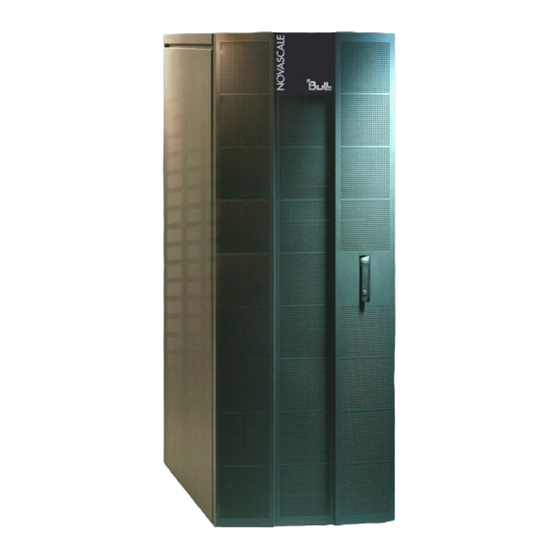
- Page 1 NovaScale 5xx5 Installation Guide REFERENCE 86 A1 40EM 06...
- Page 2 BLANK...
- Page 3 NOVASCALE NovaScale 5xx5 Installation Guide Hardware September 2007 BULL CEDOC 357 AVENUE PATTON B.P.20845 49008 ANGERS CEDEX 01 FRANCE REFERENCE 86 A1 40EM 06...
- Page 4 Linus Torvalds. The information in this document is subject to change without notice. Bull will not be liable for errors contained herein, or for incidental or consequential damages in connection with the use of this material.
-
Page 5: Table Of Contents
............Bull Novascale Server Overview . - Page 6 ........2-16 Powering Up the NovaScale 5xx5 SMP Server Domain .....
- Page 7 ........2-35 NovaScale 5xx5 SMP Servers - Operating System Setup ....
- Page 8 Index ..............Installation Guide...
-
Page 9: List Of Figures
Figure 1. Bull NovaScale Server cabinets .......... - Page 10 Figure 47. PAP unit free Ethernet port ........... . . 2-32 Figure 48.
- Page 11 List of Tables Table 1. PAM Tree nodes ............. 2-10 Table 2.
- Page 12 Installation Guide...
-
Page 13: Intended Readers
This guide is intended for use by qualified personnel in charge of setting up and starting NovaScale 5xx5 Servers for the first time. It will also prove useful to qualified personnel in charge of setting up and starting Bull NovaScale 7000 Series and Bull NovaScale 9000 Series servers for the first time. -
Page 14: Related Publications
This guide is intended for use by all personnel and trade representatives involved in the site preparation process. User's Guide, 86 A1 41EM explains how to use NovaScale 5xx5 Servers. This guide is intended for use by Customer Administrators and Operators. Maintenance and Service Guide, 86 A7 42EM explains how to maintain, service, and upgrade NovaScale 5xx5 Servers. -
Page 15: Regulatory Specifications And Disclaimers
Regulatory Specifications and Disclaimers Declaration of the Manufacturer or Importer We hereby certify that this product is in compliance with European Union EMC Directive 2004/108/CE, using standards EN55022 (Class A) and EN55024 and Low Voltage Directive 2006/95/CE, using standard EN60950. The product has been marked with the CE Mark to illustrate its compliance. -
Page 16: Federal Communications Commission (Fcc) Statement
Federal Communications Commission (FCC) Statement Note: This equipment has been tested and found to comply with the limits for a Class A digital device, pursuant to Part 15 of the FCC Rules. These limits are designed to provide reasonable protection against harmful interference when the equipment is operated in a commercial environment. -
Page 17: Definition Of Safety Notices
Definition of Safety Notices DANGER A Danger notice indicates the presence of a hazard that has the potential of causing death or serious personal injury. CAUTION: A Caution notice indicates the presence of a hazard that has the potential of causing moderate or minor personal injury. -
Page 18: Laser Safety Information
Data Integrity and Verification Warning: Bull NovaScale Servers are designed to reduce the risk of undetected data corruption or loss. However, if unplanned outages or system failures occur, users are strongly advised to check the accuracy of the operations performed and the data saved or transmitted by the system at the time of outage or failure. -
Page 19: Environmental Standards
• EN61000-3-2, Limit for Harmonic Current Emissions • EN61000-3-3, Voltage Flicker • FCC Part 15 Class A North America • ICES-003 Issue 3 Class A Bull NovaScale Blade servers also comply with standards: • Japan: IEC 1000-3-2 • Australia / New Zealand: IEC 60950 • Taiwan: BSMI Approval •... -
Page 20: Protection Against Electrostatic Discharges
Protection against Electrostatic Discharges CMOS (Complementary Metal Oxide Semiconductor) technology is highly sensitive to electrostatic discharges. The use of conductive antistatic flooring is strongly recommended. Maintenance personnel must wear wrist-straps before handling electronic equipment. A ground socket is provided in each cabinet. Shocks and Vibrations The servers comply with standards: IEC 60068-1... -
Page 21: Pollution Limits
• ISO 4871 • ISO 9295 • ISO 9296 • IEC 61260 • IEC 60651 (Bull NovaScale 5xx5 Series & Bull NovaScale 5xx5 Series) • IEC 61672-1 (Bull NovaScale 4000 Series) • IEC 61672-2 (Bull NovaScale 4000 Series) Operating LwAd Acoustical Power •... - Page 22 Installation Guide...
-
Page 23: Installation Flowchart
Installation Flowchart This flowchart summarizes main installation and setup procedures. Unpacking the Server Step • Inspect server packing • Remove server packing • Inspect the server • Unload the server cabinet(s) and accessories • Store packing items Installing and Securing the Cabinet Step •... - Page 24 Connecting the Server to the Power Supply Step • Mount power supply cable sockets • Connect the server power cables to the dedicated power supply Powering up the Server Step • Power on the server to the standby mode • Launch PAM software •...
- Page 25 Connecting the Server to the Enterprise LAN and Connecting External Devices Step • Connect the server to the Enterprise LAN • Connect external peripherals (storage, modem, ...) Confirming Correct Installation Step • Test network connections • Test Autocalls • Record site data •...
- Page 26 xxiv Installation Guide...
-
Page 27: Chapter 1. Delivery
Chapter 1. Delivery This chapter explains delivery unpacking and inspection procedures. It includes the following topics: • Overview, on page 1-2 • General Recommendations, on page 1-7 • Unpacking the Server Cabinet, on page 1-8 • Inspecting the Server before Unloading the Cabinet, on page 1-8 •... -
Page 28: Bull Novascale Server Overview
Extended Configurations Several Bull NovaScale Servers may be administered through a single instance of PAM software. Cluster Configurations Several Bull NovaScale Servers may be grouped to act like a single system, enabling high availability, load balancing and parallel processing. Installation Guide... -
Page 29: Server Features
Server Features The main features of Bull NovaScale Servers are: Intel Itanium Processor Family architecture: Modularity, predictable performance and growth High availability: Component redundancy Capacity to isolate or replace a faulty component without service disruption Global and unified system visibility... -
Page 30: Server Hardware
Server Hardware Note: Abbreviations and acronyms are documented in the Glossary. Main server hardware components are: Central SubSystem Module (CSS Module) Main server hardware components are housed in the CSS Module. For easy access and servicing, the CSS Module is composed of three interconnected units: Front Unit Core Unit Rear Unit... -
Page 31: Rear Unit
Midplane Fan & Logistics Board (MFL) 16 Fans and various logistics components are implemented on the MFL. The MFL is connected to both the MIO and the MQB. Fanboxes 8 Fanboxes, each housing 2 fans, provide redundant cooling. Rear Unit IO board Compact (IOC) The IOC provides 4 x PCI -X and 2 x PCI-Express buses and a PCI Hot Plug Board (HPB). -
Page 32: Conformance To Standards
• IPMI (Intelligent Platform Management Interface) • EFI (Extended Firmware Interface) • SMBIOS (System Management BIOS) • DIG64 (Developer Interface Guide for Intel Itanium Architecture) Windows Bull NovaScale Servers conform to the standards set out in the Windows Hardware Design Guide. Installation Guide... -
Page 33: General Recommendations
General Recommendations Bull NovaScale Servers are delivered rack-mounted and pre-cabled in one or more high or low cabinets, according to the version chosen. Site preparation must be completed by the pre-arranged delivery date. Any delay due to non-completion of the site by the pre-arranged date will be considered as the Customer's responsibility. -
Page 34: Unpacking The Server Cabinet
Unpacking the Server Cabinet Instructions on how to unpack cabinets for Bull NovaScale Servers and peripheral devices are set out in document Bull 1300H/L & 1100H/L Cabinets, 86 A1 91EM. Warning: The server must not be unpacked before it has reached room temperature (24 hours in the Computer Room). -
Page 35: Removing Css Module Brackets And Installing Stoppers
Removing CSS Module Brackets and Installing Stoppers Each Bull NovaScale Server CSS module is equipped with two yellow shipping brackets at the front and two yellow shipping brackets at the rear of the cabinet. Once the server has been installed and correctly secured, you must remove all shipping brackets and install the stoppers supplied in the Open Me First box. -
Page 36: Installing Stoppers
Installing Stoppers Four stoppers, complete with captive screws, are supplied with each CSS module and must be installed once shipping brackets have been removed. The two narrow stoppers are installed on the front cabinet frame and the two deep stoppers are installed on the rear cabinet frame. -
Page 37: Inspecting Internal Components And Cabling
Inspecting Internal Components and Cabling A thorough visual inspection of internal components and cabling should now be carried out before powering up the server. CAUTION: If the inspection indicates an unacceptable safety condition, the condition must be corrected before powering up the server. 1. -
Page 38: Getting To Know The Server
Getting to Know the Server NovaScale 5085 Partitioned Server Note: Server components and configuration may differ according to the version chosen. The server is delivered rack-mounted and pre-cabled in a low or high cabinet, typically containing the following components: XXXXXXXX XXXXXXXXXXXXXXXXXXXX Front Rear... -
Page 39: Novascale 5165 Partitioned Server
NovaScale 5165 Partitioned Server Note: Server components and configuration may differ according to the version chosen. The server is delivered rack-mounted and pre-cabled in a high cabinet, typically containing the following components: XXXXXXXX XXXXXXXXXXXXXXXXXXXX Front Rear CSS module with core unit, power supply and AC power cable, including: 8 U x 8 U x IOL board - legacy ports... -
Page 40: Novascale 5245 Partitioned Server
NovaScale 5245 Partitioned Server Note: Server components and configuration may differ according to the version chosen. The server is delivered rack-mounted and pre-cabled in a high cabinet, typically containing the following components: XXXXXXXX XXXXXXXXXXXXXXXXXXXX Front Rear CSS module with core unit, power supply and AC power cable, including: 8 U x 8 U x IOL board - legacy ports... -
Page 41: Novascale 5325 Partitioned Server
NovaScale 5325 Partitioned Server Note: Server components and configuration may differ according to the version chosen. The server is delivered rack-mounted and pre-cabled in two high cabinets, typically containing the following components: Main Cabinet XXXXXXXX XXXXXXXXXXXXXXXXXXXX Front Rear CSS module with core unit, power supply and AC power cable, including: 8 U x 8 U x IO Box (IOC) with:... -
Page 42: Figure 10. Novascale 5325 Partitioned Servers Components - Example
I/O Cabinet PAP unit with CD-ROM writer, FDD and 2 disks 2 PDU(s) with AC power cable 2 FC disks 3x2 U KVM extender (remote) Figure 10. NovaScale 5325 Partitioned Servers components - example 1-16 Installation Guide... -
Page 43: Server Components
Server Components Note: Server components and configuration may differ according to the version chosen. The server includes the following components: • CSS module, on page 1-18 • Integrated console, on page 1-20 • Integrated Platform Administration Processor (PAP) unit, on page 1-19 •... -
Page 44: Central Subsystem (Css) Module
Central Subsystem (CSS) Module The CSS module houses main hardware components: Front Rear Front 1 or 2 QBB (Quad Brick Board) subset(s): Each QBB subset houses: • 1 mother board • 2 memory boards • 1 to 4 processors • 16 DIMMs 1 or 2 Internal Peripheral Drawer(s): Each drawer houses: •... -
Page 45: Integrated Platform Administration Processor (Pap) Unit
Integrated Platform Administration Processor (PAP) Unit The PAP unit is linked to the server via the Platform Management Board (PMB). It hosts Platform Administration Software (PAM). According to version, the PAP unit is located in the center of a high cabinet or at the top of a low cabinet. PAP Unit 1U •... -
Page 46: Integrated Console
Integrated Console According to version, the console is located in the center of a high cabinet or at the top of a low cabinet. The inegrated console contains the keyboard, monitor and touch pad used for local access to the server and to the Platform Administration Processor (PAP) Unit. •... -
Page 47: Keyboard / Video / Mouse (Kvm) Switch
Keyboard / Video / Mouse (KVM) Switch The KVM Switch allows the use of the integrated console for the local server and the local Platform Administration and Maintenance console. 8-Port KVM Switch • 8 ports • 1 power cable Figure 14. 8-port KVM switch features 16-Port KVM Switch •... -
Page 48: Fda 1X00 Fc Disk Rack
FDA 1x00 FC Disk Rack Optionally, the FDA 1x00 FC Disk Rack is delivered with pre-installed system disks (two RAID#1 and one spare disk per domain). Empty slots can be used for data disks. According to version, the Disk Rack is located in the main or I/O cabinet. •... -
Page 49: Fda 1X00 Fc Extension Disk Rack
FDA 1x00 FC Extension Disk Rack The FDA 1x00 FC Extension Disk Rack offers15 empty slots for data disks. According to version, the Disk Rack is located in the main or I/O cabinet. • 15 slots • 2 power cables (redundant power supply) Figure 19. -
Page 50: Ethernet Hub
Ethernet Hub The optional Maintenance LAN Ethernet Hub is used to connect PMB, PAP Unit and external FDA FC Disk Rack Ethernet ports. Ethernet Hub 8 ports 1 power cable 1 power bar Figure 20. Ethernet hub features USB Modem The optional USB modem is used to transmit Autocalls to the Remote Maintenance Center, if the Customer's maintenance contract includes the Autocall feature. -
Page 51: Chapter 2. Setup Procedure
Chapter 2. Setup Procedure Important: Certain features described in this chapter are reserved for partitioned servers and extended systems and/or to systems connected to a Storage Area Network (SAN). This chapter explains the procedures required to set up and start the server for the first time. It includes the following topics: •... -
Page 52: Accessing Server Components
Accessing Server Components Opening the Front Door Tools Required: • Cabinet key Figure 23. Opening the front door 1. Unlock the front door with the key. 2. Pull out the locking mechanism and turn to open. 3. Open the door as required. Closing the Front Door 1. -
Page 53: Opening / Closing The Integrated Console
Opening / Closing the Integrated Console The server is equipped with an integrated console for local administration and maintenance operations. Figure 24. Integrated console example To open the integrated console: 1. Slide the console forward until it clicks into place. 2. -
Page 54: Checking Pmb Code Wheel Settings
Checking PMB Code Wheel Settings Up to 16 Central Subsystems can be linked, via Platform Management Boards (PMBs) to a single PAP unit, to provide a single point of administration and maintenance. Each PMB is equipped with two code wheels used to identify each Central Subsystem and each CSS module in your configuration. -
Page 55: Checking Server Cabling
Checking Server Cabling Important: Cables to external peripherals must NOT be connected before powering up the server for the first time. These cables must only be connected once server operation has been checked. All internal cabinet cables are pre-connected before shipping. However, cables may become loose during shipping and you are advised to check for loose cables before powering up the server. -
Page 56: Checking Server Operation
Checking Server Operation Once the server has been installed and powered up, correct operation must be checked. Important: The server must be fully checked with factory default data. See the booklet delivered with the system 24 hours before the Read Me First scheduled installation date for factory default data. - Page 57 To complete installation, you need to open a Customer Administrator and a Support Administrator PAM session. To open a Customer Administrator PAM session: 1. From the Microsoft Windows desktop, double-click the Internet Explorer icon (http://localhost/PAM). 2. When prompted, request the Customer Administrator to enter the default User Name and Password: Customer Administrator User Name...
-
Page 58: Pam User Interface
PAM User Interface The PAM user interface is divided into three areas in the browser window: a Status pane, a PAM Tree pane, and a Control pane. Status pane, on page 2-9 PAM Tree pane, on page 2-10 Control pane, on page 2-9 Figure 26. -
Page 59: Checking Server Status Via Pam
Checking Server Status via PAM The PAM user interface allows you to check system status at a glance. If the Functional Status icon in the Status pane and the CSS Availability Status bar are green, the server is ready to be powered up. -
Page 60: Css Availability Status Bar
CSS Availability Status Bar The CSS availability status bar reflects the operational status of the data link(s) between the Platform Management Board (PMB) embedded in each CSS Module and the PAP Unit. Each CSS module is represented by a zone in the status bar. •... -
Page 61: Figure 29. Pam Tree Toolbar
PAM Tree Toolbar The PAM Tree toolbar, located at the top of the PAM Tree, is used to refresh, expand, or collapse the tree display. Toolbar Buttons Explanation Refresh /rebuild the PAM Tree to view changes. Expand the complete tree. Collapse the complete tree. -
Page 62: Toggling The Local / Integrated Console Display
The KVM Switch allows the integrated console to be used as the local server domain and local PAP unit console. KVM ports are configured as shown in Table 2. NovaScale 5xx5 SMP Server 8-port KVM Switch Console Display... -
Page 63: Testing Css Module Ring Connections
Testing CSS Module Ring Connections If the server is equipped with more than one CSS module, you are advised to perform a Ring Test to check CSS module ring connections (clocks, XSP links, sidebands) before proceeding to power up server domains. Important: •... -
Page 64: Figure 31. Default Domain Loaded
5. When requested, click Yes to confirm. The default domain is loaded in the Control pane. Figure 31. Default domain loaded 6. From the Support Administrator PAM Tree, click Domain Manager to open the Control pane. 7. Select the default domain and click Advanced to open the Advanced Properties dialog. Figure 32. - Page 65 10.Click Power On to power up the server domain and associated hardware components. When prompted, select View Power-On Logs to monitor test progress. The following message is displayed in the Domain State field: Powering on (test) The test takes 2 to 3 minutes to complete. The last message (Step 99) in the Power-On Logs information box indicates test result status: •...
-
Page 66: Powering Up / Down Server Domains
Status pane - the server can be powered up. To power up / down the server, see: • Powering Up / Down the NovaScale 5xx5 Partitioned Server Domains, on page 2-18 Powering Up the NovaScale 5xx5 SMP Server Domain NovaScale 5xx5 SMP Servers are designed to operate as single SMP systems and are delivered with one pre-configured domain. -
Page 67: Shutting Down / Restarting The Server
4. Follow the power-on steps displayed in the Domain State box, until RUNNING is displayed. Figure 34. Domain state 5. Toggle the local / integrated console from the PAP unit display to the server display. See Toggling the Local / Integrated Console Display, on page 2-12. 6. -
Page 68: Powering Up Novascale 5Xx5 Partitioned Server Domains
Powering Up NovaScale 5xx5 Partitioned Server Domains According to version, NovaScale 5xx5 Partitioned Servers are designed to operate as up to eight hardware-independent SMP systems, or domains. For easy configuration and optimum use of the physical and logical resources required for simultaneous operation, domains are defined via the PAM Domain Scheme wizard. -
Page 69: Figure 35. Domain Schemes List Dialog
To power up / down server domains: Note: If an error dialog box appears during these sequences, see Managing Domains in the User's Guide. 1. From the Customer Administrator PAM Tree, click Domain Manager to open the Control pane. You are invited to load a Domain Scheme. 2. -
Page 70: Figure 36. Domain Manager Control Pane - Example With 4 Domains
Functional status icon CSS availability status indicator (GREEN) Operating system type Figure 36. Domain Manager Control pane - example with 4 domains 5. Click Multiple Power. The Multiple Power Domains On/Off dialog opens. 6. Click Power On All → Execute to simultaneously power on the domains and associated hardware components. -
Page 71: Shutting Down / Restarting The Server
12.Repeat Steps 10 and 11 for each domain. 13.Check the Operating System environment pre-installed on each domain. 14.Shut down each Operating System to power down the corresponding domain to the stand-by mode. 15.Toggle the local / integrated console to the PAP unit display. INACTIVE is displayed in the Domain State boxes and the Power ON button is accessible for each domain. -
Page 72: Changing The Istorage Manager User Name And Password
Changing the iStorage Manager User Name and Password FDA 1x00 FC and FDA 2x00 FC subsystems are delivered with iStorage Manager (iSM) software for integrated monitoring and centralized management. The iSM Server / Client utility is installed on the PAP Unit desktop. The Customer can install iSM Client on any standard PC running under Microsoft Windows (2000 or later). -
Page 73: Changing The S@N.it Password
Changing the S@N.IT Password FDA 1x00 FC and FDA 2x00 FC subsystems are delivered with S@N.IT software for integrated monitoring and centralized management. The S@N.IT Server / Client utility is installed on the PAP Unit desktop. The Customer can install S@N.IT Client on any standard PC running under Microsoft Windows (2000 or later). Before using S@N.IT, the Customer is advised to replace the factory default sanadmin User Password. -
Page 74: Completing Pap Unit Configuration
Completing PAP Unit Configuration Important: Before proceeding to complete PAP Unit configuration: • Refer to the PAM Writing Rules, on page B-3 • Check Regional, Date/Time, and Time Zone settings Changing the Default PAP Unit Name Request the Customer to change the default PAP unit name <PAP> from the Microsoft Windows Network configuration utility. -
Page 75: Figure 39. Pap Configuration Wizard Dialog
5. Check that the release type is correct: NovaScale 5xx5 Servers The MonoDomain radio button must be highlighted. NovaScale 5xx5 Partitioned Servers The MultiDomain radio button must be highlighted. Note: If the release type is not correct, select the required release type and click Apply change. -
Page 76: Figure 41. Network Configuration Dialog
a. Click the Configure the Network button to configure Customer Enterprise LAN settings and to change the default factory PAP unit network setting. Figure 41. Network configuration dialog b. Click the Change Windows Administrator Password button to change the PAP unit Customer Administrator password. -
Page 77: Figure 43. Pam Configuration Via Web Site Dialog
c. Click the Configure PAM Software via the PAM Web Site button to open a Support Administrator PAM session to complete Customer Information, Autocalls and Central Subsystem configuration. Figure 43. PAM configuration via Web site dialog d. Click the Configure SAN Software Identities button to change the default S@N.IT password and the ISM user name and password. - Page 78 Warning: Changes to Central Subsystem configuration are hazardous and must not be performed until the server has been fully tested. If the Customer wants to rename the Central Subsystem, this entails removing the existing Central Subsystem and adding a new Central Subsystem with the required name.
-
Page 79: Configuring Customer Information
Configuring Customer Information Customer information is used by PAM software: • for the PAM Tree display: the name entered in the Site name field will be used for the PAM tree root node - the default name is NovaScale.. • to complete Customer Service Engineer Intervention Reports, •... -
Page 80: Configuring Autocalls
Configuring Autocalls The Autocall feature is part of the BULL Remote Maintenance contract. It is used to automatically route system events to the Remote Maintenance Center. Full details are given in the BULL Remote Maintenance Guide. If the Customer's maintenance contract includes the Autocall feature, configure Autocall parameters as follows: Figure 46. - Page 81 9. Return to the PAP Unit Microsoft Windows desktop to complete remote maintenance setup as explained in the BULL Remote Maintenance Guide. Note: Connection of the USB modem required for the Autocall feature is explained in Connecting the USB Modem and External Devices, on page 2-45.
-
Page 82: Connecting The Pap Unit To The Customer's Enterprise Lan
Connecting the PAP Unit to the Customer's Enterprise LAN CAUTION: Remote access via the Web is a potential security hazard. Customers are strongly advised to protect their systems with up-to-date protection devices such as virus-prevention programs and firewalls, and to maintain a detailed record of authorized users. Once PAP unit configuration is complete, it can be connected to the Customer's Enterprise LAN. -
Page 83: Connecting To The Pam Web Site From A Remote Computer/Workstation
Connecting to the PAM Web Site from a Remote Computer/Workstation Important: For optimum security, before connecting to PAM from a remote computer, you are advised to disconnect from your local Windows session on the PAP unit by clicking Start → Log Off. The PAM Software utility can be accessed from any PC running Microsoft Windows with the Internet Explorer (6 or later) browser installed and/or from any workstation running Linux with the Mozilla (1.6 or later) browser installed. -
Page 84: Enabling Remote Access To Ism On The Client Computer
Enabling Remote Access to iSM on the Client Computer FDA 1x00 FC and FDA 2x00 FC subsystems are delivered with iStorage Manager (iSM) for integrated monitoring and centralized management. The iSM Server / Client utility is installed on the PAP Unit desktop. The Customer can install iSM Client on any standard PC running under Microsoft Windows (2000 or later). -
Page 85: Completing Operating System Setup
For further information about the server booting environment, see Using EFI Utilities in the User's Guide. To complete Operating System setup, see: • NovaScale 5xx5 SMP Servers - Operating System Setup, on page 2-36 • NovaScale 5xx5 Partitioned Server - Operating System Setup, on page 2-40 2-35... -
Page 86: Novascale 5Xx5 Smp Servers - Operating System Setup
NovaScale 5xx5 SMP Servers - Operating System Setup An Operating System instance is pre-installed on the domain boot disk: 0LU0 = LUN device located in Module0_DIB0 or connected to Module0_IOC0 Before proceeding to complete setup on the domain: 1. From the Customer Administrator PAM Tree, click Domain Manager. -
Page 87: Microsoft Windows Setup
Microsoft Windows Setup Warning: Most of the options selected and validated during the setup sequence can be modified. However, special attention is to be paid when selecting and validating the Licensing Mode (Per Seat / Per Server). If selected and validated, the "Per Server" Licensing Mode option CAN be modified. -
Page 88: Linux Redhat Setup
Linux RedHat Setup 1. Select the Linux RedHat domain in the Control pane scheme and click Power On to power up the domain and associated hardware components. 2. Toggle the local / integrated console from the PAP unit display to the domain display. See Toggling the Local / Integrated Console Display, on page 2-12. -
Page 89: Novell Suse Setup
Novell SuSe Setup 1. Select the Linux SuSe domain in the Control pane scheme and click Power On to power up the domain and associated hardware components. 2. Toggle the local / integrated console from the PAP unit display to the domain display. See Toggling the Local / Integrated Console Display, on page 2-12. -
Page 90: Novascale 5Xx5 Partitioned Server - Operating System Setup
NovaScale 5xx5 Partitioned Server - Operating System Setup An Operating System instance is pre-installed on each domain boot disk (EFI LUN): 0LU0 = LUN device located in Module0_DIB0 or connected to Module0_IOC0 0LU1 = LUN device located in Module0_DIB1 or connected to Module0_IOC1... -
Page 91: Microsoft Windows Setup
Microsoft Windows Setup Warning: Most of the options selected and validated during the setup sequence can be modified. However, special attention is to be paid when selecting and validating the Licensing Mode (Per Seat / Per Server). If selected and validated, the "Per Server" Licensing Mode option CAN be modified. -
Page 92: Linux Redhat Setup
Linux RedHat Setup 1. Select the first Linux RedHat domain in the Control pane scheme and click Power On to power up the domain and associated hardware components. 2. Toggle the local / integrated console from the PAP unit display to MyOperations-1 or MyOperations-2 or MyOperations-3 or MyOperations-4 display, as required. -
Page 93: Novell Suse Setup
Novell SuSe Setup 1. Select the first Linux SuSe domain in the Control pane scheme and click Power On to power up the domain and associated hardware components. 2. Toggle the local / integrated console from the PAP unit display to MyOperations-1 or MyOperations-2 or MyOperations-3 or MyOperations-4 display, as required. -
Page 94: Connecting The Server To The Enterprise Lan
IOL board for remote operation. LAN port Figure 48. 10/100/1000 Mb/s LAN port To connect server domain(s) to the Enterprise LAN: NovaScale 5xx5 Partitioned Servers 9. Locate the corresponding IOL board: MyOperations-1: Module0, IOC0, IOL0 MyOperations-2: Module0, IOC1, IOL1 MyOperations-3: Module1, IOC0, IOL0... -
Page 95: Connecting The Usb Modem And External Devices
Connecting the USB Modem and External Devices Connecting the USB Modem If the Customer's maintenance contract includes the Autocall feature, connect the USB modem as follows: 1. Connect the modem cable equipped with a USB connector to the USB port on the rear of the PAP unit. -
Page 96: Testing Network Connections
Testing Network Connections Network connections to the PAP unit and to server domains can be tested from a remote workstation connected to the same network by launching a PING command. Note: PAP unit setup is described in Completing PAP Unit Configuration, on page 2-24. Windows... -
Page 97: Renaming A Central Subsystem
Renaming a Central Subsystem Note: Central Subsystem configuration is reserved for Customer Service Engineers. The Central Subsystem may be renamed to suit Customer requirements. Changes to Central Subsystem configuration entail removing the existing Central Subsystem from the configuration and adding a new Central Subsystem to the configuration with the name chosen by the Customer. -
Page 98: Figure 50. Central Subsystem Node
Example of PMB code wheel settings for a system with 3 cabinets, each containing 2 modules: Cabinet 1 Cabinet 2 Cabinet 3 Cabinet Hexadecimal Code (0 to F) CSS Module_0 Hexadecimal Code (0 to F) CSS Module_1 Hexadecimal Code (0 to F) Table 3. -
Page 99: Setting Up Pap Unit Users
PAP Customer Administrator user group. For further details about user management, refer to the Microsoft Windows documentation on the Bull NovaScale Server System Resource CD. Note: You are advised to change the temporary Administrator password (administrator) used for setup purposes and to maintain a detailed record of authorized users. -
Page 100: Table 4. User Access To Pam Features
PAM Tools Associated Actions Synchronize domains View/load a domain configuration scheme Add domains to the current domain configuration Replace the current domain configuration Delete domains from the current domain configuration Save the current domain configuration snapshot Power on/off and reset domains Domain Manager Forcibly power off domains Perform a domain memory dump... -
Page 101: Initializing The Pap Unit Backup Disk
Initializing the PAP Unit Backup Disk The PAP Unit is delivered with two RAID 1 (hard mirror) disks installed and a third spare disk. Now that the server has been installed and is operational and the PAP Unit and PAM software have been customized, you should now initialize the backup disk. -
Page 102: Figure 52. Displaying Pap Unit Disk Configuration
2. Display PAP Unit disk configuration. Figure 52. Displaying PAP Unit disk configuration 3. Check that backup disk configuration is the same as that of the two original disks installed in the PAP Unit. 4. Flush caches by powering down the PAP Unit. 5. -
Page 103: Figure 55. Blank Disk Building Process
7. Reboot the PAP Unit by pressing the Power On switch (A) in the above figure. 8. Wait for Windows ready and launch Adaptec Storage Manager. 9. Insert the blank (third) disk and monitor the building process. Figure 55. Blank disk building process 2-53 Setup Procedure... -
Page 104: Backing Up And Restoring Pam Configuration Files
Windows Task Scheduler to save PAM configuration data to a removable media or to a network directory for rapid restoration in the event of a PAP unit failure. To ensure carefree, reliable and regular configuration data backup, the Bull NovaScale Server Resource CD contains two scripts, PamBackupData.js and PamRestoreData.js, that can be scheduled to run via the Microsoft Windows Task Scheduler to save and restore PAM configuration data. - Page 105 2-55 Setup Procedure...
-
Page 106: Restoring Pam Configuration Data
Restoring PAM Configuration Data Warning: The same PAM software release must be deployed on the PAP unit and on the backup PC to allow data restoration. See Deploying a New PAM Release, on page 0 and Activating a PAM Version, on page 0. PAM releases use the same data directory to ensure configuration consistency. -
Page 107: Appendix A. Specifications
Appendix A. Specifications • NovaScale 5085 Server Specifications, on page A-2 • NovaScale 5165 Server Specifications, on page A-4 • NovaScale 5245 Server Specifications, on page A-6 • NovaScale 5325 Server Specifications, on page A-8 Server Specifications... -
Page 108: Novascale 5085 Server Specifications
NovaScale 5085 Server Specifications NovaScale 5085 Servers are delivered rack-mounted in 40U or 19U cabinets. The following web site may be consulted for general site preparation information: http://www.cs.bull.net/aise. Cabinet Dimensions / Weight Unpacked Packed 1300H 1300H Height: 195.5 cm (77.0 in) Height: 200.0 cm (78.7 in) -
Page 109: Table 5. Novascale 5085 Server Specifications
Power Cables PDU-2-4-M-32A AC (32A) 1 per PDU Cable type 3 x AWG10 ( 3 x 6 mm / #10US) Connector type IEC60309-32A It is mandatory for power lines and terminal boxes to be located within the immediate vici- nity of the system and to be easily accessible. Each power line must be connected to a se- parate, independent electrical panel and bipolar circuit breaker. -
Page 110: Novascale 5165 Server Specifications
NovaScale 5165 Server Specifications NovaScale 5165 Servers are delivered rack-mounted in 40U or 19U cabinets. The following web site may be consulted for general site preparation information: http://www.cs.bull.net/aise. Cabinet Dimensions / Weight Unpacked Packed 1300H 1300H Height: 195.5 cm (77.0 in) Height: 200.0 cm (78.7 in) -
Page 111: Table 6. Novascale 5165 Server Specifications
° ° Acoustic Power at Room Temperature +20 C (+68 System Running System Idle Lw(A) 6.3 Bels Lw(A) 6.1 Bels Power Cables PDU-2-4-M-32A AC (32A) 1 per PDU Cable type 3 x AWG10 (3 x 6 mm / #10US) Connector type IEC60309-32A It is mandatory for power lines and terminal boxes to be located within the immediate vici- nity of the system and to be easily accessible. -
Page 112: Novascale 5245 Server Specifications
NovaScale 5245 Server Specifications NovaScale 5245 Servers are delivered rack-mounted in 40U cabinets. The following web site may be consulted for general site preparation information: http://www.cs.bull.net/aise. Cabinet Dimensions / Weight Unpacked Packed 1300H 1300H Height: 195.5 cm (77.0 in) Height: 200.0 cm (78.7 in) -
Page 113: Table 7. Novascale 5245 Server Specifications
Power Cables PDU-2-4-M-32A AC (32A) 1 per PDU Cable type 3 x AWG10 (3 x 6 mm / #10US) Connector type IEC60309-32A It is mandatory for power lines and terminal boxes to be located within the immediate vici- nity of the system and to be easily accessible. Each power line must be connected to a se- parate, independent electrical panel and bipolar circuit breaker. -
Page 114: Novascale 5325 Server Specifications
NovaScale 5325 Server Specifications NovaScale 5325 Servers are delivered rack-mounted in 40U cabinets. The following web site may be consulted for general site preparation information: http://www.cs.bull.net/aise. Cabinet Dimensions / Weight Unpacked Packed 1300H 1300H Height: 195.5 cm (77.0 in) Height: 200.0 cm (78.7 in) -
Page 115: Table 8. Novascale 5325 Server Specifications
Power Cables PDU-2-4-M-32A AC (32A) 1 per PDU Cable type 3 x AWG10 (3 x 6 mm / #10US) Connector type IEC60309-32A It is mandatory for power lines and terminal boxes to be located within the immediate vici- nity of the system and to be easily accessible. Each power line must be connected to a se- parate, independent electrical panel and bipolar circuit breaker. - Page 116 A-10 Installation Guide...
-
Page 117: Appendix B. Conversion, Keyboard, And Writing Tables
Appendix B. Conversion, Keyboard, and Writing Tables Imperial to Metric 1 inch (") 2.54 cm (centimeters) 1 foot (') (12 inches) 30.48 cm 1 yards (yd) (3 feet) 0.91 m (meters) 1 mile (mi) (1760 yards) 1.6093 km (kilometers) 1 pound (avdp) (lb) 0.5 kg (kilograms) 1 ounce (avdp) (oz) 28.4 g (grams) -
Page 118: Azerty/Qwerty Keyboard Lookup Table
AZERTY/QWERTY Keyboard Lookup Table Figure 56. AZERTY keyboard Figure 57. QWERTY keyboard Installation Guide... -
Page 119: Pam Writing Rules
PAM Writing Rules Illegal Characters The following table lists the illegal characters that must not be used in PAM identifiers. Illegal Characters à, é, è, ù, ^, ¨ Accentuated letters Slash Backslash " Double quote Simple quote Inverted comma & Ampersand Plus Asterisk... -
Page 120: String Lengths
Two versions of PAM software can be installed and used indifferently on the same machine: each new version is installed in a new directory. • SiteRoot: Contains site data file paths. Site data remains valid when the PAM software version changes. Registry keys are generally stored under: HKEY_LOCAL_MACHINE\SOFTWARE\BULL\PAM Installation Guide... -
Page 121: Glossary
Glossary BIOS: Basic Input / Output System. A program stored in flash EPROM or ROM that controls the system startup process. AC: Alternating Current generated by the power BIST: Built-In Self-Test. See POST. supply. See DC. Bit: Derived from BInary digiT. A bit is the smallest ACPI: Advanced Configuration and Power Interface. - Page 122 CMCV: Corrected Memory Check Vector. Density: The capacity of information (bytes) that can be packed into a storage device. CMOS: Complementary Metal Oxide Semiconductor. Device Driver: A software program used by a A type of low-power integrated circuits. System computer to recognize and operate hardware. startup parameters are stored in CMOS memory.
- Page 123 DRAM: Dynamic Random Access Memory is the Event channel: Defines how the Event Manager most common type of random access memory sends an event message. An event channel is one (RAM). of: HISTORY (the message is logged in a history file), EMAIL (the message is sent to an e-mail address), WEB (the message is stored for analysis from the PAM web user interface), SNMP (the...
- Page 124 FCAL: Fibre Channel Arbitrated Loop. Global MCA: Machine Check Abort is visible to all processors, in a multiprocessor system and will FCA: Fibre Channel Adapter. force all of them to enter machine check abort. FCBQ: Fan Control Board for QBB. GUI: Graphical User Interface.
- Page 125 IOL: I/O Board Legacy. The IOL provides: - I/O controller Hub - USB ports - 10/100/1000 Ethernet controller I2C: Intra Integrated Circuit. The I2C (Inter-IC) bus is - Video controller a bi-directional two-wire serial bus that provides a - Serial / debug port communication link between integrated circuits (ICs).
- Page 126 LD: Logical Disk. A Storeway FDA 1x00/2x00 MCA: Machine Check Abort. logical disk (or LUN) is visible to the OS as a Disk. See also Local MCA and Global MCA. See LUN and PD (Physical Disk). Memory: Computer circuitry that stores data and LED: Light Emitting Diode.
- Page 127 Multitasking: The ability to perform several tasks PAM Tree pane: One of the three areas of the PAM simultaneously. Multitasking allows you to run web page. Server hardware presence and multiple applications at the same time and functional status are displayed in the PAM Tree exchange information among them.
- Page 128 Interrupt Controller message. QBB: Quad Brick Board. The QBB is the heart of the SBE: Single Bit Error. Bull NovaScale Server, housing 4 Itanium processors and 16 DIMMs. Each QBB Scheme: Configuration file ensuring optimum use communicates with other CSS Module components...
- Page 129 SSI: Server System Infrastructure. SIO: Server I/O / Super I/O. Status Pane: One of the three areas of the PAM Shell: The Shell is the layer of programming that web page. Provides quick access to CSS Module understands and executes the commands a user availability status, server functional status, and enters.
- Page 130 UML: Unified Modeling Language. A standard VxWORKS: Platform Management Board Operating notation for the modeling of real-world objects as a System. first step in developing an object-oriented design methodology. UPS: Uninterruptible Power Supply. A device that allows uninterrupted operation if the primary power WAN: Wide Area Network.
- Page 131 Index Electrostatic discharges, xviii Enterprise LAN connecting PAP unit, 2-32 Access, front door, 2-2 connection, 2-44 Autocalls Environmental standards, xvii configuring, 2-30 FTP parameters, 2-30 Ethernet hub, 1-24 testing, 2-46 Ethernet ports, 1-18, 1-19 Back Up, PAM software, 2-54 FC storage subystems, password, changing, 2-22 FDA 1300 disk rack, 1-22 FDA 2300 FC disk rack, 1-22 FDD, 1-19...
- Page 132 domain, 2-16 getting to know, 1-12 Operating System, completing setup, 2-35 inspecting, 1-8 Operating system, setup restarting, 2-17, 2-21 completing, 2-36, 2-40 shutdown, 2-17, 2-21 Microsoft Windows, 2-37, 2-41 Server components accessing, 2-2 CD-ROM drive, 1-19 console, 1-20 core unit, 1-18 details pane, 2-9 CSS module, 1-18 status pane, 2-9...
- Page 133 weight, A-1 User interface, PAM, 2-8 System components, DVD/CD-ROM drive, 1-18 VGA port, 1-18 Toolbar, PAM, 2-11 Writing rules USB modem, connecting, 2-45 illegal characters, B-3 USB ports, 1-18 string lengths, B-4 User group, PAP, 2-49 Index...
- Page 134 Installation Guide...
- Page 135 If you require a written reply, please include your complete mailing address below. NAME : Date : COMPANY : ADDRESS : Please give this technical publication remarks form to your BULL representative or mail to: ept. Bull - Documentation D 1 Rue de Provence BP 208...
- Page 136 : The latest revision will be provided if no revision number is given. [ _ _ ] NAME: Date: COMPANY: ADDRESS: PHONE: FAX: E-MAIL: For Bull Subsidiaries: Identification: For Bull Affiliated Customers: Customer Code: For Bull Internal Customers: Budgetary Section: For Others: Please ask your Bull representative.
- Page 137 BLANK...
- Page 138 BULL CEDOC 357 AVENUE PATTON B.P.20845 49008 ANGERS CEDEX 01 FRANCE REFERENCE 86 A1 40EM 06...
- Page 139 Utiliser les marques de découpe pour obtenir les étiquettes. Use the cut marks to get the labels. NOVASCALE NovaScale 5xx5 Installation Guide 86 A1 40EM 06 NOVASCALE NovaScale 5xx5 Installation Guide 86 A1 40EM 06 NOVASCALE NovaScale 5xx5 Installation Guide...
Need help?
Do you have a question about the NovaScale 5xx5 and is the answer not in the manual?
Questions and answers