
Related Manuals for Milton Roy LMI P1


Summary of Contents for Milton Roy LMI P1
- Page 1 LMI ELECTRONIC DOSING PUMPS Code : P1 Basic manual Instruction supplement Spare parts list for drive assembly Declaration « CE » of conformity List of « Technical assistance » and « spare parts » departments 07/98...
- Page 2 INSTRUCTION MANUAL FOR INSTALLATION, OPERATING, AND MAINTENANCE. LMI ELECTRONIC DOSING PUMPS Diaphragm liquid end Basic manual This manual should be made available to the person responsible for installation, operating and maintenance. Date : 02/2012 Ref : 160.0101.001 Rev. D Replaces Rev. 0 09/98...
- Page 4 CONTENTS I – DESCRIPTION I – 1. Unpacking I – 2. Description I – 3. Accessories I – 4. Precautions II – INSTALLATION II – 1. Hydraulic installation II – 2. Electrical installation III – START UP III – 1. Priming III –...
- Page 5 Installation Always comply with local regulations and requirements. Always adhere to your local plumbing codes and requirements. Be sure installation does not constitute a cross connection. Check local plumbing codes for guidelines. Milton Roy Europe is not responsible for improper installations.
- Page 6 CAUTION: CHEMICAL AND INFLAMMABLE PRODUCTS: Take all the precautions necessary when performing work on equipment that is dosing chemical and/or inflammable products. Contact your local Milton Roy Europe distributor for more information. Earth leakage protection CAUTION: It is essential to install an earth leakage circuit breaker calibrated on the basis of the electrical values noted on the equipment plate.
- Page 7 PART I – DESCRIPTION This manual addresses the installation, maintenance and troubleshooting procedures for electronic dosing pumps. An instruction supplement and a liquid end sheet complete this manual. Please read them carefully before installing your pump. I – 1. UNPACKING The packaging must be carefully examined on receipt in order to ensure that the contents have not...
- Page 8 1. Anti-syphon (automatic) Output adjustment controls Prevents syphoning when pumping downhill or According to pump type, output adjustment controls are into a vacuum. available : 2. Back pressure (automatic) • Stroke adjustment Supply approximately 1,7 bar back pressure to prevent over pumping when little or no system Each pump is equipped with a stroke adjustment.
- Page 9 PART II – INSTALLATION II – 1. HYDRAULIC INSTALLATION Flooded suction The pump is mounted at the base of the storage tank. The pump can be mounted in one of two ways : This installation is the most trouble-free, and is recommended for very low outputs, solutions that •...
- Page 10 • Tank mount. The pump may be mounted on a molded tank. Tanks from 60 to 1000 liters are available for this utilisation. Solution tank Foot valve (equipped with strainer) Pump Flow Injection check valve Ceramic weight 50 mm space for sediment accumulation Fig.
- Page 11 • Pump location Remove the plugs which protect the head Locate pump in an area convenient to solution tank and connections and valves. electrical supply. • Do not use pliers or pipe wrench on coupling The pump should not be subjected to ambient nuts or fittings.
- Page 12 Injection check valve Use Teflon tape Do not use Teflon tape ± 30° variation acceptable Reducing bushing ½ ‘’ Pipe cross section Fig. 2.2b : Injection check valve II – 2. ELECTRICAL INSTALLATION OVER-VOLTAGE LMI pumps include a Varistor vonnected on the supply Check the specifications of the pump and compare voltage terminals.
- Page 13 PART III – START UP Pumps are shipped from the factory with water in the 7. The volume and the time unit are known. Calculate pump head to aid in priming. After a long storage, refill the output. If the output is too low or too great, adjust the pump head with water or solution compatible with speed and or stroke, estimating required correction.
- Page 14 III – 5. PRESSURE CONTROL III – 4. VOLUMETRIC CALIBRATION IN EXTERNAL MODE Adjust pressure control (B7 - C7 series) : while unit is running, turn pressure control knob fully clockwise then 1. Since pump output is governed by an external device turn slowly counter-clockwise until unit just begins to such as Flowmeter-pulser, Liquitron™...
- Page 15 IV – MAINTENANCE IV – 1. SPARE PARTS REPLACEMENTS WARNING : Always wera protective clothing, face shield, safety glasses and gloves when performing any maintenance or replacement on your pump. LMI metering pumps are designed for trouble-free operation, yet routine maintenance of elastomeric parts is essential for optimmum performance.
- Page 16 Ball, seal ring and injection check valve spring IV – 2. CHECKING PUMP FOR PROPER replacement or set of cartridges replacement ZEROING (STROKE KNOB) (depending on model) 1. With pump running, turn stroke knob counter- Refer to the spare parts list for the proper sparte parts clockwise toward zero or end of black or red band.
- Page 17 • Air leak on suction side. Check for pinholes, cracks. Replace if necessary. IV – 3. TROUBLESHOOTING Leakage at tubing Pump will not prime • • Worn tubing ends. Pump not turned on or plugged in. Cut tubing about 25 mm (1’’) off tubing and then Turn on pump/plug in pump.
- Page 18 • Little or no pressure at injection point. Excessive pump output If pressure at injection point is less than 1,5 bar (25 • Syphoning. Pumping downhill without a 4-FV. psi), an 4-FV should be installed. Move injection point to a pressurized location or •...
- Page 19 Instruction Supplement LMI PUMP SERIES P1 Foot valve Injection check valve Ceramic weight Discharge tubing Suction tubing Spacer E.P.U. Suction fitting Metering pump housing Return line (pressure relief) Speed knob Pump head Stroke knob 4-Function valve (option) Power cord Coupling nut Metering pump component diagram Date : 10.98 REF.
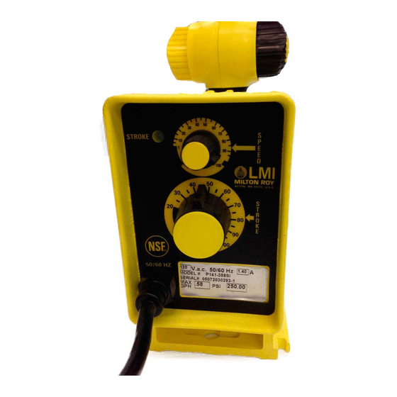
- Page 20 Identification plate Stroke knob Speed knob Stroke light Control panel detail Potentiometer Stroke led Pulser assembly Power cord Mov/cap assembly EPU assembly P12x, P13x : cut 1 resistor Other P1 : leave both resistors Blue Brown GRN/YEL Green/yellow Yellow Wiring diagram LMI PUMP SERIES P1...
- Page 21 TECHNICAL CHARACTERISTICS P12x P13x P14x P15x P16x P18x Output - max. (l/h) 0.75 - min (ml/h) 2.25 15.2 Max. pressure (bar) 10.3 17.3 Stroke capacity (ml) - min. 0.07 0.13 0.07 0.13 0.25 0.40 - max. 0.22 0.44 0.37 0.63 1.27 2.00 Stroke frequency (cps/mn)
- Page 22 Liquid End Sheet When pumping solutions, make certain that all tubing is securely attached to the fittings. It is recommended that tubing or pipe lines be shielded to prevent possible injury in case of rupture or accidental damage. Always wear protective clothing and face shield when working on or near your metering pump. Flexible connection without connection Nozzle Mounting Steps : Manual mounting Tubing Connections...
- Page 23 Foot Valve/Suction Tubing Multi-Function Valve Installation Installation To install the multi-function valve, remove the yellow screw cap on the top of the pump head and screw in The Foot Valve acts as a check valve to keep the pump the valve so that it contacts the seal ring. An additional primed in suction lift applications.
- Page 24 Liquid End Parts List 1 Flapper valve 2 Injection check valve body 3 Injection check valve spring 4 Check valve ball 5 Seal ring 6 Cartridge valve 7 Cartridge valve o-ring 8 Cartridge valve washer 9 Valve seat 10 Clamp ring 11 Ferrule 12 Clamp sleeve 13 Tubing adapter...
- Page 25 Start-Up/Priming for Pump Negative pressure Supplied with Multi-Function Anti-Syphon at discharge closes Knob diaphragm and Valve prevents syphoning. Read this entire section completely before proceeding. Pump discharge stroke When all precautionary steps have been taken, the lifts diaphragm to allow for fluid flow.
- Page 26 DECLARATION "CE" DE CONFORMITE Nous, déclarons que le matériel désigné ci-après a été conçu et fabriqué suivant les directives et spécifications suivantes : Directive basse tension 2006/95/EEC Directive CEM 2004/108/EEC "EC" DECLARATION OF CONFORMITY We, certify that the equipment designated below has been designed and manufactured in accordance with the specifications of the following : Low voltage Directive 2006/95/EEC EMC Directive 2004/108/EEC...
- Page 27 GUARANTEE The vendor guarantees his products according to the Milton Roy Europe. general conditions of sale. The guarantee for components and sub-assemblies not fabricated by the vendor is limited tothat given by the supplier. The vendor’s guarantee only covers the replacement or the repair, at his cost and in his factory, of all parts acknowledged by his technical services as being defective due to an error in conception, of material or of execution.
- Page 28 Tel.: +34 91 4741914 - Fax : +34. 91 3459707 - E-mail: info@sdm-sistemas.com C/ Embajadores, 100 28012 Madrid - ESPANA www.sdm-sistemas.com ITALIA / MALTA Milton Roy Italia Srl Tel.: +39.(0)39.65.78.505 - Fax: +39 (0)39 60.56.906 E-mail: sergio.testa@miltonroy-europe.com Centro Direzionale Colleoni Via Paracelso, 16 Palazzo Andromeda Ingresso 2 20041 Agrate Brianza (Ml) - ITALIA www.miltonroy-europe.com...
Need help?
Do you have a question about the LMI P1 and is the answer not in the manual?
Questions and answers