Subscribe to Our Youtube Channel
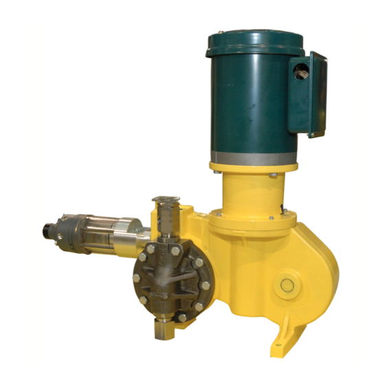
Summary of Contents for Milton Roy mROY
- Page 1 ® Pneumatic Capacity Control Instruction Manual Manual No. : 53871 Rev. : 01 Rev. Date : 05/2019...
- Page 3 Contact your distributor or sales representative for further information. Head Loss / Over Pressure Protection / Back Pressure-Anti-Siphon Valve: • Milton Roy metering pumps are positive displacement. Head loss is not applicable to the pump. • To ensure safe operation of the pump it is recommended that some type of safety/pressure relief valve be installed to protect the piping and other system components from failing due to excessive pressure.
-
Page 4: Table Of Contents
TABLE OF CONTENTS SECTION 1 - PNEUMATIC CAPACITY CONTROL . . . . . . . . . . . . . . . . . . . . . . . . . . . . . . . . . . . . . . . . . . . . . . . . 5 SECTION 2 - DISASSEMBLY AND ASSEMBLY PROCEDURE . -
Page 5: Section 1 - Pneumatic Capacity Control
The supply air (Ps) is routed internally to the pilot positioner mounted on the mRoy pump. The valve and it is also routed unrestricted, internally assembly consists of three major sections as... - Page 6 SECTION 1 - PNEUMATIC CAPACITY CONTROL In operation, an increase in instrument air pressure A decrease in instrument air pressure moves the (Pi) upsets the balanced forces and moves the diaphragm assembly to the right which seats the diaphragm assembly to the left. This lifts the pilot head of the pilot valve and lifts the pilot valve stem valve above its seat to reduce the air pressure drop off the exhaust seat.
-
Page 7: Section 2 - Disassembly And Assembly Procedure
SECTION 2 - DISASSEMBLY AND ASSEMBLY PROCEDURE 2.1 DISASSEMBLY 2.3 CALIBRATION AFTER ASSEMBLY 1. Disconnect the supply and instrument air To calibrate the pneumatic capacity control pressure lines. after reassembly, apply an instrument air signal corresponding to 100% capacity setting. Remove 2. -
Page 8: Section 3 - General Performance
SECTION 3 - GENERAL PERFORMANCE The pneumatic capacity control assembly will It should be noted that the instrument air pressure provide accurate incremental adjustment in both is applied to a closed chamber in the positioner directions as a linear function of the applied valve so that the regulator or instrument system instrument air pressure. -
Page 9: Section 4 - Operating Specification
SECTION 4 - OPERATING SPECIFICATIONS Supply Pressure Regulated 40-100 psi. 3-15 psi standard, other pressure ranges available on CDA (Instrument) Pressure Range special order. Pump Capacity Variation over Instrument 0-100% rated capacity. Pressure Range Minimum Pressure Change Required to Reset 0.20 psi or 0.13% of full range pressure. -
Page 10: Figure 1. Assembly Pneumatic Capacity Control
CLIP 1/4 E-RING EXTERNAL 1145 - (ACTUATOR) PLUG 1 NPT LVLSL HEXS 18-8SS PLUG 1/2 NPT LVLSL HEXS 18-8SS ADAPTER MOUNT FLANGE MROY A PNEU. O-RING .921 X .139 BUNA N 1000 INT TOOTH LOCK WASHER #6 Z PL 1010... -
Page 11: Section 5 - Table Of Equivalents
SECTION 5 - TABLE OF EQUIVALENTS 1.0333 kilograms/square centimeter 1 atmosphere Equals 101.33 kilopascals 1.0135 bars 1 Btu/hour Equals 0.2928 Watts Degrees Fahrenheit Equals 1.8° Celsius + 32 1 Engler degree Equals 7.45 square millimeters/second 30.48 centimeters 1 foot Equals 12 inches 1 Ford cup #4 Equals... - Page 12 We are committed to a world of sustainable progress and enduring results. info@miltonroy.com MROY is a registered trademark of Milton Roy, LLC. www.miltonroy.com ® © 2019 Milton Roy, LLC.


Need help?
Do you have a question about the mROY and is the answer not in the manual?
Questions and answers