Sign In
Upload
Download
Table of Contents
Contents
Add to my manuals
Delete from my manuals
Share
URL of this page:
HTML Link:
Bookmark this page
Add
Manual will be automatically added to "My Manuals"
Print this page
×
Bookmark added
×
Added to my manuals
Manuals
Brands
Milton Roy Manuals
Water Pump
MILROYAL B
Instruction manual
Milton Roy MILROYAL B Instruction Manual
Disc diaphragm liquid end
Hide thumbs
Also See for MILROYAL B
:
Instruction manual
(20 pages)
1
2
Table Of Contents
3
4
5
6
7
8
9
10
11
12
13
14
15
16
17
18
19
20
page
of
20
Go
/
20
Contents
Table of Contents
Troubleshooting
Bookmarks
Table of Contents
Table of Contents
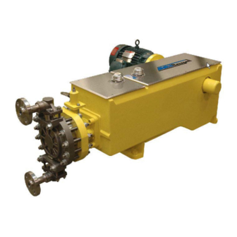
LIST of ILLUSTRATIONS FIGURE 1. MILROYAL Disc Diaphragm
Section 1 - Description
General
Principles of Operation
Safety Precautions
Section 2 - Installation
Unpacking
Conversion Procedures
Milroyal ® a & B
Milroyal
Piping
Piping Concentrated Sulfuric Acid
Suction Lift Conditions
FIGURE 2. Milton Roy Sludge Trap
FIGURE 3. Typical Sludge Trap Installation
Section 3 - Operation
Initial Start-Up
Initial Adjustment
Refill Valve
Maintenance
Hydraulic Oil
Check Valves
Plastic Check Valves
Disassembly
Reassembly
Diaphragm
Reassembly
Spare Parts
Section 4 - Troubleshooting
FIGURE 4. MILROYALB Disc Diaphragm Liquid End Assembly Drawing (C-102-2095-0006)
B Disc Diaphragm Liquid End Assembly Drawing (C-102-2095-0006)
B Disc Diaphragm Liquid End Assembly Drawing Continued (C-102-2095-0006)
C Disc Diaphragm Liquid End Assembly Drawing (C-102-2285-0006)
Figure 5. Milroyal
Figure 4. Milroyal
Figure 5. Milroyalc
C Disc Diaphragm Liquid End Assembly Drawing Continued (C-102-2285-0006)
Advertisement
Quick Links
1
Milroyal ® a & B
2
Initial Start-Up
3
Maintenance
4
Hydraulic Oil
5
Spare Parts
6
B Disc Diaphragm Liquid End Assembly Drawing (C-102-2095-0006)
Download this manual
MILROYAL
Diaphragm Liquid End
Instruction Manual
Manual No : 54145
Rev.
: 00
Rev. Date
: 12/2015
B and C Disc
®
Table of
Contents
Previous
Page
Next
Page
1
2
3
4
5
Advertisement
Table of Contents
Need help?
Do you have a question about the MILROYAL B and is the answer not in the manual?
Ask a question
Questions and answers
Related Manuals for Milton Roy MILROYAL B
Water Pump Milton Roy Milroyal B Instruction Manual
Pneumatic capacity control (20 pages)
Water Pump Milton Roy MILROYAL C Instruction Manual
Disc diaphragm liquid end (20 pages)
Water Pump Milton Roy MILROYAL D Instruction Manual
Drive with packed plunger liquid end high-performance dosing (32 pages)
Water Pump Milton Roy MILROYAL D Instruction Manual
Disc diaphragm. low flow liquid end. (28 pages)
Water Pump Milton Roy MAXROY Series Actuator Capacity Control Manual
(33 pages)
Water Pump Milton Roy MILROYAL G Instruction Manual
(48 pages)
Water Pump Milton Roy maxRoy B Installation, Operation And Maintenance Manual
(66 pages)
Water Pump Milton Roy Primeroyal Instruction Manual
Critical service hpd liquid end (40 pages)
Water Pump Milton Roy MILROYAL Series Actuator Capacity Control Manual
(33 pages)
Water Pump Milton Roy mRoy A Installation, Operation And Maintenance Manual
Metering pump (73 pages)
Water Pump Milton Roy mROY B Manual
Metering pump iom (79 pages)
Water Pump Milton Roy mROY Instruction Manual
Pneumatic capacity control (12 pages)
Water Pump Milton Roy MacRoy Installation, Operation And Maintenance Manual
(66 pages)
Water Pump Milton Roy mRoy XT Installation, Operation And Maintenance Manual
Metering pump (60 pages)
Water Pump Milton Roy Haskel G Series Technical Specifications And Performance Data
6 hp pump (25 pages)
Water Pump Milton Roy GM Series Instruction Manual
(64 pages)
This manual is also suitable for:
Milroyal c
Table of Contents
Save PDF
Print
Rename the bookmark
Delete bookmark?
Delete from my manuals?
Login
Sign In
OR
Sign in with Facebook
Sign in with Google
Upload manual
Upload from disk
Upload from URL


Need help?
Do you have a question about the MILROYAL B and is the answer not in the manual?
Questions and answers