
Subscribe to Our Youtube Channel
Related Manuals for Liebert PDUTM


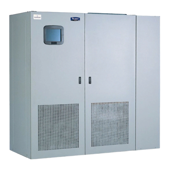
Summary of Contents for Liebert PDUTM
- Page 1 OWER ISTRIBUTION STS2/PDU™ & M NSTALLATION PERATION AINTENANCE ANUAL 250A - 800A Three Phase 60 Hz...
-
Page 2: Ontacting Iebert For Upport
ONTACTING IEBERT FOR To contact Liebert Global Services for information or repair service in the United States, call 1-800-LIEBERT (1-800-543-2378). Liebert Global Services offers a complete range of start-up services, repair services, preventive maintenance plans and service contracts. For repair or maintenance service outside the 48 contiguous United States, contact Liebert Global Services, if available in your area. -
Page 3: Table Of Contents
Power Supply ........ - Page 4 STS2/PDU O NTRODUCTION TO System Description............69 8.1.1 Redundancy .
- Page 5 12.0 OMMUNICATION NTERFACES 12.1 Using the RS-232 Port ............88 12.1.1 Connecting and Using a Terminal .
- Page 6 15.0 VENT ESSAGE 16.0 ............144 AINTENANCE 16.1 Proper Tightening of Nuts and Bolts .
- Page 7 Figure 36 Electrical field connections, 8600A STS2/PDU with left side output breaker....46 Figure 37 Electrical field connections, 800A STS2/PDU interconnect wiring ......47 Figure 38 Electrical field connections, 800A STS2/PDU interconnect wiring, breaker section .
- Page 8 Table 1 Shipping weights (typical) ............4 Table 2 Heat output .
-
Page 9: Save These Instructions
The input sources to the STS2/PDU must be grounded-wye sources. Input sources other than solidly grounded-wye sources may cause damage to the switch. Liebert Corporation neither recommends nor knowingly sells this product for use with life support or other FDA-designated “critical” devices. - Page 10 A thorough equipment inspection and supervised start-up by qualified service personnel are strongly recommended at these times: 1. Before unit is placed into service for the first time 2. After equipment relocation, and 3. After the unit has been de-energized for an extended period of time CAUTION This unit complies with the limits for a Class A digital device, pursuant to Part 15 Subpart J of the FCC rules and EN550022.
-
Page 11: Unpacking And Inspections
• If any damage as a result of shipping is observed, file a damage claim with the shipper within 24 hours and contact your local Liebert representative or Liebert Global Services at 1-800-543-2378 to inform them of the damage claim and the condition of the equipment. -
Page 12: Handling Considerations
1.2.1 Handling Considerations The STS2/PDU is bolted to a wood shipping pallet to allow handling by forklift equipment or a pallet jack. WARNING Exercise extreme care when handling STS2/PDU cabinets to avoid equipment damage or injury to personnel. The cabinet can be safely tilted 15 degrees in any direction by forklift. If moving the unit up a ramp on its casters (if the unit is so equipped) or a pallet jack, ensure that the incline does not exceed 15 degrees. -
Page 13: Location Considerations
OCATION ONSIDERATIONS The STS2/PDU should be placed in a clean, cool and dry location. The 250A unit without an output cabinet requires only front access for installation and maintenance. Both front and side access are required for installation and maintenance of 400-800A units and 250A units with output cabinet. The output cabinet comes factory installed or either the right or left side depending on how it was ordered. -
Page 14: Altitude
Altitude The standard units are designed for full load operation up to 4000 feet (1200m) above sea level. See Figure 1 for recommended deratings for altitudes greater than 4000 feet (1200m). Figure 1 Recommended derating for high altitude operation Operation at full load at a higher altitude can be accommodated in ambient temperatures less than 104°F (40°C) ambient. -
Page 15: Locating The Sts2/Pdu
STS2/PDU OCATING This section provides instructions for leveling the STS2/PDU and anchoring the unit to the floor, should that be required. Anchoring the Unit to the Floor The STS2/PDU can be anchored to the concrete floor to ensure stability for the unit in the event of seismic activity. -
Page 16: Power And Control Wiring
Table 29. The input power busbars are accessible through the front of the unit. Liebert’s 250A units have PEM nut inserts designed to allow one-handed tightening. Busbars in the 400-800A units are supplied with holes to accommodate two-hole lugs. -
Page 17: Figure 3 Typical Sts2/Pdu, One-Line Diagram
Figure 3 Typical STS2/PDU, one-line diagram Figure 4 Typical STS2/PDU, one-line diagram, with dual static switch output circuit breakers (not available on 250A units) Power and Control Wiring... -
Page 18: Figure 5 Typical Sts2/Pdu, One-Line Diagram, With Inline Distribution, Dual Static Switch Output
Figure 5 Typical STS2/PDU, one-line diagram, with inline distribution, dual static switch output circuit breakers Figure 6 Typical STS2/PDU, one-line diagram, with I-Line distribution, dual static switch output circuit breakers The input and output power wire size should be based on the overcurrent protection device, observing the NEC and local codes. -
Page 19: System Grounding
System Grounding Equipment grounding—Grounding is primarily for equipment and personnel safety, although proper grounding also enhances equipment performance. All input and output power feeds must include an equipment grounding means as required by the NEC and local codes. An insulated equipment ground conductor is recommended to run with each input and output power feed. -
Page 20: Power Supply
200V to 600V. The unit is set at the factory to match the nameplate voltage. Field adjust- ments are not necessary. If the unit needs to operate at a voltage other than what is listed on the nameplate, contact Liebert Global Services or your local Liebert representative. Table 6 provides transformer tap information. -
Page 21: Output Power Wiring
Panelboard—designed to accommodate up to 10 plug-in breakers from 100A to 250A. Additionally, 300A to 400A breakers are available on 800A units. For other optional distribution methods, contact your local Liebert representative or call 1-800-LIEBERT. The STS2/PDU distribution may be mounted on either the right or left side at the customer’s option. -
Page 22: Options
All options must be installed by Liebert Global Services or Liebert factory-authorized service provided by a Liebert distributor. The option area and customer control cable area contain hazardous voltages if any of the input sources are on, even when the unit is in bypass. Turn OFF all power sources before installing customer control cables to any option. -
Page 23: Comms Board
SiteLink-12 or SiteLink-4 is required for SiteScan to communi- cate with the STS2/PDU. The Comms Board is equipped with an RS-422 communication port for communication to a Liebert SiteScan monitoring system using a 2-wire twisted pair for reliable communication up to 1000 meters (3281 feet). -
Page 24: Remote Source Selection
Remote Source Selection The Remote Source Selection allows the preferred input source to be chosen from a remote location. A user supplied normally open dry contact allows the user to remotely select a source to be the preferred source in the same process as the local source transfer selection. If both the input contacts are closed, the current selected preferred source shall be retained. -
Page 25: Installation Drawings
Installation Drawings NSTALLATION RAWINGS Figure 7 Outline drawing, 250A STS2/PDU... -
Page 26: Figure 8 Outline Drawing, 250A Sts2/Pdu With Right Side I-Line Distribution
Installation Drawings Figure 8 Outline drawing, 250A STS2/PDU with right side I-Line distribution... -
Page 27: Figure 9 Outline Drawing, 250A Sts2/Pdu With Right Side Inline Distribution
Installation Drawings Figure 9 Outline drawing, 250A STS2/PDU with right side inline distribution... -
Page 28: Figure 10 Outline Drawing, 250A Sts2/Pdu With Left Side I-Line Distribution
Installation Drawings Figure 10 Outline drawing, 250A STS2/PDU with left side I-Line distribution... -
Page 29: Figure 11 Outline Drawing, 250A Sts2/Pdu With Left Side Inline Distribution
Installation Drawings Figure 11 Outline drawing, 250A STS2/PDU with left side Inline distribution... -
Page 30: Figure 12 Outline Drawing,400-600A Sts2/Pdu With Right Side Inline Distribution
Installation Drawings Figure 12 Outline drawing,400-600A STS2/PDU with right side inline distribution... -
Page 31: Figure 13 Outline Drawing, 400-600A Sts2/Pdu With Right Side Output Breaker Or I-Line Distribution
Installation Drawings Figure 13 Outline drawing, 400-600A STS2/PDU with right side output breaker or I-Line distribution... -
Page 32: Figure 14 Outline Drawing, 400-600A Sts2/Pdu With Left Side Inline Distribution
Installation Drawings Figure 14 Outline drawing, 400-600A STS2/PDU with left side inline distribution... -
Page 33: Figure 15 Outline Drawing, 400-600A Sts2/Pdu With Left Side Output Breaker Or I-Line Distribution
Installation Drawings Figure 15 Outline drawing, 400-600A STS2/PDU with left side output breaker or I-Line distribution... -
Page 34: Figure 16 Outline Drawing, 800A Sts2/Pdu With Right Side Output Breaker Or I-Line Distribution
Installation Drawings Figure 16 Outline drawing, 800A STS2/PDU with right side output breaker or I-Line distribution... -
Page 35: Figure 17 Outline Drawing, 800A Sts2/Pdu With Right Side Inline Distribution
Installation Drawings Figure 17 Outline drawing, 800A STS2/PDU with right side inline distribution... -
Page 36: Figure 18 Outline Drawing, 800A Sts2/Pdu With Left Side Output Breaker Or I-Line Distribution
Installation Drawings Figure 18 Outline drawing, 800A STS2/PDU with left side output breaker or I-Line distribution... -
Page 37: Figure 19 Outline Drawing, 800A Sts2/Pdu With Left Side Inline Distribution
Installation Drawings Figure 19 Outline drawing, 800A STS2/PDU with left side inline distribution... -
Page 38: Figure 20 Outline Drawing, 250A Sts2/Pdu With Key Lockout Switch Option
Installation Drawings Figure 20 Outline drawing, 250A STS2/PDU with key lockout switch option... -
Page 39: Outline Drawing, 400-600A Sts2/Pdu, Inline Distribution, Right Side With Key Lockout Switch Option
Installation Drawings Figure 21 Outline drawing, 400-600A STS2/PDU, inline distribution, right side with key lockout switch option... -
Page 40: Option
Installation Drawings Figure 22 Outline drawing, 800A STS2/PDU, inline distribution, right side with key lockout switch option... -
Page 41: Figure 23 Electrical Field Connections, 250A Sts2/Pdu Input/Output With Cb8
Installation Drawings Figure 23 Electrical field connections, 250A STS2/PDU input/output with CB8... -
Page 42: Figure 24 Electrical Field Connections, 250A Sts2/Pdu Input With Cb3
Installation Drawings Figure 24 Electrical field connections, 250A STS2/PDU input with CB3... -
Page 43: Figure 25 Electrical Field Connections, 250A Sts2/Pdu Input With Cb3 & Cb3A
Installation Drawings Figure 25 Electrical field connections, 250A STS2/PDU input with CB3 & CB3A... -
Page 44: Figure 26 Electrical Field Connections, 400-600A Sts2/Pdu Input With Cb3
Installation Drawings Figure 26 Electrical field connections, 400-600A STS2/PDU input with CB3... -
Page 45: Figure 27 Electrical Field Connections, 400-600A Sts2/Pdu Input With Cb3 And Cb3A
Installation Drawings Figure 27 Electrical field connections, 400-600A STS2/PDU input with CB3 and CB3A... -
Page 46: Figure 28 Electrical Field Connections, 800A Sts2/Pdu Input With Cb3
Installation Drawings Figure 28 Electrical field connections, 800A STS2/PDU input with CB3... -
Page 47: Figure 29 Electrical Field Connections, 800A Sts2/Pdu Input With Cb3 And Cb3A
Installation Drawings Figure 29 Electrical field connections, 800A STS2/PDU input with CB3 and CB3A... -
Page 48: Figure 30 Electrical Field Connections, 250A Sts2/Pdu Output With Inline Panelboards
Installation Drawings Figure 30 Electrical field connections, 250A STS2/PDU output with inline panelboards... -
Page 49: Figure 31 Electrical Field Connections, 400-800A Sts2/Pdu Output With Inline Panelboards
Installation Drawings Figure 31 Electrical field connections, 400-800A STS2/PDU output with inline panelboards... -
Page 50: Figure 32 Electrical Field Connections, Sts2/Pdu Output With I-Line Panelboard
Installation Drawings Figure 32 Electrical field connections, STS2/PDU output with I-Line panelboard... -
Page 51: Figure 33 Electrical Field Connections, 400-600A Sts2/Pdu With Right Side Output Breaker
Installation Drawings Figure 33 Electrical field connections, 400-600A STS2/PDU with right side output breaker... -
Page 52: Figure 34 Electrical Field Connections, 400-600A Sts2/Pdu With Left Side Output Breaker
Installation Drawings Figure 34 Electrical field connections, 400-600A STS2/PDU with left side output breaker... -
Page 53: Figure 35 Electrical Field Connections, 800A Sts2/Pdu With Right Side Output Breaker
Installation Drawings Figure 35 Electrical field connections, 800A STS2/PDU with right side output breaker... -
Page 54: Figure 36 Electrical Field Connections, 8600A Sts2/Pdu With Left Side Output Breaker
Installation Drawings Figure 36 Electrical field connections, 8600A STS2/PDU with left side output breaker... -
Page 55: Figure 37 Electrical Field Connections, 800A Sts2/Pdu Interconnect Wiring
Installation Drawings Figure 37 Electrical field connections, 800A STS2/PDU interconnect wiring... -
Page 56: Figure 38 Electrical Field Connections, 800A Sts2/Pdu Interconnect Wiring, Breaker Section
Installation Drawings Figure 38 Electrical field connections, 800A STS2/PDU interconnect wiring, breaker section... -
Page 57: Figure 39 Electrical Field Connections, 800A Sts2/Pdu Interconnect Wiring, Sts Section
Installation Drawings Figure 39 Electrical field connections, 800A STS2/PDU interconnect wiring, STS section... -
Page 58: Cabinet
Installation Drawings Figure 40 Electrical field connections, 800A STS2/PDU interconnect wiring, left side distribution cabinet... -
Page 59: Figure 41 Electrical Field Connections, 800A Sts2/Pdu Interconnect Wiring, Left Side One-Line
Installation Drawings Figure 41 Electrical field connections, 800A STS2/PDU interconnect wiring, left side one-line... -
Page 60: Figure 42 Electrical Field Connections, 800A Sts2/Pdu Interconnect Wiring, Left Side One Line
Installation Drawings Figure 42 Electrical field connections, 800A STS2/PDU interconnect wiring, left side one line with CB3A... -
Page 61: Figure 43 Electrical Field Connections, 800A Sts2/Pdu Interconnect Wiring, Right Side One Line
Installation Drawings Figure 43 Electrical field connections, 800A STS2/PDU interconnect wiring, right side one line... -
Page 62: Figure 44 Electrical Field Connections, 800A Sts2/Pdu Interconnect Wiring, Right Side One Line
Installation Drawings Figure 44 Electrical field connections, 800A STS2/PDU interconnect wiring, right side one line with CB3A... -
Page 63: Figure 45 Control Wiring, 800A Sts2/Pdu, Left Side Distribution
Installation Drawings Figure 45 Control wiring, 800A STS2/PDU, left side distribution... -
Page 64: Figure 46 Control Wiring, 800A Sts2/Pdu, Right Side Distribution
Installation Drawings Figure 46 Control wiring, 800A STS2/PDU, right side distribution... -
Page 65: Figure 47 Control Connection Location, 250A Sts2/Pdu
Installation Drawings Figure 47 Control connection location, 250A STS2/PDU... -
Page 66: Figure 48 Control Connection Location, 400-800A Sts2/Pdu
Installation Drawings Figure 48 Control connection location, 400-800A STS2/PDU... -
Page 67: Figure 49 Control Location Drawing Conduit Box, Top Entry, 400-600A Sts2/Pdu
Installation Drawings Figure 49 Control location drawing conduit box, top entry, 400-600A STS2/PDU... -
Page 68: Figure 50 Control Wiring For The Programmable Relay Board Option
Installation Drawings Figure 50 Control wiring for the programmable relay board option... -
Page 69: Figure 51 Control Wiring For The Input Contact Isolator Board Option
Installation Drawings Figure 51 Control wiring for the input contact isolator board option... -
Page 70: Figure 52 Control Wiring For Comms Board
Installation Drawings Figure 52 Control wiring for comms board... -
Page 71: Figure 53 Control Wiring For The Internal Modem Option
Installation Drawings Figure 53 Control wiring for the internal modem option... -
Page 72: Figure 54 Control Wiring For The Network Interface Card (Nic) Option
Installation Drawings Figure 54 Control wiring for the Network Interface Card (NIC) option... -
Page 73: Figure 55 Control Wiring For The Rs-232 Port
Installation Drawings Figure 55 Control wiring for the RS-232 Port... -
Page 74: Figure 56 Control Wiring For Remote Source Selection Option
Installation Drawings Figure 56 Control wiring for remote source selection option... -
Page 75: Figure 57 Color Lcd Touch Screen Display
Installation Drawings Figure 57 Color LCD touch screen display... -
Page 76: Table 9 Input Circuit Breaker Schedule, 250-800A
Table 9 Input circuit breaker schedule, 250-800A Circuit Breakers STS2/PDU STS2/PDU (See One-Line Rating Input Volts 208V 250A 480V 600V 480V 400A 600V 480V 600A 600V 480V 800A 600V Table 10 Output circuit breaker schedule, 250-800A Circuit Breakers STS2/PDU STS2/PDU (See One-Line Rating Input Volts... -
Page 77: Ists2/Pdu O
Preferred input source selection, alarm reset and alarm silencing are done through buttons on the touch screen display. Communication options provide external communication with the STS2/PDU through a modem, a network card, a programmable relay board, a contact isolator or an RS-422 port to Liebert’s SiteScan. 8.1.1 Redundancy Redundancy within the STS2/PDU prevents one component from being a single point of failure, should a problem occur. -
Page 78: Reliability And Agency Requirements
8.1.3 Factory Backup and Service Assistance Because improper installation can cause a system to fail, a Liebert Global Services or a factory trained service technician should thoroughly inspect the unit to ensure it is properly installed and its operating parameters are properly configured. -
Page 79: Transfer
8.2.2 Transfer Should the preferred source fail or be outside acceptable voltage limits, the STS2/PDU transfers the input to the alternate source until the problem is rectified in the preferred source. The unit can be set to automatically transfer the input back to the preferred source or allow the transfer to be done only manually. -
Page 80: Theory Of Operation
HEORY OF PERATION General Description The STS2/PDU contains all the equipment necessary to prevent an interruption in power flow to the AC load, should your primary source fail. 9.1.1 Static Transfer Switch 2 Power Distribution Unit The STS2/PDU is a combination automatic static transfer switch and power distribution unit. The STS2/PDU shall include two isolation transformers connected to a solid-state, three-pole, dual-posi- tion static transfer switch designed to automatically and manually switch between two synchronized three-phase AC power sources without an interruption of power to the load longer than 4 milliseconds... -
Page 81: Emergency Transfer
9.1.4 Emergency Transfer To ensure that power remains connected to the load, the STS2/PDU automatically performs an emer- gency transfer from one input source to the other when an outage occurs on the existing source. The automatic transfer takes place if the other source’s voltage is within acceptable limits and regard- less of the phase difference between the two sources. -
Page 82: Rs-232 Port
Firmware The operator interface enables you to monitor the STS2/PDU, to configure setpoints for transfers, monitor system parameters and access event and history logs. The firmware is accessible through the LCD touch screen or the RS-232 interface. The firmware includes: •... -
Page 83: Operating Instructions
Contact your local Liebert representative or Liebert Global Services at 1-800-543-2378 to arrange for equipment inspection and start-up. After the initial equipment start-up, the following operating guidelines can be used for standard equip- ment operation. -
Page 84: Manual Transfer / Preferred Source Selection
4. Close CB1. 5. Verify that Source 1 voltages are nominal and that CB1 breaker status is correctly indicated on the Monitor/Mimic screen. 6. Close CB2. 7. Verify that Source 2 voltages are nominal and that CB2 breaker status is correctly indicated on the Mimic screen. -
Page 85: Enabling Remote Source Selection
Figure 60 Source Transfer screen To manually select the preferred source: 1. Close the input breakers CB6, CB7, CB1 and CB2. 2. Select SOURCE XFERS from the menu bar. The Select Preferred Source screen is displayed in the Event Display. 3. -
Page 86: Maintenance Bypass
10.4 Maintenance Bypass The STS2/PDU is equipped with two key-interlocked, bypass breakers, CB4 and CB5, to allow man- ual bypass of the switch electronics for either input source in the event of switch failure or for mainte- nance of the switch. Refer to Figure 3. While operating on maintenance bypass, all voltages are removed from the static transfer switch electronics to facilitate safe repair, without de-energizing the load using a make-before-break switching sequence. -
Page 87: Bypass Procedures For Source 1
10.4.1 Bypass Procedures for Source 1 To bypass the switch for Source 1: NOTE If you wish to bypass the Source 1 static transfer switch but Source 2 is presently active, you must first transfer to Source 1. See 10.2 - Manual Transfer / Preferred Source Selection. 1. -
Page 88: Bypass Procedures For Source 2
10.4.2 Bypass Procedures for Source 2 To bypass the switch for Source 2: NOTE If you wish to bypass the Source 2 static transfer switch but Source 1 is presently active, you must first transfer to Source 2. See 10.2 - Manual Transfer / Preferred Source Selection. 1. -
Page 89: Shutdown In Maintenance Bypass Mode
Operating Instructions 10.5.2 Shutdown in Maintenance Bypass Mode When the Static Transfer Switch 2 Power Distribution Unit is operating on bypass: 1. Turn off the load equipment per manufacturer’s recommendations. 2. Open CB8 or panelboard breakers and main if supplied 3. -
Page 90: A Larms And F Aults
11.0 A LARMS AND AULTS Alarms and faults are events that are triggered when the operation of the Static Transfer Switch 2 Power Distribution Unit falls outside of the defined parameters. These events can also be triggered by: user actions, such as changing configurations, clearing logs, etc.; failed components such as a fan failure, an SCR that is open or shorted, etc.;... -
Page 91: Event And History Logs
11.2 Event and History Logs The system tracks events through the Events Log and tracks significant events through the History Logs. These logs allow you to quickly spot trends or diagnose problems that the unit may have had. Both logs are written in nonvolatile memory. The logs can be accessed from the touch screen menu or the RS-232 port. -
Page 92: History Log
11.2.2 History Log When a designated major alarm occurs, the History Status buffer is frozen, capturing 64 sequential frames before and after the alarm condition. When the History Status buffer is frozen, a History Log is created. Two History Logs are available to track major alarms. This log includes the triggering event plus the surrounding events and the system voltages, currents, frequency, power, source selection and breaker positions at the time of the event. -
Page 93: Table 12 Event Messages
A primary cooling fan has failed and the unit is now being cooled by a secondary fan, which is not monitored. Control logic module has failed. Power supply DC bus A has failed. Power supply DC bus B has failed. Power supply Source 1 AC has failed. - Page 94 Table 12 Event messages (continued) Alarm Message SOURCES OUT OF SYNC LOAD ON ALT SOURCE AUTO REXFER INHIBIT CB1 (S1) OPEN CB2 (S2) OPEN CB4 (S1 BYP) CLOSED CB5 (S2 BYP) CLOSED CB3 (OUTPUT) OPEN CB3A (OUTPUT) OPEN S1 PHASE ROT ERROR S2 PHASE ROT ERROR TRANSFER INHIBITED OUTPUT UV...
-
Page 95: C Ommunication I Nterfaces
12.0 C OMMUNICATION NTERFACES The STS2/PDU monitoring system offers several choices for communications. The RS-232 terminal port is standard on all units. The port is inside the front door, to the left of the touch screen front panel mounting as shown in Figure 55. This port is primarily used as an alternate user interface to configure, control and diagnose the system. -
Page 96: Using The Rs-232 Port
12.1 Using the RS-232 Port The RS-232 port is configured with a baud rate of 9600 with 8 Data Bits, 1 Stop Bit, No Parity and no hardware handshaking. 12.1.1 Connecting and Using a Terminal An RS-232 connection can be used to connect the STS2/PDU to either a terminal or a PC running terminal emulation software. -
Page 97: Configuring The Sts2/Pdu Via The Terminal
12.1.2 Configuring the STS2/PDU via the Terminal The SPT command is used to configure the systems setpoints. The SVT syntax for the setpoints con- sists for four parameters: SPT [group] [item] [value] where the parameters are: • SPT — is the terminal command that is used to configure setpoints. •... -
Page 98: Table 14 Value Types
Value Parameter Item settings, depending on what they are, use various value types.Table 14 provides a list of the possible value types and their description. Table 14 Value types Type An integer numeric value in the units indicated by the item name. For example, a System Voltage Numeric Rating of 480 would indicate 480 volts. -
Page 99: Table 15 Group Settings And Values
Table 15 shows the various groups, the settings contained within and the type of value it requires. Table 15 Group settings and values Group Item: Input Volts (PDU) Group 1: Volts System Current Ratings Frequency Language System Model Number System ID Number System Tag Number System Order Number Options_1... -
Page 100: Setting Bitpacked Options With The Terminal
12.1.3 Setting Bitpacked Options With the Terminal Five sets of options and features settings are available through the terminal to control the system operation. Under System Settings for the SPT command, these items denote which options are INSTALLED: • 6 — Options_1 •... -
Page 101: Table 16 Binary-Hexadecimal Conversions
Critical Option Enabling • bit0—EnableManual_IPeakReset • bit1—EnableAutoRestart • bit2 through bit15 - not used (set to 0) Non-Critical Option Enab bit0 — EnableAutoReXfer bit1 through bit15 — not used (set to 0) The bits are set in reverse order, from bit 15 on the left to bit 0 (zero) on the right. The bits are grouped in four sets of four bits each, as such: 0000 0000 0000 0000 |...|... -
Page 102: Setting Event Masks With The Terminal
Putting the Terminal Command Together For example, a unit only has the Remote Source Selection and Dual-Output Breaker options installed. Checking the bits list under Options_1 on page 92, bits 7 and 0 each must be set to 1 to indicate that these options are installed. - Page 103 Examples of Event Mask Settings • To latch event #001, S1 SCR SHORT, use SPT 4 1 +L. • To disable event #128, CONFIG MODIFIED, from sounding the horn, use SPT 4 100 -A. • To enable event #012, OUT VOLT SENSE FAIL, to Dial and go into the Event Log, use SPT 4 12 +D+E.
-
Page 104: Touch Screen Display
13.0 T OUCH CREEN ISPLAY The STS2/PDU can be configured with a Color Graphical LCD touch screen display that allows you to quickly check the status of the unit and identify problems. A touch screen LCD is available through the front of the STS2/PDU. This screen provides a graphical (Mimic) display of the switch’s operation, plus system information including system parameters, alarms and faults. -
Page 105: Menu Overview
13.2 Menu Overview The touch screen menu provides access to configuration settings and more device information. The CONFIG (Configuration) and LOGS menus provide multiple choices through pop-up menus. The SOURCE XFER menu selection allows you to select the preferred source. The other menu choices provide information in the display panel. -
Page 106: Security
13.2.1 Security Because the STS2/PDU Color Graphical Display provides access to various configuration and moni- toring choices, a password or key lockout switch may be used to protect access to certain changes, including: • Change configuration settings • Clear logs •... -
Page 107: Mimic Display
13.3 Mimic Display The Mimic display provides a color diagram of the operation of the STS2/PDU. This display imitates the power flow through the Static Transfer Switch 2 Power Distribution Unit and indicates source status, breaker status, switch status, source voltage and current readings, output power measure- ments and active alarm messages. -
Page 108: Figure 66 Event Mask Dialog Box
Event Masks The STS2/PDU gathers, processes and reports faults and alarms, collectively referred to below as events. The Event Mask dialog box allows you to set the system’s response for specific alarms and faults that are generated. See 11.0 - Alarms and Faults for more information on events and 11.1 - Event Mask for the definitions of the Event Mask types. -
Page 109: Figure 67 User Settings Dialog Box
User Settings The User Settings choice allows you to adjust the user-accessible switch settings. Access is limited to qualified personnel via system security. To access the User Settings dialog box: 1. Select CONFIG. 2. Select USER SETTINGS from the pop-up menu. The User Settings dialog box is displayed. -
Page 110: Table 17 Setpoint Parameters
To configure the setpoints for each source: 1. Select SOURCE 1/2 SETPOINTS from the User Settings dialog box. The Source 1/2 Setpoints dialog is displayed. Figure 68 Source setpoints 2. Select 1 to configure the settings for Source 1. 3. Configure the settings using the keypad or dialog box that is displayed when you touch a button. Table 17 Setpoint parameters Button... - Page 111 Use of Auto Restart is site specific. Do not enable auto restart unless the infrastructure is designed for unattended operation and there is no chance of equipment or personnel harm by automatic re-energizing of the system. Consult with your Liebert site Engineer as to whether Auto restart should be enabled. Touch Screen Display...
-
Page 112: Figure 69 Pdu Setpoints
PDU Setpoints The PDU Setpoints option allows you to configure the following parameters for the PDU, shown in Figure 69. • Load Voltage THD (%) • Neutral Current (% of nom) • Ground Current (A) • Load Bus Overcurrent (% of nom) Figure 69 PDU setpoints Table 18 shows the range of valid values, default values and resolution for each parameter. -
Page 113: Figure 70 Comm Options Dialog Box
Comm Options The Comm Options dialog box allows you to configure the communications settings for the STS2/ PDU. • Select COMM OPTIONS from the System Settings Menu. • The Comm Options dialog box is displayed. See Figure 70. • An option can be enabled by selecting YES. •... -
Page 114: To Configure The Modem
To configure the modem: 1. Select MODEM from the Comm Options menu. The Modem dialog box is displayed. Figure 71 Modem dialog box 2. Select the type of modem that the STS2/PDU will be using: • Select INT if the STS2/PDU will be communicating via an internal modem. •... - Page 115 12. Configure AUTO DIAL IN. Auto Dial In allows a user to dial into the STS2/PDU through the modem to check status and access the system via a hyperterminal connection. a. Select YES to activate the dial in feature. b. Select NO to deactivate the dial in feature. 13.
-
Page 116: Figure 72 Input Contact Isolator Dialog Box
Configuring the Input Contact Isolator Settings The Input Contact Isolator (ICI) is an optional, eight-channel input board for up to eight external user alarm or message inputs to be routed to the Static Transfer Switch 2 Power Distribution Unit’s alarm network. -
Page 117: Table 19 Standard Settings For Programmable Relays
5. Select DELAY. A keypad is displayed prompting you for a delay time, in seconds, for a condition to exist before the alarm is triggered. 6. Enter the delay value. The range for the values are from 0 (zero) to 99.9 seconds. 7. -
Page 118: Figure 73 Programmable Relay Board Dialog Box
Configuring the Network Interface Card An optional Liebert OpenComms Network Interface Card (NIC) can be installed in the STS2/PDU to provide Ethernet connectivity via an RJ-45 port. Ethernet cabling is the responsibility of the customer. Category 5 cabling is required. -
Page 119: Figure 74 System Options
An RS-422 port on the optional Comms Board provides communications with Liebert’s SiteScan. SiteScan is Liebert’s system monitoring software that allows you to utilize a PC to monitor the Static Transfer Switch 2 Power Distribution Unit’s status and check alarms. See 6.3 - Comms Board for more information on this board. -
Page 120: Figure 75 Pdu Options Button
System ID Most of the settings for System ID are set by Liebert either at the factory or when the unit is installed. The system is identified and tracked with these numbers: Order No., System Tag No., System ID No. -
Page 121: Logs
13.7.1 Logs Two types of logs are kept by the STS2/PDU: Event Log and History Log. Event Log The Event Log tracks the alarms and faults of the STS2/PDU. See 11.0 - Alarms and Faults for more information on these events and see 11.2.1 - Event Log for more information on the Event Log and definitions of the fields displayed in the Event Log screen. -
Page 122: Source Transfers
You can select an event in the Event Display to display more information about that event in the Dis- play Panel. This same help is also available in 15.0 - Event Message Help Text. 13.7.6 Logo The Logo menu choice shows the Liebert and Emerson logo in the Display panel. 13.8 Cleaning the LCD Touch Screen If the touch screen requires cleaning, use a pre-moistened towelette designed for cleaning CRTs or dampen a soft, non-abrasive cloth with a very mild cleaning solution. -
Page 123: Specifications
14.0 S PECIFICATIONS 14.1 System Configuration The STS2/PDU can be set in several different configurations, according to the model and location. The configuration is set at the factory and does not need to be changed by the customer. 14.1.1 Frequency The STS2/PDU accepts input frequencies of 50 Hz or 60 Hz, depending on the model ordered. -
Page 124: Table 24 Unit Short Circuit Withstand Capability
14.1.6 Electrical Requirements Table 23 Electrical requirements Item Maximum Continuous Current Load Power Factor Range Load Crest Factor Source Voltage Distortion Overload Capability Table 24 Unit short circuit withstand capability Unit Voltage 208-240V 380-480V 600V 14.1.7 Surge Suppression The static transfer switch is equipped with transient voltage surge suppression on each input for surge suppression. -
Page 125: Frame And Enclosure
14.2.1 Frame and Enclosure The complete STS2/PDU is housed in a freestanding enclosure. The cabinet is a NEMA type 1 enclo- sure. The cabinet is structurally designed to handle lifting from the base. The frame is designed to accommodate floor stands. Table 25 Frame sizes Width x Depth x Height... -
Page 126: Access
All components that may need repair or replacement during routine field maintenance are safely accessed with the units in bypass without removing power from the unit. These components include: • All electronic PCB assemblies • Power supply assemblies • All control fuses • All circuit breaker plug-in modules • Fans •... -
Page 127: Port
14.2.9 RS-232 Port The unit is equipped with an RS-232 port for connecting a terminal or PC. See Figure 55 for the port’s location. See 12.1 - Using the RS-232 Port for instructions on using a PC terminal with the unit. -
Page 128: Interface Parameters
14.2.11 RS-232 Interface Parameters The service terminal interface parameters are the following settings and cannot be changed. Table 28 RS-232 settings Parameter Interface Baud Rate Parity Number of Data Bits Number of Stop Bits Hardware Flow Control Terminator Handshaking Structure Local Echo 14.2.12 Maintenance Bypass The STS2/PDU is configured to allow the unit’s electronics to be bypassed to either input source for... -
Page 129: Event Message Help Text
Contact technical support; in the United States, call 1-800-LIEBERT (1-800-543-2378). Outside the 48 contigu- ous United States contact Liebert Global Services, if available in your area. For international areas not covered by Liebert Global Services, the Liebert authorized distributor can provide technical support. - Page 130 Contact technical support; in the United States, call 1-800-LIEBERT (1-800-543-2378). Outside the 48 contigu- ous United States contact Liebert Global Services, if available in your area. For international areas not covered by Liebert Global Services, the Liebert authorized distributor can provide technical support.
- Page 131 Contact technical support; in the United States, call 1-800-LIEBERT (1-800-543-2378). Outside the 48 contigu- ous United States contact Liebert Global Services, if available in your area. For international areas not covered by Liebert Global Services, the Liebert authorized distributor can provide technical support.
- Page 132 Contact technical support; in the United States, call 1-800-LIEBERT (1-800-543-2378). Outside the 48 contigu- ous United States contact Liebert Global Services, if available in your area. For international areas not covered by Liebert Global Services, the Liebert authorized distributor can provide technical support.
- Page 133 Contact technical support; in the United States, call 1-800-LIEBERT (1-800-543-2378). Outside the 48 contigu- ous United States contact Liebert Global Services, if available in your area. For international areas not covered by Liebert Global Services, the Liebert authorized distributor can provide technical support.
- Page 134 Contact technical support; in the United States, call 1-800-LIEBERT (1-800-543-2378). Outside the 48 contigu- ous United States contact Liebert Global Services, if available in your area. For international areas not covered by Liebert Global Services, the Liebert authorized distributor can provide technical support.
- Page 135 Contact technical support; in the United States, call 1-800-LIEBERT (1-800-543-2378). Outside the 48 contigu- ous United States contact Liebert Global Services, if available in your area. For international areas not covered by Liebert Global Services, the Liebert authorized distributor can provide technical support.
- Page 136 Contact technical support; in the United States, call 1-800-LIEBERT (1-800-543-2378). Outside the 48 contigu- ous United States contact Liebert Global Services, if available in your area. For international areas not covered by Liebert Global Services, the Liebert authorized distributor can provide technical support.
- Page 137 Contact technical support; in the United States, call 1-800-LIEBERT (1-800-543-2378). Outside the 48 contigu- ous United States contact Liebert Global Services, if available in your area. For international areas not covered by Liebert Global Services, the Liebert authorized distributor can provide technical support.
- Page 138 S1 OV Source 1 Over Voltage. The input voltage from Source 1 exceeded a set percentage of the nominal voltage, as set in the OV Setting and OV Detection Delay setpoints configured under the User Settings. An S1 Fail alarm was also issued and source transferhas been inhibited.
- Page 139 S2 UV (RMS) Source 2 Under Voltage (slow detection). The input voltage from Source 2 remained below a set percentage of the nominal voltage for a designated period, as set in the Slow UV Setting and Slow UV Detection Delay setpoints configured under the User Set- tings.
- Page 140 S2 FAIL Source 2 Failure Source 2 has failed due to under voltage (UV), over voltage (OV) or running with an over or under frequency (OF/UF). This alarm is a companion to S2 UV, S2 UV (RMS), S2 OV and S2 OF/UF. The load of the STS2/PDU has been transferred to Source 1.
- Page 141 S1 I-PEAK Current Peak on Source 1 The peak current from Source 1 has exceeded the setpoint as defined in the I-PK Xfer Lockout setting under User Settings. Transferring to Source 2 has been inhibited. Press SILENCE on the touch screen to turn off the audible alarm, if so configured. If you are accessing the STS2/PDU system from a terminal, type SH and press RETURN on your keyboard to turn off the audible alarm.
- Page 142 LOAD ON ALT SOURCE STS2/PDU load on the alternate source. The Static Transfer Switch 2 Power Distribution Unit is running on the alternate power source. Check the Event Log to determine the reason for the transfer from the preferred source. Another event has caused the system to transfer to the alternate source.
- Page 143 CB2 (S2) OPEN Circuit Breaker 2 (for Source 2) Open Circuit Breaker 2 is not closed. CB1 is only assigned to Source 2. Check that the Circuit Breaker 2 switch is in the desired position. Press SILENCE on the touch screen to turn off the audible alarm, if so configured. If you are accessing the STS2/PDU system from a terminal, type SH and press RETURN on your keyboard to turn off the audible alarm.
- Page 144 CB3A (OUTPUT) OPEN Circuit Breaker 3A (Output breaker) is Open (Optional) Circuit breaker 3A is not closed. This circuit breaker is assigned to the output load. The power flow to the load cannot flow through the Static Transfer Switch 2 Power Distribution Unit. Press SILENCE on the touch screen to turn off the audible alarm, if so configured.
- Page 145 Contact technical support; in the United States, call 1-800-LIEBERT (1-800-543-2378). Outside the 48 contigu- ous United States contact Liebert Global Services, if available in your area. For international areas not covered by Liebert Global Services, the Liebert authorized distributor can provide technical support.
- Page 146 Contact technical support; in the United States, call 1-800-LIEBERT (1-800-543-2378). Outside the 48 contigu- ous United States contact Liebert Global Services, if available in your area. For international areas not covered by Liebert Global Services, the Liebert authorized distributor can provide technical support.
- Page 147 Contact technical support; in the United States, call 1-800-LIEBERT (1-800-543-2378). Outside the 48 contigu- ous United States contact Liebert Global Services, if available in your area. For international areas not covered by Liebert Global Services, the Liebert authorized distributor can provide technical support.
- Page 148 Contact technical support; in the United States, call 1-800-LIEBERT (1-800-543-2378). Outside the 48 contigu- ous United States contact Liebert Global Services, if available in your area. For international areas not covered by Liebert Global Services, the Liebert authorized distributor can provide technical support.
- Page 149 INPUT CONTACT #3 Input Contact Isolator #3 Occurrence of the indicated external event has been detected by Input Contact Isolator #3 of the Open Comms Digital Input option board. Press SILENCE on the touch screen to turn off the audible alarm, if so configured. If you are accessing the STS2/PDU system from a terminal, type SH and press RETURN on your keyboard to turn off the audible alarm.
- Page 150 INPUT CONTACT #7 Input Contact Isolator #7 Occurrence of the indicated external event has been detected by Input Contact Isolator #7 of the Open Comms Digital Input option board. Press SILENCE on the touch screen to turn off the audible alarm, if so configured. If you are accessing the STS2/PDU system from a terminal, type SH and press RETURN on your keyboard to turn off the audible alarm.
- Page 151 Contact technical support; in the United States, call 1-800-LIEBERT (1-800-543-2378). Outside the 48 contigu- ous United States contact Liebert Global Services, if available in your area. For international areas not covered by Liebert Global Services, the Liebert authorized distributor can provide technical support.
-
Page 152: Maintenance
16.0 M AINTENANCE WARNING Only qualified service personnel should perform maintenance on the STS2/PDU. Lethal voltages exist inside the unit during normal operation. The unit is supplied by multiple AC power sources. Disconnect and lock out all power sources before working inside unit. Minimal periodic maintenance of the STS2/PDU is required. -
Page 153: Customer
17.0 C USTOMER ETTINGS 17.1 Programmable Relay Board Settings The optional programmable relay board (PRB) has eight channels to report events to an external device. Up to ten (10) events can be programmed to each channel. See 6.1 - Programmable Relay Board for more information on the PRB. -
Page 154: Input Contact Isolator Settings
Table 31 Programmable relay board settings record Channel 7 Channel 8 Channel 9 Channel 10 PRB Notes 17.2 Input Contact Isolator Settings The Input Contact Isolator board (ICI) provides an STS2/PDU module interface for up to eight exter- nal user alarm or message inputs to be routed through the Static Transfer Switch 2 Power Distribu- tion Unit’s alarm network. - Page 156 STS2/PDU The Company Behind the Products With over a million installations around the globe, Liebert is the world leader in computer protection systems. Since its founding in 1965, Liebert has developed a complete range of support and protection systems for sensitive electronics: •...
Need help?
Do you have a question about the PDUTM and is the answer not in the manual?
Questions and answers