Sign In
Upload
Manuals
Brands
Liebert Manuals
Power Supply
PDUTM
Liebert PDUTM Manuals
Manuals and User Guides for Liebert PDUTM. We have
1
Liebert PDUTM manual available for free PDF download: Maintenance Manual
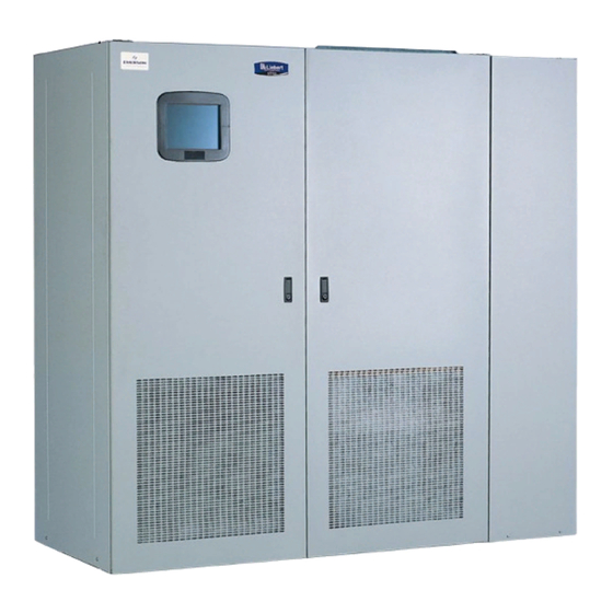
Liebert PDUTM Maintenance Manual (156 pages)
Liebert Corporation OPERATION & MAINTENANCE POWER SUPPLY STS2, PDUTM
Brand:
Liebert
| Category:
Power Supply
| Size: 3.61 MB
Table of Contents
Ontacting Iebert for Upport
2
Table of Contents
3
Save These Instructions
9
Important Safety Instructions
9
1 Unpacking and Inspections
11
External Inspections
11
Unloading and Handling
11
Handling Considerations
12
Unit Preparation
12
Internal Inspections
12
Table 1 Shipping Weights (Typical)
12
2 Location Considerations
13
Recommended Minimum Service Clearances
13
Heat Output
13
Operating Environment
13
Table 2 Heat Output
13
Altitude
14
Figure 1 Recommended Derating for High Altitude Operation
14
Figure 2 Maximum Ambient Temperature for Full Load Operation at Higher Altitudes
14
Table 3 Altitude Conversion-Feet to Meters
14
3 Locating the Sts2/Pdu
15
Anchoring the Unit to the Floor
15
Leveling of the 250A Only STS2/PDU Without Anchoring
15
4 Power and Control Wiring
16
Input and Output Power Connections
16
(Not Available on 250A Units)
17
Figure 3 Typical STS2/PDU, One-Line Diagram
17
Figure 4 Typical STS2/PDU, One-Line Diagram, with Dual Static Switch Output Circuit Breakers
17
Breakers
18
Figure 5 Typical STS2/PDU, One-Line Diagram, with Inline Distribution, Dual Static Switch Output
18
Figure 6 Typical STS2/PDU, One-Line Diagram, with I-Line Distribution, Dual Static Switch Output Circuit
18
Table 4 Input/Output Conduit Plate Specifications
18
System Grounding
19
Control Wiring Connections
19
Remote Source Selection Wiring
19
Table 5 Remote Source Selection Terminal Block
19
Power Supply
20
Table 6 Terminal Block 1 and Terminal Block 2 Wire Connections
20
5 Output Power Wiring
21
Customer Connections
21
Table 7 Distribution Configurations
21
6 Options
22
Programmable Relay Board
22
Input Contact Isolator Board
22
Table 8 Programmable Relay Board Pinout
22
Comms Board
23
Internal Modem
23
Network Interface Card (NIC)
23
Remote Source Selection
24
Key Lockout Switch
24
Static Switch Redundant Output Breaker
24
Inline Panelboards
24
I-Line Panelboards
24
Subfeed Breakers
24
K-Factor Transformers
24
Surge Suppression System
24
7 Installation Drawings
25
Figure 7 Outline Drawing, 250A STS2/PDU
25
Figure 8 Outline Drawing, 250A STS2/PDU with Right Side I-Line Distribution
26
Figure 9 Outline Drawing, 250A STS2/PDU with Right Side Inline Distribution
27
Figure 10 Outline Drawing, 250A STS2/PDU with Left Side I-Line Distribution
28
Figure 11 Outline Drawing, 250A STS2/PDU with Left Side Inline Distribution
29
Figure 12 Outline Drawing,400-600A STS2/PDU with Right Side Inline Distribution
30
Figure 13 Outline Drawing, 400-600A STS2/PDU with Right Side Output Breaker or I-Line Distribution
31
Figure 14 Outline Drawing, 400-600A STS2/PDU with Left Side Inline Distribution
32
Figure 15 Outline Drawing, 400-600A STS2/PDU with Left Side Output Breaker or I-Line Distribution
33
Figure 16 Outline Drawing, 800A STS2/PDU with Right Side Output Breaker or I-Line Distribution
34
Figure 17 Outline Drawing, 800A STS2/PDU with Right Side Inline Distribution
35
Figure 18 Outline Drawing, 800A STS2/PDU with Left Side Output Breaker or I-Line Distribution
36
Figure 19 Outline Drawing, 800A STS2/PDU with Left Side Inline Distribution
37
Figure 20 Outline Drawing, 250A STS2/PDU with Key Lockout Switch Option
38
Figure 21 Outline Drawing, 400-600A STS2/PDU, Inline Distribution, Right Side with Key Lockout
39
Switch Option
39
Figure 22 Outline Drawing, 800A STS2/PDU, Inline Distribution, Right Side with Key Lockout Switch
40
Option
40
Figure 23 Electrical Field Connections, 250A STS2/PDU Input/Output with CB8
41
Figure 24 Electrical Field Connections, 250A STS2/PDU Input with CB3
42
Figure 25 Electrical Field Connections, 250A STS2/PDU Input with CB3 & CB3A
43
Figure 26 Electrical Field Connections, 400-600A STS2/PDU Input with CB3
44
Figure 27 Electrical Field Connections, 400-600A STS2/PDU Input with CB3 and CB3A
45
Figure 28 Electrical Field Connections, 800A STS2/PDU Input with CB3
46
Figure 29 Electrical Field Connections, 800A STS2/PDU Input with CB3 and CB3A
47
Figure 30 Electrical Field Connections, 250A STS2/PDU Output with Inline Panelboards
48
Figure 31 Electrical Field Connections, 400-800A STS2/PDU Output with Inline Panelboards
49
Figure 32 Electrical Field Connections, STS2/PDU Output with I-Line Panelboard
50
Figure 33 Electrical Field Connections, 400-600A STS2/PDU with Right Side Output Breaker
51
Figure 34 Electrical Field Connections, 400-600A STS2/PDU with Left Side Output Breaker
52
Figure 35 Electrical Field Connections, 800A STS2/PDU with Right Side Output Breaker
53
Figure 36 Electrical Field Connections, 8600A STS2/PDU with Left Side Output Breaker
54
Figure 37 Electrical Field Connections, 800A STS2/PDU Interconnect Wiring
55
Figure 38 Electrical Field Connections, 800A STS2/PDU Interconnect Wiring, Breaker Section
56
Figure 39 Electrical Field Connections, 800A STS2/PDU Interconnect Wiring, STS Section
57
Cabinet
58
Figure 40 Electrical Field Connections, 800A STS2/PDU Interconnect Wiring, Left Side Distribution
58
Figure 41 Electrical Field Connections, 800A STS2/PDU Interconnect Wiring, Left Side One-Line
59
Figure 42 Electrical Field Connections, 800A STS2/PDU Interconnect Wiring, Left Side One Line
60
Figure 43 Electrical Field Connections, 800A STS2/PDU Interconnect Wiring, Right Side One Line
61
Figure 44 Electrical Field Connections, 800A STS2/PDU Interconnect Wiring, Right Side One Line
62
Figure 45 Control Wiring, 800A STS2/PDU, Left Side Distribution
63
Figure 46 Control Wiring, 800A STS2/PDU, Right Side Distribution
64
Figure 47 Control Connection Location, 250A STS2/PDU
65
Figure 48 Control Connection Location, 400-800A STS2/PDU
66
Figure 49 Control Location Drawing Conduit Box, Top Entry, 400-600A STS2/PDU
67
Figure 50 Control Wiring for the Programmable Relay Board Option
68
Figure 51 Control Wiring for the Input Contact Isolator Board Option
69
Figure 52 Control Wiring for Comms Board
70
Figure 53 Control Wiring for the Internal Modem Option
71
Figure 54 Control Wiring for the Network Interface Card (NIC) Option
72
Figure 55 Control Wiring for the RS-232 Port
73
Figure 56 Control Wiring for Remote Source Selection Option
74
Figure 57 Color LCD Touch Screen Display
75
Table 10 Output Circuit Breaker Schedule, 250-800A
76
Table 11 Non-Automatic Breaker Schedule, 250-800A
76
Table 9 Input Circuit Breaker Schedule, 250-800A
76
8 Ists2/Pdu O
77
Ntroduction to Sts2/Pdu Operations
77
System Description
77
Redundancy
77
Reliability and Agency Requirements
78
Factory Backup and Service Assistance
78
Modes of Operation
78
Normal (Preferred Source)
78
Transfer
79
Transfer Inhibit
79
Bypass
79
Operator Controls
79
Figure 58 STS2/PDU Touch Screen Display
79
9 Theory of Operation
80
General Description
80
Static Transfer Switch 2 Power Distribution Unit
80
Source Transfer
80
Automatic Transfer/Retransfer
80
Emergency Transfer
81
Load Current Transfer Inhibit
81
SCR Failure
81
On/Off Sequence
81
Detailed Component Description
81
Controls
81
Circuit Breakers and Non-Automatic Circuit Breakers
82
Scrs
82
Logic Modules
82
Audible Alarm
82
Port
82
RS-232 Port
82
10 Operating Instructions
83
Normal System Turn-On
83
Figure 59 STS2/PDU Touch Screen Display
83
Manual Transfer / Preferred Source Selection
84
Enabling Remote Source Selection
85
Figure 60 Source Transfer Screen
85
Maintenance Bypass
86
Figure 61 Gate Board Viewing Slot Locations
86
Bypass Procedures for Source 1
87
Bypass Procedures for Source 2
88
Normal System Shutdown
88
Shutdown in Static Transfer Switch Mode
88
Shutdown in Maintenance Bypass Mode
89
11 Larms and Faults
90
A Larms and F Aults
90
Event Mask
90
Event and History Logs
91
Event Log
91
History Log
92
Alarm Notes
92
List of Messages
92
Table 12 Event Messages
93
12 Communication
95
Ommunication Nterfaces
95
C Ommunication I Nterfaces
95
Using the RS-232 Port
96
Connecting and Using a Terminal
96
Table 13 Terminal Commands
96
Configuring the STS2/PDU Via the Terminal
97
Table 14 Value Types
98
Table 15 Group Settings and Values
99
Setting Bitpacked Options with the Terminal
100
Table 16 Binary-Hexadecimal Conversions
101
Setting Event Masks with the Terminal
102
13 Touch Screen Display
104
Display Overview
104
Figure 62 STS2/PDU Touch Screen Display
104
Menu Overview
105
Figure 63 Menus
105
Figure 64 Keyboard and Keypad Displays
105
Figure 65 Key Lockout Switch
106
Security
106
MIMIC Display
107
Event Controls
107
Event Display
107
Menu Bar
107
Configuration Menu
107
Figure 66 Event Mask Dialog Box
108
Figure 67 User Settings Dialog Box
109
Figure 68 Source Setpoints
110
Table 17 Setpoint Parameters
110
Figure 69 PDU Setpoints
112
Table 18 PDU Setpoints
112
Figure 70 Comm Options Dialog Box
113
Figure 71 Modem Dialog Box
114
Figure 72 Input Contact Isolator Dialog Box
116
Table 19 Standard Settings for Programmable Relays
117
Figure 73 Programmable Relay Board Dialog Box
118
Figure 74 System Options
119
Figure 75 PDU Options Button
120
Figure 76 Event Log
121
Figure 77 History Log
121
Logs
121
Bypass Procedure
122
Help
122
Logo
122
Source Transfers
122
Startup Procedure
122
Cleaning the LCD Touch Screen
122
14 Specifications
123
System Configuration
123
Frequency
123
Input Voltage
123
Output Voltage
123
System Current Ratings
123
Grounding
123
Table 20 Input Voltage
123
Table 21 Output Voltage
123
Table 22 System Current Ratings
123
Electrical Requirements
124
Surge Suppression
124
Response Time
124
Environmental Requirements
124
System Components
124
Table 23 Electrical Requirements
124
Table 23 Table
124
Table 24 Unit Short Circuit Withstand Capability
124
Caster and Leveling - 250A Only
125
Cooling
125
Frame and Enclosure
125
Table 25 Frame Sizes
125
Access
126
Cable Entrance
126
Circuit Breakers
126
Color Graphical Display
126
Doors
126
Port
127
Table 26 MTA Plug Pinout
127
Table 27 DB9 Pinout
127
Terminal Port Connections
127
Fuseless Design
128
Interface Parameters
128
Maintenance Bypass
128
Options
128
Table 28 RS-232 Settings
128
15 Event Message Help Text
129
16 Maintenance
152
Proper Tightening of Nuts and Bolts
152
Testing the STS2/PDU
152
Changing the Air Filter
152
Table 29 Torque Tightening
152
Table 30 Branch Circuit Breakers
152
17 Customer
153
Ustomer Ettings
153
Programmable Relay Board Settings
153
Table 31 Programmable Relay Board Settings Record
153
Input Contact Isolator Settings
154
Table 32 Input Contact Isolator Settings Record
154
Advertisement
Advertisement
Related Products
Liebert PowerSure PSA
Liebert PowerSure Personal
Liebert PFH066A-L
Liebert Challenger Plus CP32A D
Liebert PEX+ Series
Liebert Challenger Plus CP46H U
Liebert Challenger Plus CP40H U
Liebert Challenger Plus CP46D U
Liebert Challenger Plus CP28D
Liebert Challenger Plus CP28F U
Liebert Categories
UPS
Air Conditioner
Power Supply
Surge Protector
Chiller
More Liebert Manuals
Login
Sign In
OR
Sign in with Facebook
Sign in with Google
Upload manual
Upload from disk
Upload from URL