Table of Contents
Advertisement
Quick Links
Pellet-Fired
Fireplace Insert
Save These Instructions
For Future Reference
P/N 900139-00, Rev. A, 05/2015
C
US
Report No. 14-188
INSTALLATION AND OPERATION MANUAL
P900139-00
A French manual is available upon request. Order P/N 900140-00.
Ce manuel d'installation est disponible en francais, simplement en faire la demande. Numéro de la pièce
900140-00.
This appliance must be properly installed and operated in order to prevent the possibility
of a house fire. Please read this entire manual before installation and use of this pel-
let fuel-burning room heater. Failure to follow these instructions could result in
property damage, bodily injury or even death. Contact your local building or
• Hot! Do not touch! The glass and surfaces of this appliance will be
hot during operation and will retain heat for a while after shutting off
the appliance. Severe burns may result.
• Carefully supervise children in the same room as appliance.
• IHP pellet-burning appliances are designed for use as a supplemental
heater. They are not intended for continuous use as a primary heat
source.
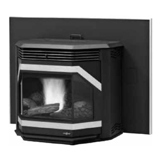
Model Winslow™ (PI40)
fire officials to obtain a permit and information on any installation require-
ments and inspection requirements in your area.
WARNING
Pellet Insert
Advertisement
Table of Contents

Related Manuals for IronStrike Winslow PI40


Summary of Contents for IronStrike Winslow PI40
- Page 1 INSTALLATION AND OPERATION MANUAL Pellet-Fired Fireplace Insert Save These Instructions For Future Reference P/N 900139-00, Rev. A, 05/2015 Pellet Insert P900139-00 Model Winslow™ (PI40) A French manual is available upon request. Order P/N 900140-00. Ce manuel d’installation est disponible en francais, simplement en faire la demande. Numéro de la pièce 900140-00.
-
Page 2: Important Safety Warnings
11. APPROVED FUEL: This appliance is designed specifically for IMPORTANT SAFETY AND WARNING use only with pelletized wood pellets or a mixture of up to INFORMATION 50% corn mixed with a minimum of 50% pelletized wood pel- lets. This mixture of wood pellets and corn should be evenly pre-mixed before being placed in the units hopper. -
Page 3: Table Of Contents
CONGRATULATIONS! Pellet Fuel ..............Page 21 Corn Fuel ..............Page 21 When you purchased your new pellet fireplace insert, you Cautions ..............Page 21 joined the ranks of thousands of individuals whose answer to Cleaning and Maintenance ..........Page 22-25 their home heating needs reflects their concern for aesthetics, efficiency and our environment. -
Page 4: Planning Your Installation
PLANNING YOUR INSTALLATION WARNING Questions To Ask Local Building Official Electrical grounding instructions: This appliance is A correct installation is critical and imperative for reducing fire hazards and equipped with a three-prong (grounding) plug for perilous conditions that can arise when wood pellet burning appliances your protection against shock hazard and should are improperly installed. -
Page 5: Selecting A Location
NEGATIVE PRESSURE WARNING SELECTING A LOCATION This appliance is not designed to be operated in a negative pressure envi- The design of your home and where you place your stove will determine ronment. In very airtight homes with large kitchen exhaust fans, furnace its value as a source of heat. -
Page 6: Features And Specifications
Appearance Options FEATURES AND SPECIFICATIONS The Winslow PI40 insert can be ordered with the following door trims, grills, surround (flange) assemblies, log set and brick panel options : Installation Options • Residential Door Trim Kits Grill Kits • Vented vertical and horizontal (see venting instructions) - Page 7 Wood pellets manufactured to the pellet fuels institute (P.F.I.) certification FUEL standard are available in two grades, Standard and Premium. The primary difference between the two is the ash content of the pellets. CAUTION The P.F.I. specification for standard grade and premium grade residential and commercial pellet fuel is as follows: The use of unapproved, dirty, wet and / or high salt •...
-
Page 8: Insert Dimensions
INSERT DIMENSIONS 2-1/2” Minimum Screen Pocket is Needed for the Control Board (not applicable if P/N H7232 ZC Surround Kit is used*) Front View 26-1/4” 23” (584mm) 15-1/2” 15” (667mm) (394mm) (381mm) Minimum 36” (914mm) Minimum* Control Board Side 23-3/8” Surround (594mm) Panel... -
Page 9: Clearances To Combustibles
HEARTH PROTECTION CLEARANCES TO COMBUSTIBLES The floor protector must be a non-combustible material extending IMPORTANT beneath the insert from the surround panels forward and to the front and sides as shown in Figure 7. Important, if anything other than a •... -
Page 10: Installation
1. Do not terminate the vent in any enclosed or semi-enclosed areas such as a carport, garage, attic, crawlspace, narrow walkway, closely The Winslow PI40 insert is shipped with the control board wrapped and fenced area, under a sundeck or porch, or any location that can build placed behind the firebox. -
Page 11: Vent Termination Locations
Vent Termination Locations Air Supply Inlet Vent Terminal Vertical Terminal Area Where Terminal Is Not Permitted USA - 1' Min. 24” CANADA - 3' Min. (610mm) Vertical Terminal (From Eave) USA - 1' Min. 24” CANADA - 3' Min. (610mm) Fixed Closed NOTE: Vent requirements are in accordance with NFPA 211 and CAN/... -
Page 12: Insert Leveling
The recommended pipe installation is running the pellet pipe from the insert all the way to the top of the chimney. However, *The block off panel should be the pipe may terminate inside the chimney above the damper if air tight to ensure smoke does the chimney is sealed below the pellet pipe termination with a not enter the house and to help establish chimney draft when the... -
Page 13: Mobile Home Installations
• Installation should be in accordance with the Manufactured Home and Safety Standard (HUD), CFR 3280, Part 24. 36" FIREPLACE OPENING • Connecting the Winslow PI40 insert to outside combustion air is required in manufactured home installations and when 18"... -
Page 14: Outside Air Installations
Outside Air Installations Door Trim Installation Instructions (ref. form # 775274M) Connecting the Winslow PI40 insert to outside combustion air is required Parts List (A) in manufactured home installations and when required by local building codes. The fireplace insert’s air intake will accept 2” ID pipe to accom- (2) Trim Pieces (Black, Gold, Nickel, Brushed Nickel or Black Nickel) modate outside air installations. - Page 15 4. Place one washer on each stud. Using a 3/8” nut driver, snug up the nuts on each piece of trim. Do not finish tightening the nuts yet. See Figure 19. 5. There should be approximately a 7/8” (22 mm) gap between the top edge of the upper door trim and the top edge of the front door and 9/16”...
-
Page 16: Door Grill Installation Instructions
Door Grill Installation Instructions 3. Rotate the grill back to the horizontal position, then using 1/8” allen (ref. form # 775273M) wrench or t-handle wrench, re-install the four button head screws through the two holes at each end of the grill and into the stove body. Parts Needed See Figures 23 and 24. - Page 17 Brick Panel Installation 2. Remove all pellets and ash from the firebox to ensure a proper fit for the brick panel. Option: Part #79030 3. Insert the brick panel, top first, as shown in Figure 27. The two cut Kit Contents out corners should be at the bottom.
- Page 18 6. Replace the Burn-Pot and check that it is firmly in place (if you can 5. Screw in the four tap tights, included with this kit, using a 5/32 allen wrench. rotate the Burn-Pot it is not installed correctly). If present, install the optional log set according to the log set installation instructions (included with your log set).
- Page 19 Log Set Installation Instructions (ref. form # 775275M) Kit Contents (refer to Figure 30) 1 ea. Left Log (A) 1 ea. Right Log (B) 1 ea. Front Log (C) 2 ea. Log Support Brackets (D) 1 ea. Instruction Sheet bend lines Cat.
-
Page 20: Operation
Lighting OPERATION 1. Turn the heat selector knob (see Figure 34) to the heat level desired - 1 Control Board through high - and the ready light will turn green. 2. Push the start button and the ignite and feeding lights will come on and the lighting sequence will begin. -
Page 21: Shut Down
Corn Fuel down cycle. Shelled corn can be burned in the Winslow PI40 insert when it is mixed Power Outage - If the insert loses electrical power for less than 10 seconds with wood pellet fuel (see Fuel Specifications on Page 7). The mixture it will continue to operate. -
Page 22: Cleaning And Maintenance
CLEANING AND MAINTENANCE High Side Of Burn-Pot Towards Front Of Insert IMPORTANT CAUTIONS: • UNPLUG POWER CORD AND ENSURE APPLIANCE IS COLD BEFORE PERFORMING ANY MAINTENANCE WORK. • Some brands of pellets produce more ash and clinkers than others. Therefore the frequency of performing the following cleaning procedures depends to a great degree on the quality of the pellets burned. -
Page 23: Cleaning Combustion Blower
Flue Passageways Cleaning Procedure (Recommended Frequency of Yearly*) Right Side View 1. Open both the right and left side door to locate side flue passageways (see Figure 36A). 2. There is one upper and one lower, 1” x 2”, flue passageways on both the left and right sides (see Figures 36A, 36B and 36C). -
Page 24: Removing Ash From The Firebox
Slide to the side to remove. Figure 37 Figure 39 Rotate Proof of Fire Switch Latch Handle (Recommended Frequency of 1 year or after every 100 bags of fuel used*) This switch needs to be removed and cleaned after every 100 bags of fuel burned. -
Page 25: Front Door Opening And Removal
Hopper Extension Hopper Lid Front Door Figure 40 Figure 41 Front Door Opening and Removal CAUTION: Do not open the front door when the insert is hot. To remove the door, swing the left and right side doors A open. Pull the front door handle B to the front and swing the front door open. -
Page 26: Component Location And Functions
Vacuum Switch - The Winslow PI40 insert has a vacuum switch located behind the left door, fastened to the base (see A in Figure 45). If there is a leak in the firebox created by the front door being ajar or a blocked flue, the vacuum switch will sense it and cause the insert to go into a shutdown mode. -
Page 27: Draft Adjuster
Draft Adjuster - Adjustment Procedure After the draft adjuster is adjusted, re-evaluate the appearance of the flame. It may be necessary to continue adjusting it in increments until proper combustion is achieved (the flame should become a brighter The Winslow™ PI40 insert has a draft adjuster located at the right side yellow and begin to “dance”). -
Page 28: Diagnostic Codes
DIAGNOSTIC CODES If the insert operates abnormally, the ready light on the control board will signal the nature of the abnormal operation. The following is a list of pos- sible signals or codes: Ready light is constant red Ignition Failure Ready light flashes red 1 short and 1 long blink Vacuum Switch Open Ready light flashes red 2 short blinks... - Page 29 Over Temperature Snap Switch Shuts Insert Down - Code - Ready light flashes red 2 long blinks Possible Problem Solution Convection blower not running Blower dirty, blower snap switch bad, or blower broken Flue passageways or vent restricted Clean passageways or vent pipe (see Pages 22 and 23) Snap switch* defective Replace the snap switch* * NOTE: The snap switch has a reset button that must be pushed before insert will function (see Page 26).
-
Page 30: Replacement Parts
REPLACEMENT PARTS - WINSLOW™ PI40 Contact an IHP dealer to obtain any of these parts. Never use substitute materials. Use of non-approved parts can result in poor performance and safety hazards. Winslow™ PI40 insert 79040 Door w/glass (No Trim) H6021 Flue Clean Out Box Cat. -
Page 31: Accessories
ACCESSORIES Door Trim (required - sold separately) (ref. Form # 775274M) Item No. Cat. No. Model Description 79038 P40DT-B Black Surround Panel Kits (required - sold separately) (ref. Form # 775279M) 79034 P40DT-G Gold Cat. No. Model Description 79037 P40DT-N Nickel 79004 PI40-FPK2941... - Page 32 Common Accessories Item Cat. No. Model Description ------ 79003 PI40FS Front Support 41-48” Width/0-8” Height (ref. Form # 775296M) H5142 P40LOG Log Set (ref. Form # 775275M) 79030 P40BRICK Standard Brick Panel (ref. Form # 775276M) H8860 RC-S-1 Remote, Two Button, Timer, On/Off or Timer Mode H8861 RCL-S-STAT...
-
Page 33: Heat Kit Instructions
Heat Kit Instructions (ref. form # 506033-01) Kit Contents (Refer to Figure 48) 1 ea. 2” lower trim piece (A) 1 ea. 1” Insulation Board (B) 2 ea. 1/2” x 10-24” screws (C) 1 ea. Instruction Sheet Pellet Heat Kit Cat. -
Page 34: Pellet Insert Zc Kit Assembly Instructions
Pellet Insert ZC Kit Assembly NOTE: Top or rear vent? If you will be venting out the top then you will install the block off plate (F in Figure 53) onto the lower back panel (A) (ref. form # 775277M) in the spot that is marked “z”... - Page 35 Bottom 2 holes on each side Figure 56 Figure 58 4. Install the top panel (D). Place the top panel (D) on top of the pe- rimeter panels (A, B, and C). Using only the three holes along the left and right side of the top panel (D), screw panel (D) onto the side panels (A and B).
- Page 36 7. Remove the 3 screws located across the top of the pellet hopper (see 9. Install the access panel (E) by screwing it onto the right side panel Figure 60). (C), using four of the sheet metal screws provided. Figure 62 Figure 60 10.
-
Page 37: Zc Framing Dimensions For
ZC Framing Dimensions for Combustible / Floor Top View Exhaust 8-1/4” (210mm) Front 9-1/8” (232mm) 39” (991mm) Front View Exhaust Intake Power Cord 6-3/4” 4” (172mm) 3-1/2” (102mm) (89mm) 10-3/8” (264mm) 19-1/2” (495mm) 25-1/2” (648mm) Side View Outside Air Intake 29-1/2”... -
Page 38: Zc Framing Dimensions For Non-Combustible Hearth /Floor
ZC Framing Dimensions for Non-Combustible Hearth / Floor Top View Exhaust 8-1/4” (210mm) Front 9-1/8” (232mm) 39” (991mm) Front View Exhaust Intake A/C Power Cord 4-3/4” (121mm) 3”(76mm) 2-1/2”(64mm) 10-3/8” (264mm) 19-1/2” (495mm) 25-1/2” (648mm) Side View Outside Air Intake 28”... -
Page 39: Warranty
THE WARRANTY Innovative Hearth Products ("IHP") Limited Lifetime Warranty warrants your IronStrike™ brand pellet fueled stove or insert ("Product") to be free from defects in materials and workmanship at the time of manufacture. The Product body, heat exchange tubes and ceramic glass carry the Limited Lifetime Warranty. Ceramic glass carries the Limited Lifetime Warranty against thermal breakage only. -
Page 40: Product Reference Information
1508 Elm Hill Pike, Suite 108 See Page 30 for a complete replacement parts list. Use only parts sup- Nashville, TN 37210 plied from the manufacturer. visit us at www.IronStrike.us.com Model Number _____________________________________________________ Serial Number _____________________________________________________ Installation Date ____________________________________________________ Dealer’s Name _____________________________________________________ Dealer’s Phone Number ______________________________________________...
Need help?
Do you have a question about the Winslow PI40 and is the answer not in the manual?
Questions and answers