Table of Contents
Advertisement
INSTALLATION AND OPERATION MANUAL
EPA Certified
Wood-Burning
Fireplace Inserts
Save These Instructions
For Future Reference
P/N 900123-00, Rev. A, 04/2014
P900123-00
A French manual is available upon request. Order P/N 900122-00.
Ce manuel d'installation est disponible en francais, simplement en faire la demande. Numéro de
la pièce 900122-00.
101539175PRT-001
• Hot! Do not touch! The glass and surfaces of this appliance will
be hot during operation and will retain heat for a while after
shutting off the appliance. Severe burns may result.
• Carefully supervise children in the same room as appliance.
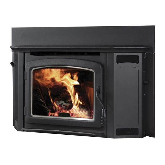
Wood-Burning Fireplace Inserts
Model Montlake™ ML230 and ML300
This appliance must be properly installed and operated in order to prevent the
possibility of a house fire. Please read this entire installation and operation
manual before installing and using your wood fireplace insert. Failure
to follow these instructions could result in property damage, bodily
injury or even death. Contact your local building or fire officials
to obtain a permit and information on any installation re-
quirements and inspection requirements in your area.
WARNING
Montlake™ 230 and 300
With Innovative Thermal Fin Technology (TFT™)
Advertisement
Table of Contents


Need help?
Do you have a question about the Montlake 230 and is the answer not in the manual?
Questions and answers