
Related Manuals for PowerWalker VFI 20000-40000TAP 3/3 BE


Summary of Contents for PowerWalker VFI 20000-40000TAP 3/3 BE
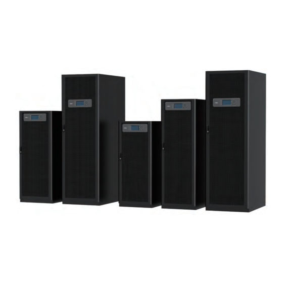
- Page 1 PowerWalker VFI 3/3 Series VFI 20000-40000TAP 3/3 BE/BI VFI 60000-80000TAP 3/3 BX 380/400/415V 50/60Hz (3-phase input/output) User Guide...
- Page 3 IMPORTANT SAFETY INSTRUCTIONS SAVE THESE INSTRUCTIONS This manual contains important instructions that you should follow during installation and maintenance of the UPS and batteries. Please read all instructions before operating the equipment and save this manual for future reference. CONSIGNES DE SÉCURITÉ IMPORTANTES CONSERVER CES INSTRUCTIONS Ce manuel comporte des instructions importantes que vous êtes invité...
-
Page 5: Table Of Contents
Table of Contents InTroduCTIon . . . . . . . . . . . . . . . . . . . . . . . . . . . . . . . . . . . . . . . . . . . . . . . . . . . . . . . . . . . . . . . . . . . . . . . . . . . . . . . . . . . . . . UPS Standard Features . - Page 6 SeCTIon 2—oPeraTIon underSTandIng uPS oPeraTIon . . . . . . . . . . . . . . . . . . . . . . . . . . . . . . . . . . . . . . . . . . . . . . . . . . . . . . . . . . . . . . . . . . . . UPS System Overview .
- Page 7 CommunICaTIon . . . . . . . . . . . . . . . . . . . . . . . . . . . . . . . . . . . . . . . . . . . . . . . . . . . . . . . . . . . . . . . . . . . . . . . . . . . . . . . . . . . 7 .1 Mini-Slot Cards .
- Page 8 This page intentionally left blank.
- Page 9 PowerWalker VFI 3/3 series UPS (VFI 20000-80000TAP) ....... . .
- Page 10 This page intentionally left blank.
- Page 11 List of Tables Table 3-1. UPS Cabinet Weights ..............Table 3-2.
- Page 12 This page intentionally left blank. viii...
-
Page 13: Introduction
AC power to protect the customer's load from power failures. The PowerWalker VFI 3/3 Series VFI 20000-80000TAP 3/3 BE/BI online power protection system is used to prevent loss of valuable electronic information, minimise equipment downtime, and minimise the adverse effect on production equipment due to unexpected power problems. -
Page 14: Ups Standard Features
The PowerWalker VFI 3/3 Series UPS offers a High-Efficiency (HE) normal mode with double-conversion on demand that allows the UPS to operate in standby bypass mode. This mode allows the PowerWalker VFI 3/3 Series UPS to achieve 98% efficiency while still protecting the load. See Chapter 6, “UPS Operating Instructions,”... -
Page 15: Options And Accessories
Modbus. See Chapter 7 , “Communication, “ for additional information on monitoring and communication features. 1.2.4 Dual Input Dual feed models are available for PowerWalker VFI 3/3 Series UPS. Connectors on dual feed models provide a separated bypass input to UPS. -
Page 16: Battery System
Remote Emergency Power-off (REPO) control or Mini-Slot communication cards. Using This Manual This manual describes how to install and operate the PowerWalker VFI 3/3 Series VFI 20000-80000TAP 3/3 BE/BI/BX. Read and understand the procedures described in this manual to ensure trouble-free installation and operation. -
Page 17: Symbols, Controls, And Indicators
Symbols, Controls, and Indicators The following are examples of symbols used on the UPS or accessories to alert you to important information: RISK OF ELECTRIC SHOCK - Observe the warning associated with the risk of electric shock symbol. CAUTION: REFER TO OPERATOR'S MANUAL - Refer to your operator's manual for additional information, such as important operating and maintenance instructions. - Page 18 This page intentionally left blank.
-
Page 19: Safety Warnings
Chapter 2 Safety Warnings IMPORTANT SAFETY INSTRUCTIONS SAVE THESE INSTRUCTIONS This manual contains important instructions that should be followed during installation and maintenance of the UPS and batteries. Read all instructions before operating the equipment and save this manual for future reference. The UPS is designed for industrial or computer room applications, and contains safety shields behind the door and front panels. - Page 20 • See installation instructions before connecting to the supply. • Risk of explosion if battery is replaced by an incorrect type. Dispose of used batteries according to the instructions. • Replace batteries with the same number and type of batteries as originally installed with the UPS.
-
Page 21: Section 1-Installation
Section 1 Installation... -
Page 23: Ups Installation Plan And Unpacking
Chapter 3 UPS Installation Plan and Unpacking Use the following basic sequence of steps to install the UPS: Create an installation plan for the UPS system (Chapter 3). Prepare your site for the UPS system (Chapter 3). Inspect and unpack the UPS cabinet (Chapter 3). Unload and install the UPS cabinet, and wire the system (Chapter 4). -
Page 24: Table 3-1. Ups Cabinet Weights
Failure to follow guidelines may void your warranty. The UPS equipment operating environment must meet the weight requirements shown in Table 3-1 and the size requirements shown in Figure 3-1 through Figure 3-5. Dimensions are in millimetres (inches). Table 3-1. UPS Cabinet Weights Weight kg (lb.) Model... -
Page 25: Table 3-2. Ups Cabinet Clearances
• Ambient Temperature Range: 0–40°C (32–104°F) • Recommended Operating Range: 20–25°C (68–77°F) • Maximum Relative Humidity: 95%, noncondensing Table 3-3. Required Clearance Required Clearance for paralleled adjacent UPS or UPS and adjacent PDU VFI 20000-40000TAP 3/3 BE/BI VFI 60000-80000TAP 3/3 BX ambient L1(mm) L2(mm) -
Page 26: Table 3-4. Air Conditioning Or Ventilation Requirements During Full Load Operation
CAUTION If battery systems are located in the same room as the UPS, the battery manufacturer's environmental requirements should be followed if they are more stringent than the UPS requirements. Operating temperatures above the recommended range will result in decreased battery life and performance, and may reduce or void the battery warranty. - Page 27 706 (27.8) 500 (19.69) FRONT VIEW RIGHT VIEW REAR VIEW VFI 20000TAP 3/3 BI / VFI 20000TAP 3/3 BE Figure 3-1. UPS Cabinet Dimensions (VFI 20000 TAP 3/3 BE/BI Front and Right Side Views) Dimensions are in millimetres [inches]...
- Page 28 500 (19.69) 500 (19.69) 706 (27.8) 706 (27.8) RIGHT VIEW REAR VIEW FRONT VIEW VFI 30000TAP 3/3 BI / VFI 30000TAP 3/3 BE Figure 3-2. UPS Cabinet Dimensions (VFI 30000TAP 3/3 BE/BI Front and Right Side Views) Dimensions are in millimetres [inches]...
- Page 29 500 (19.69) 706 (27.8) FRONT VIEW RIGHT VIEW REAR VIEW VFI 40000TAP 3/3 BI / VFI 40000TAP 3/3 BE Figure 3-3. UPS Cabinet Dimensions (VFI 40000TAP 3/3 BE/BIFront and Right Side Views) Dimensions are in millimetres [inches]...
- Page 30 VFI 60000TAP 3/3 BX 600 (23.62) 796 (31.34) REAR VIEW FRONT VIEW RIGHT VIEW VFI 80000TAP 3/3 BX 600 (23.62) 796 (31.34) REAR VIEW FRONT VIEW RIGHT VIEW Figure 3-4. UPS Cabinet Dimensions (VFI 60000-80000TAP 3/3 BX Front and Right Side Views) Dimensions are in millimetres [inches]...
- Page 31 500 (19.69) FRONT FRONT TOP VIEW BOTTOM VIEW 500 (19.69) VFI 20000TAP 3/3 BI / VFI 20000TAP 3/3 BE / VFI 40000TAP 3/3 BI / VFI 40000TAP 3/3 BE FRONT FRONT 600 (23.62) TOP VIEW BOTTOM VIEW VFI 60000TAP 3/3 BX / VFI 80000TAP 3/3 BX 600 (23.62) Figure 3-5.
-
Page 32: Figure 3-6. Ups Cabinet Centre Of Gravity (Vfi 20000Tap 3/3 Be/Bi)
353 (13.9) 250 (9.84) 500 (19.69) 706 (27.8) FRONT VIEW RIGHT VIEW VFI 20000TAP 3/3 BI / VFI 20000TAP 3/3 BE Figure 3-6. UPS Cabinet Centre of Gravity (VFI 20000 TAP 3/3 BE/BI) Dimensions are in millimetres [inches] 3-10... -
Page 33: Figure 3-7. Ups Cabinet Centre Of Gravity (Vfi 30000Tap 3/3 Be/Bi)
250 (9.84) 353 (13.9) 500 (19.69) 706 (27.8) FRONT VIEW RIGHT VIEW VFI 30000TAP 3/3 BI / VFI 30000TAP 3/3 BE Figure 3-7. UPS Cabinet Centre of Gravity (VFI 30000TAP 3/3 BE/BI) Dimensions are in millimetres [inches] 3-11... -
Page 34: Figure 3-8. Ups Cabinet Centre Of Gravity (Vfi 40000Tap 3/3 Be/Bi)
250 (9.84) 353 (13.9) 500 (19.69) 706 (27.8) FRONT VIEW RIGHT VIEW VFI 40000TAP 3/3 BI / VFI 40000TAP 3/3 BE Figure 3-8. UPS Cabinet Centre of Gravity (VFI 40000TAP 3/3 BE/BI) Dimensions are in millimetres [inches] 3-12... -
Page 35: Figure 3-9. Ups Cabinet Centre Of Gravity (Vfi 60000Tap 3/3 Bx)
300 (11.81) 300 (11.81) 600 (23.62) 600 (23.62) 796 (31.34) 796 (31.34) FRONT VIEW RIGHT VIEW VFI 60000TAP 3/3 BX Figure 3-9. UPS Cabinet Centre of Gravity (VFI 60000TAP 3/3 BX) Dimensions are in millimetres [inches] 3-13... -
Page 36: Figure 3-10. Ups Cabinet Centre Of Gravity (Vfi 80000Tap 3/3 Bx)
300 (11.81) 300 (11.81) 600 (23.62) 796 (31.34) FRONT VIEW RIGHT VIEW VFI 80000TAP 3/3 BX Figure 3-10. UPS Cabinet Centre of Gravity (VFI 80000TAP 3/3 BX) Dimensions are in millimetres [inches] 3-14... -
Page 37: Ups System Power Wiring Preparation
3.2.2 UPS System Power Wiring Preparation The UPS system installation must meet the following guidelines: • The system must be installed on a level floor suitable for computer or electronic equipment. • The system must be installed in a temperature and humidity controlled indoor area free of conductive contaminants. - Page 38 • The bypass feed into this equipment uses four wires (three line conductors and neutral conductor), plus grounding conductor (protective earthing conductor) . The rectifier feed into this equipment uses four wires (three line conductors and neutral conductor), plus grounding conductor (protective earthing conductor). The phases must be symmetrical about ground (from a Wye/Star source) for proper equipment operation.
-
Page 39: Table 3-5. Input /Output Ratings And External Wiring Requirements For The Vfi 20000-80000Tap
Table 3-5. Input / Output Ratings and External Wiring Requirements for the VFI 20000-80000TAP Units Rating 50/60 Hz cross-sections Basic Unit Rating Refer the IEC 62040-1 13.5 Input and Output Voltage 400/400 400/400 400/400 400/400 400/400 400/400 Volts A: AC Input to UPS Rectifier (0.99 Minimum PF) Amps Full load current plus battery recharge current (3) Phases... -
Page 40: Table 3-6. Ups External Power Cable Terminations For The Vfi 20000-80000Tap
Table 3-6. UPS External Power Cable Terminations for the VFI 20000-80000TAP Tightening Tightening Terminal Torque Torque Function Terminal Function Bus landing Nm (lb in) Screw Size and Type Bus landing Nm (lb in) Screw Size and Type VFI 20000-30000TAP 3/3 BE/BI VFI 40000 3/3 BE/BI VFI 60000-80000TAP 3/3 BX AC Input... -
Page 41: Table 3-7. Recommended Input Circuit Breaker Ratings
Table 3-7. Recommended Input Circuit Breaker Ratings Circuit Breaker Rating UPS Model Load Derating 400V 80% Derated VFI 20000TAP >1277A 100% Rating 80% Derated VFI 30000TAP >2497A 100%Rating 80% Derated VFI 40000TAP >5108A 100% Rating 80% Derated 115A VFI 60000TAP >9988A 100% Rating 80% Derated... -
Page 42: Table 3-9. Recommended Dc Input Circuit Breaker Rating
There is no DC disconnect device within the UPS. A battery disconnect switch is recommended, And may be required by local codes when batteries are remotely located. The battery disconnect switch should be installed between the battery and the UPS External DC input overcurrent protection and disconnect switch for the remote battery location is to be provided by the user. -
Page 43: Ups System Interface Wiring Preparation
3.2.3 UPS System Interface Wiring Preparation Control wiring for features and options should be connected at the customer interface terminal blocks located inside the UPS. WARNING Do not directly connect contactor contacts to the mains related circuits. Reinforced insulation is required before connecting to the mains. -
Page 44: Inspecting And Unpacking The Ups Cabinets
Inspecting and Unpacking the UPS Cabinets The cabinet is shipped bolted to a wooden pallet and protected with an outer wood container. WARNING The UPS cabinet is heavy (see Table 3-1). If unpacking and unloading instructions are not closely followed, the cabinet may tip and cause serious injury. Carefully inspect the outer packaging for evidence of damage during transit. -
Page 45: Figure 3-12. Ups Cabinet As Shipped On Pallet
NOTE While waiting for installation, protect the unpacked cabinet from moisture, dust, and other harmful contaminants. Failure to store and protect the UPS properly may void your warranty. Figure 3-12. UPS Cabinet as Shipped on Pallet 3-23... - Page 46 This page intentionally left blank. 3-24...
-
Page 47: Ups System Installation
Chapter 4 UPS System Installation Preliminary Installation Information WARNING Installation should be performed only by qualified personnel. See installation instructions before connecting to the supply. Refer to the following while installing the UPS system: • Chapter 3 for cabinet dimensions, equipment weight, wiring and terminal data, and installation notes. ±... -
Page 48: Figure 4-1. Removing The Shipping Bracket
Front Door Shipping Bracket Bolts Pallet Shipping Bracket Figure 4-1. Removing the Shipping Bracket WARNING Do not stand directly in front of the pallet while unloading the cabinet. If unloading instructions are not closely followed, the cabinet may cause serious injury. Slowly roll the cabinet toward the front of the pallet. -
Page 49: Figure 4-2. Attaching The Ramp To The Pallet
UPS Cabinet Pallet Ramp Figure 4-2. Attaching the Ramp to the Pallet UPS System Installation Figure 4-3. Rolling the Cabinet Down the Ramp Figure 4-4. Rolling the Cabinet Down the Ramp... -
Page 50: External Battery Cabinet Installation
External Battery Cabinet Installation Before connecting the external battery, please read the notice and warning label on the battery cabinet. WARNING • In the event of malfunction, the battery cabinet chassis or battery cabinet frames may become live! • Special care should be taken when working with the battery cabinet associated with the equipment. -
Page 51: External Power Wiring Installation
External Power Wiring Installation Without accessory cabinets, conduit and wiring enter from the bottom of the UPS NOTE conduit landing plate. With accessory cabinets, wiring can be installed between the UPS and accessory cabinets by using conduit or by routing wiring through the power terminal cover base wiring channels. -
Page 52: Figure 4-4. Power Terminal Locations Vfi 20000-40000Tap 3/3 Be/Bi
AC Output to Critical Load Phase B (L2) Phase C (L3) Phase A (L1) REAR VIEW VFI 20000-40000TAP 3/3 BE/BI Note: Connection terminals for these models are accessible from the rear of the UPS cabinet. Figure 4-4. Power Terminal Locations VFI 20000-40000TAP 3/3 BE/BI/... -
Page 53: Figure 4-5. Power Terminal Locations Vfi 60000-80000Tap 3/3 Bx
External Battery - Neutral (N) Phase C (L3) AC Input to Phase B (L2) UPS Bypass External Battery + Phase A (L1) Ground Terminals RIGHT VIEW Phase A (L1) Phase C (L3) AC Input to AC Output to Phase B (L2) Phase B (L2) Critical Load UPS Rectifier... -
Page 54: Installing Interface Connections
(See Figure 4-7 for detail) FRONT MIDDLE Interface Terminals COVER PLATE (See Figure 4-7 for detail) Interface Terminals (See Figure 4-7 for detail) FRONT MIDDLE COVER PLATE FRONT VIEW FRONT VIEW VFI 20000-40000TAP 3/3 BE/BI VFI 60000-80000TAP 3/3 BX Figure 4-6. Interface Terminal Locations... -
Page 55: Figure 4-7. Interface Terminal Detail (Terminal Cover Removed)
REPO Terminals (See Figure 4-13 for Detail) Parallel CAN Output (RJ45) Building Alarm (See Figure 4-8 for Detail) VFI 60000-80000TAP 3/3 BX VFI 20000-40000TAP 3/3 BE/BI Figure 4-7. Interface Terminal Detail (Terminal Cover Removed) Building Alarm 1 Building Alarm 3 Building Alarm 2 Figure 4-8. -
Page 56: Figure 4-9. Interface Wiring Access
Wiring Access VFI 20000-40000TAP 3/3 BE/BI Wiring Aaccess 1 Wiring Aaccess 2 VFI 60000-80000TAP 3/3 BX Figure 4-9. Interface Wiring Access 4-10... -
Page 57: Installing Parallel Pull Chain And Can Control Wiring And Connections
4.5.2 Installing Parallel Pull Chain and CAN Control Wiring and Connections NOTE RJ-45 Controller Area Network (CAN) must be supplied by the customer. To install wiring: Verify the UPS system is turned off and all power sources are removed. See Chapter 6, “UPS Operating Instructions", for shutdown instructions. -
Page 58: Installing Mini-Slot Interface Connections
Remove the small parts from the knockout in the right side plate. Route and install RJ-45 Controller Area Network (CAN) cables between the UPS cabinets. See Figure 4-7 , Figure 4-11 and Figure 4-12 for wiring information. Route and install pull chain wiring (Twisted Wires 0.5-2.0 mm ) between the UPS cabinets and cabinet MOBs. -
Page 59: Figure 4-11. Parallel Ups Control Wiring
TERMINATING TERMINATING JUMPER JUMPER RJ-45 CABLE RJ-45 CABLE RJ-45 CABLE CAN BUS CAN BUS CAN BUS CAN BUS UPS 1 UPS 2 UPS 3 UPS 4 BUILDING PULLCHAIN BUILDING PULLCHAIN BUILDING PULLCHAIN BUILDING PULLCHAIN ALARM CN9 ALARM CN9 ALARM CN9 ALARM CN9 TWISTED PAIRS... -
Page 60: Installing A Repo Switch
Installing a REPO Switch A latching-type Remote Emergency Power-off (REPO) switch can be used in an emergency to shut down the UPS and remove power to the critical load from a location away from where the UPS is installed. Shows a REPO switch. -
Page 61: Figure 4-14. Normally-Open Repo Switch Wiring
Connect the wiring as shown in Table 4-4 and Figure 4-14 for a normally-open REPO or Table 4-5 and Figure 4-15 for a normally-closed REPO. If using a normally-closed REPO switch, connect a jumper wire between pins 3 and 4 on the REPO terminal block. -
Page 62: Initial Startup
Table 4-5. REPO Connections From REPO Station(s) Switch Contact Block To REPO Terminal Block (Either Block) on Back of UPS Cabinet Wire Size Tightening Torque 1,2,3,4 NC See Figure 4-15 for wiring Twisted Wires (2) 7 lb in (0.5 -2.0mm (0.8 Nm) REPRO Switch... - Page 63 Installation Checklist All packing materials and restraints have been removed from each cabinet. The UPS cabinet is placed in its installed location. All conduits and cables are properly routed to the UPS and any ancillary cabinets. All power cables are properly sized and terminated. ...
- Page 64 Notes 4-18...
-
Page 65: Section 2-Operation
Section 2 Operation... -
Page 67: Understanding Ups Operation
Chapter 5 Understanding UPS Operation UPS System Overview The VFI 20000-80000TAP 3/3 BE/BI/BX UPS is a continuous-duty, solid-state, three-phase, true online system that provides conditioned and uninterruptible AC power to the UPS system's output and critical load. The basic system consists of a rectifier, battery converter, inverter, monitoring/operation control panel, integrated communication server, and digital signal processor (DSP) logic. -
Page 68: Single Ups
Single UPS A single UPS operates independently to support an applied load from the inverter, providing conditioned and uninterruptible AC power to the critical load from the output of the module. During an outage, the inverter continues to operate, supporting power to the load from the battery supply. If the unit requires service, applied loads are transferred to the internal bypass either automatically or manually. -
Page 69: High-Efficiency Mode
Static Bypass Switch (Optional Dual Input) Bypass Input Switch Rectifier Input Switch Input Output Rectifier Inverter Input Output Relay Relay Battery Converter Main Power Flow Battery Switch Relay Relay Trickle Current Closed Energised Open De-Energised Battery Figure 5-2. Path of Current Through the UPS in standard Normal Mode If the UPS becomes overloaded or unavailable, the UPS switches to Bypass mode. -
Page 70: Bypass Mode
5.2.4 Bypass Mode CAUTION The critical load is not protected from voltage or frequency fluctuations or power outages while the UPS is in Bypass mode. The UPS automatically switches to Bypass mode if it detects an overload, load fault, or internal failure. The UPS can also be transferred from Normal mode to Bypass mode manually. -
Page 71: Battery Mode
5.2.5 Battery Mode The UPS automatically transfers to Battery mode if a utility power outage occurs, or if the utility power does not conform to specified parameters. In Battery mode, the battery provides emergency DC power that the inverter converts to AC power. Figure 5-4 shows the path of electrical power through the UPS system when operating in Battery mode. -
Page 72: Single Ups Unit System Oneline Configurations
Single UPS Unit System Oneline Configurations The system oneline drawings in this section show the simplified internal structure of the UPS, battery supply, and basic maintenance bypass. Voltage Oneline Drawing UPS Model Input Output System Type See Figure 5-5 See Tab 9-1 for 380/400/415 380/400/415 Single Reverse Transfer UPS with External Battery... -
Page 73: Figure 5-5. Ups System Oneline (Dual Input)
AC Input to UPS Rectifier Parallel CAN AC Input to 4 Wire A-B-C Bypass 4 Wire Rotation Pull Chain A-B-C Rotation Mini-Slot Remote EPO Interface Interface Board L1, L2, L1, L2, L3, N L3, N (Optional) Backfeed Contactor Static Switch Input Switch Bypass Input Switch (Optional Dual Input) -
Page 74: Figure 5-6. Ups System Oneline (Single Input)
AC Input to UPS Rectifier Parallel CAN 4 Wire A-B-C Rotation Pull Chain Mini-Slot Remote EPO Interface Interface Board L1, L2, L3, N (Optional) Input Switch Backfeed Contactor Static Switch Fuse Input relay Rectifier Inverter Output relay L1, L2, L3, N AC Output to Critical Load Fuse... -
Page 75: Ups Operating Instructions
Chapter 6 UPS Operating Instructions This section describes how to operate the UPS. NOTE 1 Before starting the UPS, ensure all installation tasks are complete and a preliminary startup has been performed by authorised service personnel. The preliminary startup verifies all electrical interconnections to ensure the installation was successful and the system operates properly. -
Page 76: Control Panel
Output Switch Bypass Switch (Optional) Maintenance Output Switch Maintenance Bypass Switch Bypass Switch VFI 20000-40000TAP 3/3 BE/BI VFI 20000-40000TAP 3/3 BE/BI Dual Input (Example for 30000 VA) Single Input (Example for 30000 VA) Input Switch Output Switch Input Switch Output Switch... -
Page 77: Using The Control Panel
UPS Operating Instructions UPS Operating Instructions UPS Operating Instructions UPS Operating Instructions Using the Control Panel Using the Control Panel Using the Control Panel Using the Control Panel The following paragraphs describe the UPS control panel, including controls and indicators, and how to monitor The following paragraphs describe the UPS control panel, including controls and indicators, and how to monitor The following paragraphs describe the UPS control panel, including controls and indicators, and how to monitor Using the Control Panel... -
Page 78: System Events
6.2.2 System Events When the UPS system is running in Normal mode, it continually monitors itself and the incoming utility power. In Battery or Bypass modes, the UPS may issue alarms to let you know exactly what event caused the change from Normal mode. -
Page 79: Using The Lcd And Pushbuttons
6.2.3 Using the LCD and Pushbuttons The LCD on the control panel provides an operator interface with the UPS system. Figure 6-4 identifies the display areas discussed in the following sections. Alarm: Alarm: Alarm: Alarm: Output Output Output Output AC AC Under Under Under Voltage... -
Page 80: Using The Menu
6.2.4 Using the Menu The UPS menu bar allows you to display data in the information area to help you monitor and control UPS operation. Table 6-2 shows the basic menu structure. Table 6-2. Display Function Menu Map Menu Option Description METERS Displays performance meters for the system or critical load. -
Page 81: Display Menu Operation
6.2.6 Display Menu Operation Table 6-3 describes the menu functions and how to use them. Table 6-3. Display Menu Operation Function Subfunction Operation Meters – UPS The Meter screens show the UPS meter readings for the unit. The default voltage displayed on these screens is phase-to-neutral. - Page 82 Table 6-3. Display Menu Operation Function Subfunction Operation Setup – Config Set Date and Time The Set Date and Time MM/DD/YYYY screen allows the internal date and time of the UPS to be set in (System Level 1 Setup) MM/DD/YYYY the month/day/year format.
-
Page 83: System Controls
Status: Status: Load Load Off Status: Status: Load Load Load Load Load Load Off Normal Normal Normal Normal Bypass Bypass Bypass Bypass Load Load Off Load Load Battery Battery Battery Battery Figure 6-6. Typical Initial Setup Screen 6.2.7 System Controls Select the CONTROLS symbol on the main menu bar, then press the RETURN pushbutton to display the Controls screen. -
Page 84: Figure 6-7. Typical System Control Screen
Status: Status: Load Load Off Status: Status: Load Load Status: Status: Status: Status: Load Load Load Load Off Load Load Load Load Off Normal Normal Normal Normal Bypass Bypass Bypass Bypass Load Load Off Load Load Load Load Off Normal Normal Load Load... -
Page 85: Single Ups Operation
Single UPS Operation NOTE • Note switch operation nomenclature: Open = O = Off, Closed = I = On. • Refer to the External Battery Cabinet Installation Manual for EBC battery breaker location. • The neutral switch here means the external neutral switch installed by user (VFI 60000-80000TAP 3/3 BX). -
Page 86: Starting The Ups In Bypass Mode
6.3.2 Starting the UPS in Bypass Mode If the inverter output of the UPS is not available and the critical load needs to be energised: CAUTION In Bypass mode, the critical load is not protected from commercial power interruptions and abnormalities. To start the UPS system: Unfasten the front door by lifting the latch from the bottom and turning to the right (counterclockwise) and swing the door open (Figure 6-1). -
Page 87: Transfer From Bypass To Normal Mode
WARNING Power is present inside the UPS cabinet. 6.3.4 Transfer from Bypass to Normal Mode To transfer the critical load to Normal mode: Select the CONTROLS symbol on the main menu bar. The System Control screen is displayed. If not already selected, select UPS on the System Control screen. On the UPS System Control screen, select the BYPASS NORMAL command, then press the RETURN pushbutton. -
Page 88: Transfer From Normal Mode To Internal Maintenance Bypass
6.3.7 Transfer from Normal Mode to Internal Maintenance Bypass To transfer the load to maintenance bypass: On the UPS System Control screen, select the NORMAL BYPASS command, then press the RETURN pushbutton. Loosen the screws that fix the cover over the maintenance bypass switch. This action will signal the UPS to transfer to static bypass. -
Page 89: Ups And Critical Load Shutdown
6.3.9 UPS and Critical Load Shutdown To perform maintenance or service on the critical load, shut down power to the load: Turn off all equipment that is being powered by the UPS. Perform the LOAD OFF procedure in paragraph 6.3.12. The output and bypass backfeed relay (if fitted) open, and the power module is turned off. -
Page 90: Battery Test
6.3.11 Battery Test NOTE 1 This UPS has a user initiated battery test intended to determine if the batteries are able to support the load. NOTE 2 The battery test is only able to be initiated when the battery is fully charged. This normally occurs within 72 hours of the start of a charging cycle. -
Page 91: Using The Remote Emergency Power-Off Switch
6.3.13 Using the Remote Emergency Power-off Switch A UPS emergency power-off is initiated by the REPO pushbutton switch. In an emergency, you can use this switch to control the UPS output. The REPO switch de-energises the critical load and powers down the UPS immediately, without asking for verification. -
Page 92: Multiple Ups Parallel Operation
Multiple UPS Parallel Operation The paragraphs in this section provide operating instructions for a UPS system containing multiple UPSs. NOTE 1 Refer to the External Battery Cabinet Installation Manual listed in paragraph 1.8 for EBC battery breaker location. NOTE 2 Start and control system wide function from UPS 1. -
Page 93: Starting The Parallel Ups In Bypass Mode
6.4.2 Starting the Parallel UPS in Bypass Mode If the inverter output of the parallel UPS is not available and the critical load needs to be energised: CAUTION In Bypass mode, the critical load is not protected from commercial power interruptions and abnormalities. -
Page 94: Transfer From Normal To Bypass Mode
6.4.3 Transfer from Normal to Bypass Mode To transfer the critical load to Bypass mode: CAUTION In Bypass mode, the critical load is not protected from commercial power interruptions and abnormalities. Select the CONTROLS symbol on the main menu bar. The System Control screen is displayed. If not already selected, select UPS on the System Control screen. -
Page 95: Single Ups Shutdown
6.4.5 Single UPS Shutdown To shut down the UPS: Open the MOB for the UPS being shut down. Select the CONTROLS symbol on the main menu bar. The System Control screen is displayed. If not already selected, select UPS on the System Control screen. On the UPS System Control screen, select the NORMAL UPS OFF command, then press the RETURN pushbutton. -
Page 96: Ups And Critical Load Shutdown
6.4.7 UPS and Critical Load Shutdown To perform maintenance or service on the critical load, shut down power to the load: Turn off all equipment that is being powered by the UPS parallel system. Transfer the UPSs to bypass by performing the procedure in paragraph 6.4.3. Perform the LOAD OFF procedure in paragraph 6.4.10. -
Page 97: Battery Test
6.4.9 Battery Test NOTE 1 This UPS has a user initiated battery test intended to determine if the batteries are able to support the load. NOTE 2 The battery test is only able to be initiated when the battery is fully charged. This normally occurs within 72 hours of the start of a charging cycle. -
Page 98: Using The Remote Emergency Power-Off Switch
WARNING Power is present inside the UPS cabinet after the upstream input feeder circuit breakers are opened because of the installed external battery cabinet. 6.4.11 Using the Remote Emergency Power-off Switch A UPS emergency power-off is initiated by the REPO pushbutton switch. In an emergency, you can use this switch to control the UPS output. -
Page 99: Communication
Chapter 7 Communication Chapter 7 Communication This chapter describes the communication features of the VFI 20000-80000TAP 3/3 BE/BI/BX UPS. For terminal wiring information, see paragraph 3.2.3 and paragraph 4.4. For location of the customer interface panel and This chapter describes the communication features of the Eaton 9E UPS. For terminal wiring information, see terminals, see Figure 4-6 and Figure 4-7. - Page 100 This page intentionally left blank.
-
Page 101: Ups Maintenance
Chapter 8 UPS Maintenance The components inside the UPS cabinet are secured to a sturdy metal frame. All repairable parts and assemblies are located for easy removal, with very little disassembly. This design allows authorised service personnel to perform routine maintenance and servicing quickly. You must schedule periodic performance checks of your UPS system to keep it running properly. -
Page 102: Performing Preventative Maintenance
Performing Preventative Maintenance The UPS system requires very little preventative maintenance. However, the system should be inspected periodically to verify that the units are operating normally and that the batteries are in good condition. 8.2.1 DAILY Maintenance Perform the following steps daily: Check the area surrounding the UPS system. -
Page 103: Periodic Maintenance
Filters Figure 8-1. Air Filter Location 8.2.3 PERIODIC Maintenance Periodic inspections of the UPS should be made to determine if components, wiring, and connections exhibit evidence of overheating. Particular attention should be given to the compression lug connections. Maintenance procedures should specify that the compression lug connections be retorqued to values listed in this manual. -
Page 104: Installing Batteries
Installing Batteries NOTE There is no manual DC disconnect device within the UPS. Install batteries in accordance with the battery and battery system manufacturer's instructions. Recycling the Used Battery or UPS Contact your local recycling or hazardous waste centre for information on proper disposal of the used battery or UPS. -
Page 105: Product Specifications
Chapter 9 Product Specifications 9.1 Model Numbers The UPS is housed in a free-standing cabinet with safety shields behind the door. The UPS is available in 50 or 60 Hz with various output power ratings. Models Power Rating Frequency VFI 20000TAP 3/3 BI 20000 VA 50/60 Hz VFI 20000TAP 3/3 BE... -
Page 106: Ups Input
9.2.2 UPS Input Operating Input Voltage 380/400/415 Vac 190/330–276/478V (-15%, +20%) at 100% load Input Voltage Range 116/201-276/478V (-50%, +20%) at 50% load Operating Input Frequency Range 50/60 Hz Input Frequency Range 40-72Hz See Table 3-5. Operating Input Current Adjustable Input Current Harmonic Content 5% THD at full load Power Factor...
Need help?
Do you have a question about the VFI 20000-40000TAP 3/3 BE and is the answer not in the manual?
Questions and answers