Table of Contents
Advertisement
EC Declaration of Conformity
We
Iwill Corp.
No. 10, Wu Chuan 3rd Rd.,
Hsin Chuang City, Taipei,
Taiwan, R.O.C.
Declare under sole responsibility that the
BS100 motherboard
Meets the intent of Directive 89/336/ECC for Electromagnetic Compatibility. Compliance was
demonstrated to the following specifications as listed in the official Journal of the European
Communities:
EN 50081-1 Emissions:
EN 55022
EN 55022
EN 60555-2 Power Harmonics
EN 50082-1 Immunity:
IEC
IEC
IEC
Radiated, Class B
Conducted, Class B
801-2 Electrostatic Discharge
801-3 RF Radiate
801-4 Fast Transient
1
Advertisement
Table of Contents

Related Manuals for IWILL BS100


Summary of Contents for IWILL BS100
- Page 1 Hsin Chuang City, Taipei, Taiwan, R.O.C. Declare under sole responsibility that the BS100 motherboard Meets the intent of Directive 89/336/ECC for Electromagnetic Compatibility. Compliance was demonstrated to the following specifications as listed in the official Journal of the European Communities:...
-
Page 2: About This Manual
Most of the features of this product have passed strict verification and are subject to change at any time without notice. If any malfunction occurs due to the future technical changes made by the respective component manufacturers, Iwill assumes no responsibility or liability for it. -
Page 3: Table Of Contents
QUICK INSTALLATION ................12 CHAPTER 2 ....................15 HARDWARE INSTALLATION ..............15 2.1 P ............. 15 REPARATION AND NSPECTION 2.2 U BS100 ................15 NPACK THE 2.3 I ..............16 NSTALLATION PROCEDURES CHAPTER 3 ....................25 SYSTEM BIOS SETUP................25 3.1 I .................. - Page 4 CHAPTER 4 ....................45 SCSI BIOS SETUP..................45 4.1 I ..................45 NTRODUCTION 4.2 C ........45 ONFIGURE DAPTER ETTINGS 4.3 SCSI D ................50 TILITIES...
-
Page 5: Chapter 0
Chapter 0 Overview Thank you for purchasing Iwill BS100 motherboard.This operation manual will instruct you how to configure and install the system properly. It contains an overview about the engineering design and features of this product. Also, this manual provides useful information for later on upgrade or configuration change. -
Page 6: Core Logic
0.1.2 Core Logic Intel 82443BX PCI/A.G.P. controller Integrated DRAM controller Integrated PCI bus mastering controller Integrated Accelerated Graphics Port (A.G.P.) bus controller Intel 82371EB PCI/ISA/IDE Xcelerator (PIIX4E) Multifunction PCI-to-ISA bridge (PCI Rev 2.1 compliant) Integrated IDE controller with Ultra DMA/33 support USB host interface with support for two USB ports Enhanced DMA controller and standard Interrupt controller and Timer function System Management Bus (SMB) with support for DIMM Serial PD... -
Page 7: Environment Requirements
0.1.6 Expansion slots Three ISA slot Three PCI slot One shared ISA/PCI slot One A.G.P. slot 0.1.7 Form Factor Compliance with ATX Version 2.01 specification Supports ATX power supply connector Supports the remote on/off switch Physical dimensions: length: 245 mm / width: 305 mm 0.1.8 Manageability Optional Hottek HT 82H791 System Hardware Monitor Wake on LAN header for use with add-in network interface cards (NICs) -
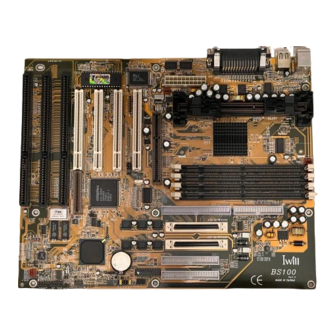
Page 8: Motherboard Components Placement
0.3 Motherboard Components Placement The following figure shows the location of the motherboard components. SB-LINK IRRX GNT# IRTX REQ# IRMODE 5VSB SIRQ LID-ON 1--2: SCSI Enable 2--3: SCSI Disable Tmp2 KB/MS J21-23 FAN2 SLOT1 Tmp3 FAN1 PCIx DIMM0~3 CH-B RAIDport II CH-A CH-B Tmp1... - Page 9 Location ScreenPrinting Description Slot1 Processor Slot 1 connector J5--J8 DIMM0--3 168-pin DIMM Sockets A.G.P. connector J12--J15 PCI1--4 PCI expansion slots RAIDport II Adaptec RAIDport II connector J21--J23 J21--J23 ISA expansion slots CH-A Narrow SCSI connector of Channel A CH-A Wide SCSI connector of Channel A CH-B Wide SCSI connector of Channel B IDE 0...
-
Page 10: Back Panel Connectors
0.4 Back Panel Connectors The following figure shows the location of the back panel I/O connectors, which include: PS/2-style keyboard and mouse connectors Two USB connectors Two serial port connectors One parallel port connector Parallel Mouse USB1 Keyboard Serial 1 Serial 2 USB0... -
Page 11: Form Factor
0.5 Form Factor The motherboard is designed to fit into an ATX form-factor chassis. The I/O connector locations and the mounting hole locations are in compliance with the ATX specification. Please see detail in the following figure. Datum (0, 0) 6 . -
Page 12: Chapter 1
Chapter 1 Quick Installation Several easy installation steps will be described in this chapter to help the experienced users with quick installation. If you are a beginner or need to know more about this product, refer to the Chapter 2. Step 1. - Page 13 Step 7. Connect the Speaker The 4-pin speaker header is located on pins 17--20 (marked as SPKR) of the front panel connector. Connect the speaker to this header. Signal of SPKR header Pin 17 Pin 18 Ground Pin 19 Pin 20 BUZZ Step 8.
- Page 14 Step 12. Connect the Power ON button All the ATX computer chassis provide a power on button. Connect the button to the header marked as “PWR ON”. Step 13. Install the Power Supply cord This motherboard provides the 20-pin ATX power connector. This works conjunction with the Power On button to provide remote On/Off function.
-
Page 15: Chapter 2
If possible, ground yourself by touching a metal table or your computer frame. Keep the board in its conductive wrapping until it is configured and ready to be installed in your system. 2.2 Unpack the BS100 You should find the following components when opening the box: One motherboard... -
Page 16: Installation Procedures
2.3 Installation procedures 2.3.1 Processor (Slot 1 and FAN1) The motherboard supports single Pentium ® II processor. The processor ’ s VID pins automatically program the voltage regulator on the motherboard to the required processor voltage. The motherboard currently supports processors that run internally from 233 MHz to 500 MHz. ®... - Page 17 Note: This jumper is able to provide more powerful functions, which are reserved for technician’s special testing purpose only. DO NOT use these functions unless you are an experienced user and you are willing to take your risk. Multiplier External Clock 100 MHz x 2.5 66 MHz...
- Page 18 Note 2. The Serial Presence Detect (SPD) information is highly recommended on all 100 MHz DIMMs for this motherboard. This function is implemented using an EEPROM component on the memory module. The nonvolatile storage device contains data programmed by the DIMM manufacturer that identifies the module type and various SDRAM organization and timing parameters.
- Page 19 2.3.8 Parallel port connector (LPT) The connector for the multi-mode parallel port is a 25-pin D-Sub connector located on the back panel. It is used for the printer or other parallel devices. Simply connect the parallel cable between devices and the parallel port connector. 2.3.9 Universal Serial Bus (USB) The USB is suitable for mid-to-low speed devices like mouse, keyboard, joystick...etc.
- Page 20 2.3.12 System fan header (FAN2 and FAN3) The system airflow is critical for system’s reliability. Airflow is determined by the size and number of fans and vents along with the placement in relation to the components and the airflow channels within the system.
- Page 21 2.3.14.3 RESET header (RST) The 2-pin reset header is located on pins 9--10 (marked as RST) of the front panel connector. It can be connected to a momentary type switch that is normally open. When the switch is close, the system will reset. Signal of RST header Pin 9 RESET...
- Page 22 sound card, enabling users to play real-mode DOS games. Connect the cable provided by PCI sound card to this connector. Signal of SB-LINK header Pin 1 GNT# Pin 2 Ground Pin 3 Pin 4 REQ# Pin 5 Ground Pin 6 SIRQ 2.3.16 Infrared connector (IR) Serial Port 2 can be configured to support an IrDA module connected to this connector.
- Page 23 2.3.20 System Hardware Monitor The system hardware monitor supports following features: Integrated temperature sensor to monitor system temperature Voltage sense monitoring to detect voltage level (+12 V, -12 V, +5 V, -5 V, +3.3 V) Fan speed sensors for up to three fans With a proprietary application, the system hardware monitor logic will check the voltage, temperature and fan speed all the time.
- Page 24 The following figure shows the correct SCSI bus topology. External Kit Int. Narrow Int. Wide Device Device Int. Wide Int. Narrow Device Device Terminator Ext. Device Ext. Device 8 bit cable 16 bit cable Narrow Wide Connector Connector 2.3.22 Adaptec RAIDport connector (RAIDPORT II) The onboard RAIDport II connector, in conjunction with an Adaptec ARO-1130CA-B RAIDport II card and the onboard SCSI controller, provides a complete client solution.
-
Page 25: Chapter 3
3.1.1 Upgrade BIOS The BIOS can be upgraded from a diskette with the Award Flash utility -- AWDFLASH.EXE. The BIOS image file and the update utility are available from Iwill’s WEB site: www.iwill.com.tw. 3.1.2 Recovering BIOS Data Some types of failure can destroy the BIOS. For example, the data can be lost if a power outage occurs while the BIOS being updated in flash memory. -
Page 26: Main Menu
<Esc> Quit from setup program without saving changes, or Exit from current menu page and return to main menu page <PgUp> or <+> Select the previous value for a field <PgDn> or <-> Select the next value for a field <F1>... -
Page 27: Standard Cmos Setup
INTEGRATED PERIPHERALS Specifies on-board controller features LOAD SETUP DEFAULTS Load the manufacturer default setting into CMOS SUPERVISOR / USER PASSWORD Specifies passwords IDE HDD AUTO DETECTION Auto-detect the parameters of IDE disks SAVE & EXIT SETUP Save current value to CMOS and exit setup EXIT WITHOUT SAVING Abandon all changes and exit setup 3.3 STANDARD CMOS SETUP... - Page 28 3.3.3.2 Cylinders If device TYPE is set to Auto, this field reports the number of cylinders for your hard disk and can not be modified. If the TYPE is set to User, you must type the correct number of cylinders for your hard disk. 3.3.3.3 Heads If device TYPE is set to Auto, this field reports the number of heads for your hard disk and can not be modified.
-
Page 29: Base Memory
3.3.5 Floppy 3 Mode Support 3 Mode floppy drive is a kind of 3.5 inches drive, which is used at NEC PC98 computer. It supports 1.2M and 1.44M format with the same drive. This field specifies which drive 3 Mode is supported. When a floppy drive is specified to support 3 Mode, the respective drive setting in “Drive A / Drive B”... -
Page 30: Bios Features Setup
3.3.10 Other Memory This refers to the memory located in the 640K to 1024K address space. This is memory that can be used for different applications. DOS uses this area to load device drivers in an effort to keep as much base memory free for application programs. -
Page 31: Boot Sequence
3.4.6 Boot Sequence This field configures the boot sequence of boot devices. Options Description A,C,SCSI (*) System will first try to boot from floppy drive then master IDE disk drive on primary channel and then SCSI disk drive C,A,SCSI Master IDE disk drive on primary channel, floppy drive, SCSI disk driver C,CDROM,A Master IDE disk drive on primary channel, ATAPI CDROM drive,... -
Page 32: Gate A20 Option
3.4.10 Gate A20 Option This field configures how the gate A20 is handled. The gate A20 is a device used to address memory above 1 Mbytes. Initially, the gate A20 was handled via a pin on the keyboard. Today, while keyboards still provide this support, it is more common, and much faster, for the system chipset to provide support for gate A20. -
Page 33: Chipset Features Setup
3.4.16 OS Select for DRAM >64MB When enabled, this field allows you to access the memory that over 64MB under OS/2. Options OS/2 Non-OS/2 (*) 3.4.17 Report No FDD For WIN 95 For a floppy diskless system that running Windows 95, this field should be set to Yes. Options No (*) 3.4.18 Video BIOS Shadow... -
Page 34: System Bios Cacheable
3.5.2 EDO DRAM Speed Selection This field selects pre-defined EDO DRAM timing for different speed categories. It is available only when the Auto Configuration field set to Enabled. Options Description 50ns Pre-defined timing for 50ns EDO DRAM 60ns (*) Pre-defined timing for 60ns EDO DRAM 3.5.3 EDO CASx# MA Wait State This field specifies the wait state of EDO DRAM address line. -
Page 35: Video Bios Cacheable
3.5.8 Video BIOS Cacheable When enabled, access to the video BIOS will be cached. Options Enabled Disabled (*) 3.5.9 Video RAM Cacheable When enabled, access to the video memory located at A0000H to BFFFFH will be cached. Options Enabled Disabled (*) 3.5.10 8 Bit I/O Recovery Time This field specifies the number of clocks, which the system will delay after the completion of an 8 bit input/output request. -
Page 36: Power Manegement Setup
3.5.15 AGP Aperture Size (MB) This field specifies the size of system memory that can be used for A.G.P. graphics aperture. Options 4 / 8 / 16 / 32 / 64 (*) / 128 / 256 3.5.16 Auto Detect DIMM/PCI Clk When enabled, the motherboard will automatically disable the clock source for a DIMM socket, which does not have a module on it. -
Page 37: Pm Control By Apm
3.6.2 PM Control by APM When enabled, an Advanced Power Management (APM) protocol will be activated to handle the power saving mode. Options Yes (*) 3.6.3 Video off Method This field specifies the method that video subsystem used for power saving. Options Description V/H SYNC+Blank (*) -
Page 38: Suspend Mode
3.6.8 Suspend Mode This field specifies the timer value of Suspend Mode. It is available only when the Power Management field set to User Define. Options 1 Min / 2 Min / 4 Min / 8 Min / 12 Min / 20 Min 30 Min / 40 Min / 1 Hour / Disable 3.6.9 HDD Power Down This field specifies the timer value for HDD power down. -
Page 39: Pnp/ Pci Configuration
Serial Port If enabled, timer will be reloaded when serial port is active. Parallel Port If enabled, timer will be reloaded when parallel port is active. 3.7 PNP/ PCI CONFIGURATION This setup page specifies Plug and Play and PCI features 3.7.1 PNP OS Installed The field specifies whether a Plug and Play operating system is installed. -
Page 40: Integrated Peripherals
3.7.5.1 Used MEM Length This field is available only when the Used MEM base addr field has been assigned to a base address. It specifies the memory size for the add-in card used. Options 8K (*) / 16K / 32K / 64K 3.7.6 Assign IRQ For USB When disabled, the BIOS will not assign IRQ channel to USB controller. -
Page 41: Usb Keyboard Support
3.8.3 IDE Primary Master / Slave Ultra DMA IDE Secondary Master / Slave Ultra DMA When selected Auto, the IDE controller will use Ultra DMA 33 Mode to access device if the device supports it. The maximum transfer rate of Ultra DMA 33 Mode is 33.3 MB/sec. Options Auto (*) Disabled... -
Page 42: Onboard Parallel Port
3.8.8 Onboard Parallel Port This field configures the onboard parallel port. There are several port addresses and IRQ channel that can be selected. Options Description 378 / IRQ 7 Port address 378h, IRQ 7 278 / IRQ 5 Port address 278h, IRQ 5 3BC / IRQ 7 Port address 3BCh, IRQ 7 Disabled... -
Page 43: Load Setup Defaults
3.9 LOAD SETUP DEFAULTS This setup page is used for loading the manufacturer default values. 3.10 SUPERVISOR / USER PASSWORD SETTING These setup pages are used for password setting. Note that the User Password can enter BIOS setup program, but has no rights to change the value of any fields. When a password has been enabled and the Security Option field is set as Setup, you will be prompted to enter the password every time you try to enter BIOS Setup program. -
Page 45: Scsi Bios Setup
Chapter 4 SCSI BIOS Setup 4.1 Introduction The motherboard has an configuration utility, SCSISelect, which allows you to change SCSI controller settings. SCSISelect also includes SCSI utilities that let you list the SCSI IDs of devices, format SCSI disk drives, and check them for defects. 4.1.1 Enter SCSISelect utility To enter the SCSISelect utility, boot the computer and press <Ctrl><A>... -
Page 46: Scsi Parity Checking
4.2.2 SCSI Parity Checking SCSI parity checking is a procedure used by the channel to verify the accuracy of data transfer on the SCSI bus. By default, parity checking is enabled on all channels. Disable parity checking for a channel if any SCSI device on the channel does not support SCSI parity. Options Enabled (*) Disabled... -
Page 47: Scsi Device Configuration
4.2.5 SCSI Device Configuration Press <Enter> to bring up SCSI Device Configuration menu. 4.2.5.1 Initiate Sync Negotiation Synchronous negotiation is a SCSI feature that allows the SCSI channel and its attached SCSI devices to transfer data in synchronous mode. Synchronous data transfer is faster than asynchronous data transfer. -
Page 48: Advanced Configuration Options
4.2.5.6 BIOS Multiple LUN Support When enabling, the SCSI BIOS support multiple LUN on a SCSI device. Otherwise, the SCSI BIOS can recognize LUN 0 only. Options no (*) 4.2.5.7 Include in BIOS Scan This field specifies whether the SCSI BIOS supports devices attached to the SCSI bus without the need for device driver software. - Page 49 Note that the data on all attached hard drives will be lost when you change from one scheme to another. You should use extended translation only with MS-DOS, Windows 95, Windows NT (FAT), OS/2 and you do not need to enable this option if you are using another operating system such as NetWare or UNIX.
-
Page 50: Scsi D Isk U Tilities
4.2.6.7 BIOS Support for Bootable CD-ROM When enabled, the SCSI controller supports booting from a CD-ROM drive. Options Enabled (*) Disabled 4.2.6.8 BIOS Support for Int 13 Extensions This field enables or disables support for disks with more than 1024 cylinders. In order to boot from “El Torito”...
Need help?
Do you have a question about the BS100 and is the answer not in the manual?
Questions and answers