Table of Contents
Advertisement
EC Declaration of Conformity
We
Iwill Corp.
No. 10, Wu Chuan 3rd Rd.,
Hsin Chuang City, Taipei,
Taiwan, R.O.C.
Declare under sole responsibility that the
BD100 Plus motherboard
Meets the intent of Directive 89/336/ECC for Electromagnetic Compatibility. Compliance was
demonstrated to the following specifications as listed in the official Journal of the European
Communities:
EN 50081-1 Emissions:
EN 55022
EN 55022
EN 60555-2 Power Harmonics
EN 50082-1 Immunity:
IEC
IEC
IEC
Radiated, Class B
Conducted, Class B
801-2 Electrostatic Discharge
801-3 RF Radiate
801-4 Fast Transient
1
Advertisement
Table of Contents

Subscribe to Our Youtube Channel
Related Manuals for IWILL BD100 Plus


Summary of Contents for IWILL BD100 Plus
- Page 1 Hsin Chuang City, Taipei, Taiwan, R.O.C. Declare under sole responsibility that the BD100 Plus motherboard Meets the intent of Directive 89/336/ECC for Electromagnetic Compatibility. Compliance was demonstrated to the following specifications as listed in the official Journal of the European...
-
Page 2: About This Manual
Keep this manual for your future upgrade or system re-configuration. Chapter 0 Overview An overview of some special and basic features of the BD100 Plus motherboard Chapter 1 Features The detailed features and specifications of the BD100 Plus motherboard... -
Page 3: Table Of Contents
Contents CHAPTER 0 ....................5 OVERVIEW ....................5 CHAPTER 1 ....................7 FEATURES....................7 1.1 F ....................7 EATURES 1.2 E ............... 9 NVIRONMENT EQUIREMENTS 1.3 M ........... 10 OTHERBOARD OMPONENTS LACEMENT 1.4 B ..............102 ANEL ONNECTOR 1.5 F .................. - Page 4 4.8 INTEGRATED PERIPHERALS ............46 4.9 LOAD SETUP DEFAULTS ..............50 4.10 IWILL SMART SETTING..............50 4.11 SUPERVISOR / USER PASSWORD SETTING......... 51 4.12 IDE HDD AUTODETECTION............52 4.13 SAVE & EXIT SETUP............... 52 4.14 EXIT WITHOUT SAVING..............52 CHAPTER 5 ....................53 SOFTWARE AND TOOLS ................
-
Page 5: Chapter 0
Keep this for your future reference. BD100 PLUS FEATURES The BD100 Plus is the newest, most exciting motherboard in the market today. A step ahead of the competition, the BD100 Plus provides more power, convenience, and reliability for users. The BD100 Plus has more speed, and is great for better, fast computer graphics. - Page 6 2000 date, and recognize the date format from other sources. Peripherals and Devices If you want to improve your system’s I/O performance, choose the latest Iwill SCSI controllers. The following are some Iwill SCSI controllers you may purchase and use with your BD100 Plus motherboard: SIDE 2930C: a fast SCSI for MO, CD-R, CD-R/W, CD-ROM.
-
Page 7: Chapter 1
Chapter 1 Features 1.1 Features 1.1.1 Processor ® Supports single Pentium III/II/Celeron processors Supports 100 MHz and 66 MHz bus speeds ® Supports all published Pentium III/II/Celeron processor voltages SEC (Single Edge Contact) cartridge Slot 1 connector Jumper inside selects the processor speed from 233 MHz to 500 MHz or higher 1.1.2 Core Logic Intel 82443BX PCI/ AGP controller Integrated DRAM controller... -
Page 8: Expansion Slots
1.1.4 Multi I/O Winbond W83977 super I/O controller Note: Several different chips of the W83977 series may be used to support special features. Supports two floppy disk drives (include 3 Mode drive) and / or QIC-80 tape drive Supports one multi-mode parallel port Supports two high speed 16550 FIFO serial ports Integrated keyboard controller Integrated PS/2 mouse controller... -
Page 9: Environment Requirements
1.2 Environment Requirements Temperature 0-55 degrees C (operating or storage) 5% to 95% non-condensing relative humidity At least a 250 W power supply The power supply must comply with the following recommendations found in the specifications: The potential relation between 3.3 VDC and +5 VDC power rails The current capability of the +5VSB line All timing parameters... -
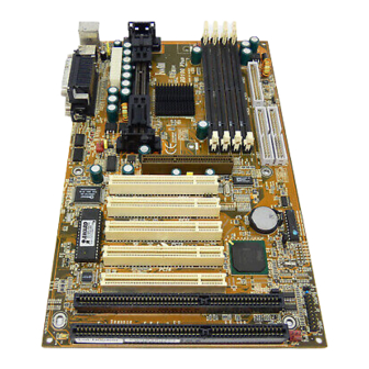
Page 10: Motherboard Components Placement
1.3 Motherboard Components Placement The following figure shows the location of the components on the BD100 Plus motherboard. IRRX 5VSB IRTX LID-ON IRMODE FAN2 Tmp2 GNT# REQ# SB-LINK SIRQ J21,J22 SLOT1 PCIx FAN1 DIMM0~3 JP42 JP10 PWR ON IDE0 JP11... - Page 11 Location Screen Printing Description Slot 1 Processor Slot 1 connector J5--J8 DIMM0--3 168-pin DIMM Sockets AGP connector J12--J16 PCI1--5 PCI expansion slots J21--J22 J21, J22 ISA expansion slots IDE 0 Primary IDE connector IDE 1 Secondary IDE connector Floppy drive connector Serial 1 connector Serial 2 connector Parallel connector...
-
Page 12: Back Panel Connector
1.4 Back Panel Connectors The following figure shows the location of the back panel I/O connectors, which include: PS/2-style keyboard and mouse connectors Two USB connectors Two serial port connectors One parallel port connector Parallel Mouse USB1 Keyboard Serial 1 Serial 2 USB0... -
Page 13: Form Factor
1.5 Form Factor The BD100 Plus motherboard is designed to fit into an ATX form-factor chassis. The I/O connector locations and the mounting hole locations are in compliance with the ATX specification. Please see details in the following figure: Datum (0, 0) 6.250... -
Page 15: Chapter 2
If you are a beginner, or need to know more about this product, please refer to Chapter 3. Note: Please reviews 1.3 Motherboard Components Placement graphic for reference. Warning: Users must follow these guidelines to ensure the BD100 Plus is protected during installation. Make sure your computer is unplugged whenever working with inside components. - Page 16 Step 3. Setting CPU speed The CPU speed is setup using Iwill Smart Setting. This is found in the BIOS setup by pressing <Del> during the boot up process. Please refer to Chapter 4 for instructions on setting CPU speed.
- Page 17 Step 7. Connect the Speaker The 4-pin speaker header is located on pins 17--20 (identified as SPKR. Connect the cable from the SPKR header to the speaker on the front panel of your PC case. Locate the SPKR header on the motherboard: Pin 17 Pin 18 Ground...
- Page 18 ATX power connector into the Power-On button. Step 13. Install the Power Supply cord The BD100 Plus motherboard provides a 20-pin ATX power connector. This works in conjunction with the Power-On button to provide remote On/Off function. Step 14. Install the Keyboard Connect the cable from the PS/2 keyboard connector at the back panel to the keyboard.
-
Page 19: Chapter 3
Hardware Installation 3.1 Preparation and Inspection The BD100 Plus motherboard, like all other electronic equipment, is sensitive to static. Please take the proper precautions when handling it. If possible, ground yourself by touching a metal table or desk. Keep the board in its conductive wrapping until it is configured and ready to be installed in your system. -
Page 20: Installation Procedure
3.3 Installation procedure 3.3.1 Processor (Slot 1 and FAN1) ® The BD100 Plus motherboard supports single Pentium III/II/Celeron processors. The processor’s VID pins automatically program the voltage regulator on the motherboard to the required voltage. The motherboard currently supports processors that run internally from 233 MHz to 500 MHz or higher. - Page 21 3.3.2 Setting CPU speed The CPU speed is setup using Iwill Smart Setting. This is found in the BIOS setup by pressing <Del> during the boot up process. Please refer to Chapter 4 for instructions on setting CPU speed. When adjusting frequency, select the frequency that matches your motherboard's bus speed in order to maximize your motherboard's performance.
- Page 22 Install DirectX 5 or later versions from Microsoft 3.3.5 Primary/Secondary IDE connectors (IDE0 and IDE1) The BD100 Plus motherboard has two bus-mastering IDE interfaces, which support PIO Mode 3 / 4 and Ultra DMA 33 mode transfer. These interfaces support IDE disks, ATAPI devices (ex: CD- ROM), ZIP and LS-120 devices.
- Page 23 Supports a maximum of 127 physical devices Supports data transfer rate up to 12 Mbit/sec The BD100 Plus motherboard has two USB ports; any USB peripheral can be connected to either port. For more than two USB devices, connect a hub to either port.
- Page 24 Locate the FAN2/3 header on the motherboard: Pin 1 Ground Pin 2 +12 V Pin 3 SENSE 3.3.13 Power-On header (PWR ON) The Power-On header can be connected to the Power-On button located on front panel of your PC case. Pressing this button turns your system on or off. At least two seconds must pass before the power supply will recognize another on/off signal.
- Page 25 3.3.14.4 KEYLOCK header (KL) If connected, the user is able to temporarily disable the keyboard (often used as security when the user steps away momentarily from the PC). The function is activated by pressing the keylock button on the front panel of the PC case. The 2-pin keylock header is located on pins 14--15 (identified as KL).
- Page 26 3.3.16 Infrared connector (IR) The Infrared connector supports infrared wireless transmitting and receiving of data between devices when using the appropriate application software. You must configure a Serial Port 2 to support an IrDA module prior to using this feature. The 7-pin Infrared header (identified as IR) is located in between the PCI1 and PCI2 slots.
- Page 27 3.3.20 Adjustable Vcore (JP9) This function offers adjustable processor Vcore. When NO jumper caps are used, the motherboard automatically generates the proper Vcore voltage that requested by the CPU. Place the jumper cap over pins 1-2 to increase 5% more voltage to the processor’s Vcore. Place the jumper cap over pins 2-3 to increase 10% more voltage to the processor’s Vcore.
- Page 28 100MHz 100MHz 100MHz Over-clocking at AGP 100MHz 112MHz 112MHz Over-clocking at CPU/AGP 100MHz 133MHz 133MHz Over-clocking at CPU/AGP CPU Type JP11 AGP Clock Remarks 66MHz 66MHz 44MHz Downgrade at AGP 66MHz 75MHz 50MHz Over-clocking at CPU, down grade at AGP 66MHz 83MHz 55MHz...
-
Page 29: Chapter 4
System BIOS Setup 4.1 Introduction The BD100 Plus motherboard uses AWARD BIOS, which is stored in flash memory and can be upgraded using the appropriate software program. The setup program is for viewing and changing the BIOS setting for a computer. These settings are stored in battery-backed RAM so that it retains all the settings after the power has been turned off. -
Page 30: Main Menu
4.1.4 Using BIOS setup program The following table shows the function keys available for each menu screen. áUp Move to the previous field âDown Move to the next field ßLeft Move to the field on the left hand side àRight Move to the field on the right hand side <Esc>... -
Page 31: Standard Cmos Setup
Specifies Plug and Play and PCI features INTEGRATED PERIPHERALS Specifies on-board controller features LOAD SETUP DEFAULTS Loads the manufacturer default setting into CMOS IWILL SMART SETTING Specifies special features SUPERVISOR / USER PASSWORD Specifies passwords IDE HDD AUTO DETECTION Auto-detects the parameters of IDE disks SAVE &... - Page 32 4.3.3.1 TYPE This field specifies type of drive that corresponds to the drive installed in your system. If you select User, please specify the correct number of Cylinders, Heads, and Sectors. Options Description 1 – 45 Specifies pre-defined disk drive type User Specifies disk drive type by user Auto...
- Page 33 4.3.4 Drive A / Drive B This field specifies the traditional type of the floppy drives. Options Description None No floppy drive is connected 360K, 5.25 in. A 360K floppy drive is connected 1.2M, 5.25 in. A 1.2M floppy drive is connected 720K, 3.5 in.
-
Page 34: Bios Features Setup
4.3.8 Base Memory The POST (Power-On Self Test) determines the amount of base (conventional) memory installed in the system. The value of the base memory is typically 640K. This field has no options. 4.3.9 Extended Memory The BIOS determines how much extended memory is present during the POST. This is the amount of memory located above 1MB in the processor’s memory address map. -
Page 35: Cpu L2 Cache Ecc Checking
4.4.4 CPU L2 Cache ECC Checking This field specifies whether the CPU L2 cache supports ECC or not. Options Enabled (*) Disabled 4.4.5 Quick Power-On Self Test When enabled, BIOS will shorten or skip some items during the Power-On Self Test (POST). Options Enabled (*) Disabled... -
Page 36: Swap Floppy Drive
4.4.8 Swap Floppy Drive When enabled, floppy drives A and B will be exchanged without the user physically changing the cable. Options Enabled Disabled (*) 4.4.9 Boot Up NumLock Status This field determines the configuration of the numeric keypad after system boot up. If On, the keypad uses numbers keys. -
Page 37: Security Option
4.4.14 Security Option This field configures how the system security is handled. It works conjunction with SETTING SUPERVISOR / USER PASSWORD page to control the security level of the system. Options Description Setup (*) System needs a password to enter BIOS setup program System System needs a password to boot 4.4.15 PS/2 mouse function control... -
Page 38: Chipset Features Setup
4.4.20 Video BIOS Shadow When enabled, the video BIOS will be copied to system memory and increase the video speed. Options Enabled (*) Disabled 4.4.21 C8000-CBFFF / CC000-CFFFF / D0000-D3FFF Shadow D4000-D7FFF / D8000-DBFFF / DC000-DFFFF Shadow When enabled, the extended ROM data located at the respective address range will be copied to system memory. -
Page 39: System Bios Cacheable
4.5.4 EDO RASx# Wait State This field specifies the Wait State of EDO DRAM row address line. This field is available only when the Auto Configuration field is disabled. Note: This field is for experienced users only. Options Description 2 (*) 2 system clocks wait state for EDO row address line 1 system clock wait state for EDO row address line 4.5.5 SDRAM CAS Latency Time... -
Page 40: Delayed Transaction
4.5.10 8 Bit I/O Recovery Time This field specifies the number of clocks, which the system will delay after the completion of an 8 bit input/output request. Options 1 (*) / 2 / 3 / 4 / 5 / 6 / 7 / NA / 8 4.5.11 16 Bit I/O Recovery Time This field specifies the number of clocks, which the system will delay after the completion of an 16 bit input/output request. -
Page 41: Power Management Setup
4.6 POWER MANAGEMENT SETUP This setup page specifies suspend or power saving features. There are several modes used to save computer’s energy: Doze Mode The CPU clock runs at slower speed, and all other devices still operate at full speed Standby Mode The CPU clock runs at slower speed, and the fixed disk drive will power off, and the video will power off, and all other devices... -
Page 42: Standby Mode
4.6.5 Standby Mode This field specifies the time the system enters Standby Mode. It is available only when the Power Management field is set to User Define. Options 1 Min / 2 Min / 4 Min / 8 Min / 12 Min / 20 Min 30 Min / 40 Min / 1 Hour / Disable (*) 4.6.6 Suspend Mode This field specifies the time the system enters power saving mode. -
Page 43: Wake Up On Lan
44.6.10 Suspend Mode Option This field specifies suspend mode options. Options Description Power-On Suspend (*) The traditional Green PC suspend mode. All devices except CPU will shut off. Suspend to Disk Saves system status, memory and screen image into hard disk, then the power turns off automatically. -
Page 44: Resume By Alarm
4.6.15 Power-On By Ring When enabled, the PC can power-on through an external modem connected to your PC. For example, you may send an e-mail message to your PC from another location, and this will power-on your PC. When using this feature, you must have a modem, and your PC must be turned off. Note: This feature alone doesn’t allow you to power off your PC (see 4.6.10 Suspend Mode). -
Page 45: Pnp/ Pci Configuration
4.7 PNP/ PCI CONFIGURATION This setup page specifies Plug and Play and PCI features. 4.7.1 PNP OS Installed The field specifies whether a Plug and Play operating system is installed. Options No (*) 4.7.2 Resources Controlled By The BIOS has the capability to assign system resources to all Plug and Play devices. However, this capability means absolutely nothing unless you are using a Plug and Play operating system such as ®... -
Page 46: Integrated Peripherals
4.7.5.1 Used MEM Length This field is available only when the Used MEM Base Addr field has been assigned a base address. It specifies the memory size for the add-in card used. Options 8K (*) / 16K / 32K / 64K 4.7.6 Assign IRQ For USB When disabled, the BIOS will not assign IRQ channel to USB controller. -
Page 47: Usb Keyboard Support
4.8.3 IDE Primary Master / Slave Ultra DMA IDE Secondary Master / Slave Ultra DMA If you select Auto, the IDE controller uses Ultra DMA 33 Mode to access UltraDMA-capable IDE devices. The maximum transfer rate of Ultra DMA 33 Mode is 33.3 MB/sec. Options Auto (*) Disabled... -
Page 48: Onboard Parallel Port
4.8.8 Onboard Serial Port 1 / 2 These fields configure the onboard serial ports. There are several port addresses and IRQ channels to select from. Options Description 3F8 / IRQ 4(*) Port address 3F8h, IRQ 4 2F8 / IRQ 3(*) Port address 2F8h, IRQ 3 3E8 / IRQ 4 Port address 3E8h, IRQ 4... -
Page 49: Init Display First
4.8.11 Init Display First This item allows you to decide which slot to activate first, either PCI slot or AGP slot. This function takes place during the system boot. Options PCI Slot AGP (*) 4.8.12 Power-On Function This field configures the Power-On mode of the system. If a power outage occurs, you need to re- configure this field. -
Page 50: Load Setup Defaults
4.9 LOAD SETUP DEFAULTS This setup page is used for loading the manufacturer default values. 4.10 IWILL SMART SETTING Warning: Over-clocking is not guaranteed. Users must have substantial knowledge of proper Vcore settings prior to adjusting CPU speeds. Over-clocking should be done only by experienced engineers who conduct tests. -
Page 51: Supervisor / User Password Setting
Option 3/3.5/4/4.5/5/5.5/6/6.5/7/7.5/8 4.10.2 Auto Detect DIMM/PCI Clk When enabled, the BD100 Plus motherboard will automatically disable the clock source for a DIMM socket, which does not have a module on it. This is true for all PCI slots. Options Enabled (*) Disabled 4.10.3 Spread Spectrum... -
Page 52: Ide Hdd Autodetection
message will confirm that the password is disabled. Once the password is disabled, the system will boot and you can enter setup program freely. Note: The User Password allows you to enter BIOS setup program, but you cannot change the value of any fields. -
Page 53: Chapter 5
You may simply select the software shown on screen that needs to be installed. Then simply follow the messages displayed on the screen to complete setup. Note: Iwill PowerInstaller does not support a keyboard at this moment. You must use a mouse to install it. -
Page 54: Installed
During the boot-up process, you can perform “Iwill Diskette Creator,” which will automatically make the driver diskettes you need. Note: At least one CD-ROM drive and one 1.44M floppy drive are necessary to make “Iwill Diskette Creator” work properly. -
Page 55: View Detailed Manual
This Power Installer CD includes detailed information of all Iwill manuals for every motherboard manufactured by Iwill. Please insert the Iwill Power Installer CD into the CD-ROM drive; the Auto Run program will display the main manual automatically. Click the “View Manual” item, and select the product you want to view, and the manual will be displayed. - Page 56 Enable CD-ROM Bootable and Set boot sequence first priority is CD-ROM. Place the Iwill Power Installer CD into the CD-ROM drive Boot from Iwill Power Installer to create Windows 9x/NT driver diskette from CD- ROM by selecting FMS Disk1 for Win95/NT Place the Windows NT 4.0 CD-ROM in the drive.
-
Page 57: Installing The Suspend To Disk Utility On Your Bd100 Plus
“Suspend to Disk” diskette to use for installation. Insert the Power Installer CD into your CD-ROM, select Make Driver Diskette from the menu, and carefully follow the instructions to make a driver diskette. Please see Chapter 5.2 in the BD100 Plus manual to create a driver diskette without an operating system. - Page 58 Power-on the system by either pressing the Power-On button, or by using any of the power-on features provided by the BD100 Plus motherboard. Then, press the <Del> key after the Power-On Self Test (POST), and before the scanning of IDE devices. Simply look for the message “Press DEL to enter SETUP”...
- Page 59 sure you have enough disk space before selecting either option (Please refer to System Requirements above). Creating a file stores all the necessary information (you may be working on) into a hidden read-only file within the system hard disk. Creating a partition allows further protection for you by storing all the necessary information into partition separate from other files.
- Page 60 5.6.2 Using Suspend to Disk There are two ways to use Suspend to Disk: Simply press the power-on button located on the front panel of your computer chassis. Note: Do not hold the power-on button more than four seconds, because the system will shutdown immediately, and the Suspend to Disk function will not work.
- Page 61 5.6.3.2 Delete Suspend to Disk From DOS Directly Enter DOS during the re-boot process by pressing the <F8> key after powering on the system, and selecting “Command prompt only.” Or, if your system normally runs from DOS, or you have a DOS diskette, simply boot from DOS.
-
Page 62: How To Use The Thermal Sensor
5.7 How to use the Thermal sensor Detects all heat-releasing devices. Firmly screw the connector to any device. Detects system temperature. NO NEED to contact this thermostat to any device. Leave it on the motherboard. -
Page 63: Iwill Scsi Series
5.8 Iwill SCSI series If you want to improve I/O performance of your BD100 Plus, choose the latest Iwill SCSI controllers. The following are some Iwill SCSI controllers you may purchase, and use with your BD100 Plus motherboard: SIDE 2930C:... - Page 64 Up to 12 meters cable length for Ultra 2 devices Able to connect up to 15 devices Able to boot from any SCSI ID Able to boot from CD-ROM Please contact Iwill today for more information regarding our SCSI cards.
Need help?
Do you have a question about the BD100 Plus and is the answer not in the manual?
Questions and answers