Table of Contents
Advertisement
Quick Links
Table of Content
Quick Installation .................................................. 3
Feature .................................................................. 10
Hardware Setup ................................................... 13
KD266 Version 1.1A
1
FB11325000000
Advertisement
Table of Contents

Related Manuals for IWILL KD266


Summary of Contents for IWILL KD266
-
Page 1: Table Of Contents
Table of Content Quick Installation ..........3 Before Installation Layout Item Checklist Jumpers/ Connectors Form Factor Feature ..............10 Block Diagram Specifications Hardware Setup ........... 13 Install the Processor Install Memory Modules Back Panel KD266 Version 1.1A FB11325000000... -
Page 2: Bios Setup
Standard CMOS Features Advanced BIOS Features Advanced Chipset Features Integrated Peripherals Power Management Setup PnP/ PCI Configurations PC Health Status Iwill Smart Setting Load Fail Safe Defaults Load Optimized Defaults Set Supervisor/ User Password Setting Save & Exit Setup Exit Without Saving... -
Page 3: Quick Installation
Chapter 1 Quick Installation Quick Ins tallation Before Installation For installation, you m ay need som e or all of the follow ing tools: M edium size flat blade screw driver M edium size P hillips head screw driver A 3/16 inch nut driver or w rench Users must follow these guidelines to ensure the motherboard is protected during installation. -
Page 4: Layout
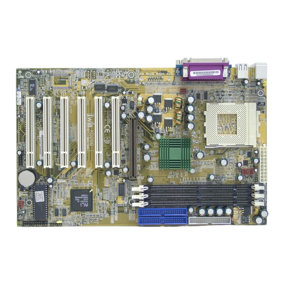
Chapter 1 Quick Ins tallation Layout PS2_ SB Fcpu Socket462 Fcpu CPU Socket Faux KD266 PCI1 PCI2 PCI3 PCI4 M 1 5 3 5 D + PCI5 PCI6 Fsys Tsys Item Checklist The motherboard Operation manual A TA/66/100 cable Floppy cable... -
Page 5: Jumpers/Connectors
Chapter 1 Quick Installation Jumpers/Connectors DRAM Voltage (VIO) PS2_SB(JP6) Disabled Enabled (Default) Normal (Default) Increase 5% Increase 10% Clear CMOS Normal (Default) C l e a r C M O S System temp CPU fan PIN Assignment 1:GND Auxiliary fan 2:12V 3:Sense System fan... - Page 6 Chapter 1 Quick Installation Wake On Modem 1 2 3 PIN Assignment 1:5VSB 2:GND 3:Control Pin Wake On LAN 1 2 3 PIN Assignment 1:5VSB 2:GND 3:LAN_Wake Infrared connector(IR) PIN Assignment 1:VCC 2:FIR 3:IRRX 4:GND 5:IRTX 6:OVCR OFF...
- Page 7 Chapter 1 Quick Installation ATX power connector P I N N O Definition P I N N O Definition +3.3v +3.3V +3.3v -12V G R O U N D G R O U N D Power Supply On G R O U N D G R O U N D G R O U N D G R O U N D...
- Page 8 Chapter 1 Quick Installation Front panel connector PIN NO. Function Definition PWR_ON(Power/Soft_off) 1,13 PIN 7:Anode ALED(IDE LED) PIN 8:Cathode PIN 11:RST RST(RESET) 11,12 PIN 12:GND PIN 15:VCC PLED(System Pow er LED) 15,16,17 PIN 16:NC PIN 17:GND PIN 21:VCC PIN 22:NC SPKR(Speaker) 21,22,23,24 PIN 23:NC...
-
Page 9: Form Factor
Chapter 1 Quick Installation P I N Form Factor Socket462 KD266 M1535D+ 193mm... -
Page 10: Feature
Chapter 2 Feature Feature Block Diagram Sock 462 CPU AGP 4X/2X ALi M 1649 Memory Bus SDRAM North Bridge PCI Bus Clock Generator ALi M 1535D+ PCI x 6 Ultra DMA/66/100 Keyboard/Mouse Floppy Parallel Serial Game Port... -
Page 11: Specifications
Chapter 2 Feature Specifications Processor / (Socket A) Supports 1 processor Socket A Supports 100MH z/133MH z (Front Side Bus) Supports AMD Athlon and D uron C P U CPU Frequency/Voltage Selection Supports V core selection by BIOS (1.125V to 1.85V Step 0.025V) Supports VIO selection by Jum per (5% or 10%) Supports C P U Multiplierselection by BIOS (5X to 15X Step 0.5X) Supports C P U E xternal Frequency selection by BIOS(100MH z-180MH z... - Page 12 Chapter 2 Feature Management Supports voltage m onitoring (+12V/+5V/Vcore/+3.3V) Supports fan control signal (C P U /SYS) Supports tem perature sensor (C P U /SYS) Supports P ower on by E xt.Modem /Int.Modem /R TC /P ME Supports R esum e by LAN /E xt.Modem /Int.Modem /P S2Keyboard/P S2 Supports AC P I Supports AP M/D MI/SMBU S/P nP Supports BIOS R OM Flash C ontrol...
-
Page 13: Hardware Setup
Chapter 3 Hardware Setup Hardware Setup Install the Processor The CPU should have a fan attached it to prevent overheating. Be sure that there is sufficient air circulation across the processors heatsink by regularly checking that your CPU fan is working. Without sufficient circulation, the processor could overheat and damage both the processor and the motherboard. - Page 14 Chapter 3 Hardware Setup Step5: Attach the heatsink to the CPU. Be careful not to scrape the motherboard when mounting a clampstyle processor fan or else damage may occur to the motherboard. Step6: Pu sh th e c lip o f h eat si nk downward to hock the ear of socket firmly.
-
Page 15: Install Memory Module
Chapter 3 Hardware Setup Install Memory Module The m otherboard h as three m em ory sockets and supp orts m em ory size up to 3GB. Step2: Step1: Open latches of DIMM socket. Proofread the RAM module to the DIMM Socket. -
Page 16: Back Panel
Chapter 3 Hardware Setup Back Panel Function color Description This connector can be used to support a PS2/Mouse Green PS/2 mouse. This connector can be used to support a PS2/keyboard Purple PS/2 keyboard. This motherboard has two USB ports, any Universal Serial Black USB-compatible peripherals and/or hub... - Page 17 The BIOS can be upgraded from a diskette w ith the Aw ard Flash utility — AWDFLASH.E XE . The BIOS im age file, and update utility are available from IWILL’ s WE B site: support.iwill.net If you have any problem, please contact with us in IWILL’ s web site:www.iwill.net Enter BIOS setup program...
- Page 18 1-2 again. it returns the R TC to the default se tting. Then, get into the BIOS setup program , ch oose Load Fail-Safe D efaults ; Load Optim ized D efaults, and select IWILL’ s E ngineers to set default settings in your C MOS.
-
Page 19: Main Menu
A brief description of each highlighted selection appears on the bottom of the screen. CMOS Setup Utility-Copyright(c) 1984-2001 Award Software Standard CMOS Features IWILL Smart Setting Advanced BIOS Features Load Fail-Safe Defaults Advanced Chipset Features Load Optimized Defaults... -
Page 20: Standard Cmos Features
Chapter 4 BIOS Setup Standard CMOS Features CMOS Setup Utility-Copyright(c) 1984-2001 Award Software Standard CMOS Features Date (mm:dd:yy) Fri, Jan 5 2001 Item Help Time (hh:mm:ss) 15:17:48 IDE Primary Master [None] Menu Level IDE Primary Slave None] IDE Secondary Master None] Change the day, month, year and century... - Page 21 Chapter 4 BIOS Setup I DE Pr imar y M as ter / Pri mary Slave / Second ary M aste r / Secondary Slave This field specifies type of drive that corresponds to the driver installed in your system. If you select User, please specify the correct number of Cylinders, Heads, and Sectors.
- Page 22 Chapter 4 BIOS Setup Drive A / Drive B This field specifies the traditional type of floppy drives. None Any Floppy drive is connected (*Drive B default) 360K, 5.25 in. Specifies extended CHS translation mode 1.2M, 5.25 in. A 1.2M floppy drive is connected 720K, 3.5 in.
- Page 23 Chapter 4 BIOS Setup Halt On Each time the BIOS detects a non-fatal error, All Errors the system will stop and display an error (Default Value) message. The system will stop for any errors that are No Errors detected. The system will stop for any errors except All, But Keyboard keyboard error.
-
Page 24: Advanced Bios Features
Chapter 4 BIOS Setup Advanced BIOS Features CMOS Setup Utility-Copyright(c) 1984-2001 Award Software Advanced BIOS Features Item Help [Disabled] [Enabled] [Enabled] Menu Level [Disabled] [Enabled] Allows you to choose [Floppy] the VIRUS warning [HDD-0] feature for IDE Hard [SCSI] Disk boot sector [Enabled] protection. - Page 25 Chapter 4 BIOS Setup Virus Warning When this function is enabled and any attem pt to write data into this area is m ade, the BIOS m onitor will display a warning m essage on screen and beep. If you want to run an anti-virus program , we recom m end you that it will disable and appear the Virus Warning function beforehand.
- Page 26 Chapter 4 BIOS Setup Boot Up Floppy Seek Seek disk drives during boot up. D isabling speeds boot up. [ E n a b l e (Default Value),D isabled] Boot Up NumLock Status This field determ ines the configuration of the num eric keypad after system boot up.
- Page 27 Chapter 4 BIOS Setup Security Option This field configures how the system security is handled. It works conjunction with SE TTIN G SU P E R VISOR / U SE R PASSWOR D page to control the security level of the system . [Setup (Default Value):System needs a password to enter BIOS setup program .] [System :System needs a password to boot]...
-
Page 28: Advanced Chipset Features
Chapter 4 BIOS Setup Advanced Chipset Features This setup page is used to specify advanced features available through the chipset. The default settings have been chosen carefully for m ost operating conditions. D O N OT change the value of any field in this setup page without full understanding. - Page 29 Chapter 4 BIOS Setup DRAM Timing Select The first chipset settings deal with C P U access to dynam ic random access m em ory (D R AM). The default tim ings have been carefully chosen and should only be altered if data is being lost. Such a scenario m ight well occur if your system had m ixed speed D R AM chips installed.
- Page 30 Chapter 4 BIOS Setup Video RAM Cacheable Setting to enabled, access to the Video R AM will be cached. [E nable,D isabled(Default Value)] AGP Aperture Size This field configures the m ain m em ory size for AGP graphics data used.
-
Page 31: Integrated Peripherals
Chapter 4 BIOS Setup Integrated Peripherals CMOS Setup Utility-Copyright(c) 1984-2001 Award Software Integrated Peripherals OnChip IDE Channel0 [Enabled] Item Help [Enabled] OnChip IDE Channel1 Primary Master [Auto] Menu Level Primary Slave [Auto] Secondary Master PIO [Auto] [Auto] Secondary Slave Primary Master UDMA [Auto] Primary Slave... - Page 32 Chapter 4 BIOS Setup 3.3 MB/sec PIO Mode 0 5.2 MB/sec PIO Mode 1 PIO Mode 2 8.3 MB/sec PIO Mode 3 11 MB/sec PIO Mode 4 16.6 MB/sec Auto(Default Value) Negotiated with device automatically Mode 0 Use Mode 0 timing to access device Mode 1 Use Mode 1 timing to access device Mode 2...
- Page 33 Chapter 4 BIOS Setup Pow er-On Function This field configures the P ower-On m ode of the system . The P ower-On button will not function in this m ode. Password You can assign a password string through KB Power-On Pass word field. Y ou can assign a hot key through the Hot Key Hot KEY Power-On field.Pressing this hot key will power-...
- Page 34 Chapter 4 BIOS Setup Onboard Serial Port 1 / 2 / 3 These fields configure the onboard serial ports. There are several port addresses and IR Q channels to select from . 3F8 / IRQ 4 Port address 3F8h, IRQ 4 (Default Vaule) Port address 2F8h, IRQ 3 2F8 / IRQ 3...
- Page 35 Chapter 4 BIOS Setup Parallel Port Mode This field configures the operating m ode of an onboard parallel port. E nsure you know the specifications of your parallel port devices before selecting field. [SP P (Default Value),E P P,E C P E C P +E P P ] ECP Mode Use DMA When the P aral lel P ort Mode field is configured as E C P, E C P +E P P m ode, it needs a D MA channel for data transfer.
-
Page 36: Power Management Setup
Chapter 4 BIOS Setup Power Management Setup CMOS Setup Utility-Copyright(c) 1984-2001 Award Software Power Management Setup Power Mangemen [User Define] I t e m H e l p PM Control by APM [No] M O D E M U s e I R Q t [3 ] Menu Level Video Off In Suspend... - Page 37 Chapter 4 BIOS Setup Pow er Management This feature allows the user to select the default param eters for the power-saving m ode. Min Saving: When idle for one hour,the system enters suspend m ode. Max Saving: When idle for fifteen m inutes, the system enters suspend m ode. U ser D efine(Default Value): U ser can specify the tim e the system enters suspend m ode.
- Page 38 Chapter 4 BIOS Setup APM Suspend Timer This field specifies the tim e the system enters power-saving m ode. It is available only when the P ower Managem ent field is set to U ser D efine. [1Min,2Min,4Min,8Min,12Min,20Min,30Min,40Min,1H our, D isabled(Default Value)] PWR-Off Mode by PWR-BTTN This field specifies the function of power button.
- Page 39 Chapter 4 BIOS Setup PnP/ PCI Configurations CMOS Setup Utility-Copyright(c) 1984-2001 Award Software PnP/PCI Configurations PNP OS Installed [No] Item Help Reset Configuration Data [Disabled] Menu Level Resources Controlled By [Auto (ESCD)] IRQ Resources Press Enter Select Yes if you are using a Plug and Play PCI/VGA Palette Snoop [Disabled]...
- Page 40 Chapter 4 BIOS Setup Resources Controlled By The Award P lug and P lay BIOS has the capacity to autom atically configure all the boot and P lug and P lay com patible devices. H owever, this capability m eans a bsolutely nothing unless you are using a P lug and P lay operating system such as Windows98/95/ N T.
-
Page 41: Pc Health Status
Chapter 4 BIOS Setup PC Health Status This page is the current status of your com puter. On the screen displays CP U/System tem perature, FAN speed and voltages. CMOS Setup Utility-Copyright(c) 1984-2001 Award Software PC Health Status Item Help CPU Warning Temperature [Disabled] Current CPU Temperature... -
Page 42: Iwill Smart Setting
FSB speed. Auto Detecting CPU speed: IWILL MicroStepping will auto detect the C P U 's factory m ultiplier setting and C P U FSB to the factory default. This function provides a "fuss free" C P U set up process for the general users. - Page 43 BIOS Setup Micro Adjustable CPU FSB speed: IWILL provides a user friendly overclocking function that allows users to experience the fun of overclocking. This function allows user to adjust C P U FSB by 1MH z interval. This is particularly useful when user wants to extract the m ost out of the purchased C P U .
- Page 44 P ressing ‘ Y’ loads the BIOS default values for the m ost stable, m inim al-perform ance system operations. CMOS Setup Utility-Copyright(c) 1984-2001 Award Software Standard CMOS Features IWILL Smart Setting Advanced BIOS Features Load Fail-Safe Defaults Advanced Chipset Features...
- Page 45 When you press <E nter> on this item you get a confirm ation dialog box with a m essage sim ilar to: CMOS Setup Utility-Copyright(c) 1984-2001 Award Software Standard CMOS Features IWILL Smart Setting Advanced BIOS Features Load Fail-Safe Defaults Advanced Chipset Features...
- Page 46 . CMOS Setup Utility-Copyright(c) 1984-2001 Award Software Standard CMOS Features IWILL Smart Setting Advanced BIOS Features Load Fail-Safe Defaults Advanced Chipset Features Load Optimized Defaults...
- Page 47 BIOS Setup Save & Exit Setup Save current C MOS value and exit BIOS setup program . CMOS Setup Utility-Copyright(c) 1984-2001 Award Software Standard CMOS Features IWILL Smart Setting Advanced BIOS Features Load Fail-Safe Defaults Advanced Chipset Features Load Optimized Defaults...
- Page 48 BIOS Setup Exit Without Saving Abandons all C MOS value changes and exits BIOS setup program . CMOS Setup Utility-Copyright(c) 1984-2001 Award Software Standard CMOS Features IWILL Smart Setting Advanced BIOS Features Load Fail-Safe Defaults Advanced Chipset Features Load Optimized Defaults...
Need help?
Do you have a question about the KD266 and is the answer not in the manual?
Questions and answers