Table of Contents
Advertisement
Quick Links
KNIGHT
Top 3D Equipment
Instruction Manual
*
Hardened hollow main shaft
*
Dual pin tail rotor pitch system
*
Thrust bearings built in tail grips
*
CCPM swash controls
*
Q
uick to build
*
Hardcore 3D out of box
*
-
Fully Ball Raced
* + /-
.
o
12 5
collective pitch range for extreme 3D
*
Extra tough frame design
*
Vibration insolation engine mount.
*
High efficiency direct belt drive system
*
High CG design
*
-
Push pull control
:
:
Gear Ratio
1 8 7 4 8
:
Blade Length
600 620mm
:
Engine
50 size
-
Take off Weight
Fuel Tank Capacity
As we continue to improve our products. This manual may not reflect all recent product amendments. Please refer to the received product and
.
.
.
.
.
.
.
:
.
-
(
):
.
no fuel
3 3kg
:
400cc
check our website:
3D
*
*
*
*
CCPM
*
*
*
*+/ -
*
*
.
*
*
*
www.compassmodel.com
,
,
www.compassmodel.com
,
.
,
12 5
.
: : . : .
1 8 7 4 8
:
600 620mm
-
:
50
: . 3 3kg
:
400cc
:
.
3D
Advertisement
Table of Contents

Related Manuals for Compass Knight 3D


Summary of Contents for Compass Knight 3D
-
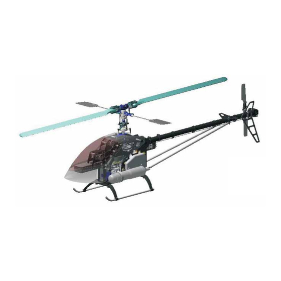
Page 1: Instruction Manual
KNIGHT Top 3D Equipment Instruction Manual Hardened hollow main shaft Dual pin tail rotor pitch system Thrust bearings built in tail grips CCPM CCPM swash controls uick to build Hardcore 3D out of box Fully Ball Raced * + /- *+/ - 12 5 12 5... -
Page 2: The Meaning Of Symbols
Introduction Thank you for choosing the Knight 3D and welcome to Compass Model. The Knight 3D has been carefully designed to offer out standing flight performance and includes many innovative features along with proven components to provide you with a model which is accurate, durable and agile. - Page 3 Obtain assistance from experienced pilots Certain level of skill is required to operate R C helicopter The Guidance provided by experienced pilots is valuable and sometimes necessary for assembly tuning and flights It is also recommended that you practice with a computer based flight simulator Keep a safe distance when operating During operation the main blades and tail blades on a r c helicopter spin at a very high rate of speed The blades are capable of inflicting serious bodily damage or injury to yourself or others Keep the model at a safe...
- Page 4 Necessary Items Not Included In this Package Battery...
-
Page 5: Standard Equipment
Standard Equipment This model is packed according to assembling steps Do not open all the bags at one time Open only one bag for each step of assembly when building 。 。 。 Canopy Long items Frame Set Rotor Head Step 1 Step 2 Step 3... -
Page 6: Step 1 Landing Gear Installation
Assembling Always apply blue Loctite when fixing Bolts on Metal parts Always apply green Loctite where Bearings fit in Metal parts Do not over tight Self Tapping Bolts into plastic otherwise plastic part could be damaged Step 1 Landing Gear Installation Frame Set Pre assembled in Factory M3 Washer x4... - Page 7 Note Apply special engine tool when fixing Fan Hub on the engine And make sure Fan Hub Set is M3x10 firmly tightened on the Engine 05 9001 Engine Tool M3 Washer Hex Wrench M3x16 Socket Head Bolt M3x8 M3 Nylon Nut .
- Page 8 Drill here Gear Case Tail Boom Longer Groove To avoid any tail gear case rotation drill a hole in the There are 2 grooves in the Boom. There is a lug inside the boom through the guide hole on the tail gear case and Tail Gear Case.
-
Page 9: Step 4 Main Gear Installation
Step 4 Main Gear Installation M3 Nylon Nut Mast Collar M3x10 Socket Head M3 Nylon Nut x1 Bolt Upper Bearing M3x25 Socket Block M3x25 Socket Head Bolt x Head Bolt M3x25 Note The Mast Collar is installed underneath the upper bearing block M3x10 Socket Head Bolt x 1 M3x10 Rotate the tail drive belt 90°... - Page 10 Step 5 Rotor Head, Washout & Swashplate Installation M3x3 Set Screw M3 Nylon Nut x1 Paddle M3x22 Socket Head Bolt x1 M3x22 M3x3 Set Screw X2 M3x3 M3x22 Socket Head Bolt 8x16x5 Bearing Washout Set Swash Plate 8x16x5 Thrust Bearing Main Shaft 8x16x5 Bearing Thrust Bearing Direction...
- Page 11 Step 6 Servo & ESC Installation M2 5 Washer x16 M2 Nut x7 M2x6 Socket Head Bolt x7 M2 5x16 Self Tapping Screw x16 M2x6 M2 5x16 M2 5 Servo Nylon Servo Nut M2 Nut Link Bal M2 5x16 Self Tapping Screw M2x6 Socket Head Bolt M2 5 Washer...
- Page 12 Step 7 Electronic Devices Arrangement Step 7 Electronic Devices Arrangement Rudder Servo Elevator Servo Pitch Servo Gyro Aileron Servo Receiver Switch Battery Throttle Servo Please check first your radio manuals before connecting these electronic devices Hitec as shown below. Futaba Aileron Elevator Throttle...
- Page 13 Step 8 Phasing Control Ring Adjustments Main Grip Washout Arm Parallel to the Boom Boom Phasing Control Ring Main Grips Phasing Block Washout Arm Gets the right phasing adjustment by turning the phasing control ring until the washout arms and main grips would be parallel to the tail boom.
-
Page 14: Pitch Curve
If Ball Links are too tight to resize tight ball links only use the Compass Model ball link sizing tool (E-XQT-01) The Ball Link Sizing Tool is very sharp use it with caution do not over size Ball Links and do not adjust with pliers... - Page 15 Step 11 Servo Direction Check Turn on the radio position the heli tail point to yourself Make sure radio is set to 120 degree CCPM mode Move the stick and check the reaction of the Swash Plate Throttle and Tail Pitch Plate Adjust radio settings accordingly 120 ccpm...
- Page 16 Step 12 Setup Parallel Make sure the Flybar Control Arm and Paddle are in line as in the diagram Then start to setup A Turn on the radio set throttle to middle position for 0 degree Use the subtrim in radio program to adjust all the servo to get control horn to the right angle "...
- Page 17 C Next adjust the links from T Arms to Swash Plate to level Swash Plate A compass Swash Washout Arm Plate Tool can be applied here as a guide Horizontal Swash Plate D Set the Washout Arms horizontal Horizontal °...
-
Page 18: Step 13 Canopy Installation
Step 13 Canopy Installation Drill holes after checking correct position 。 This Mark is only a guide please put the canopy on the heli frame to obtain the exact position before drilling the hole here 。 。 Cut along this line Drill a hole on this mark. - Page 19 Decal Check belt direction When Main Blades turn clockwise tail blades should turn clockwise when view from the Tail Fin side If not the belt is installed incorrectly...
-
Page 20: Pre-Flight Check
Make sure all electronic devices are firmly fastened and connected Before starting the motor make sure the IDLE switch is OFF and Throttle stick is in the low position IDLE Only turn off the transmitter after turning off the receiver Compass Model Limited www compassmodel com... - Page 21 Compass Model Hong Kong www compassmodel com Knight 3D Instruction Manual Copyrights Dec 2007...
Need help?
Do you have a question about the Knight 3D and is the answer not in the manual?
Questions and answers