Table of Contents
Advertisement
Quick Links
Technical information
Installation instructions
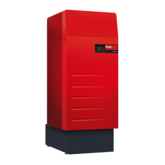
UltraGas
(1550)
®
Gas condensing boilers
for natural gas in modulating operation
Hoval products must be installed and commissioned
by specialists only. These instructions are intended for
service engineers. Electrical installation must be per-
formed by a licensed electrical company.
Subject to modifi cations
|
4 217 901 / 02 - 07/19
Frontbild
27.08.2018 / O.Müller
4217901
Vertical gas condensing boilers UltraGas
to EN 15502-1/15502-2-1 are suitable and licensed for
use as heat generators for hot water heating systems
with a permissible flow temperature of up to 90 °C
They are designed for continuously controlled reduced
operation in heating systems.
See technical data
1)
These instructions are applicable to the fol-
lowing types:
Nominal output ranges at 40/30°C
and natural gas
45-UltraGas
(1550)
®
328-1550 kW
(1550) acc.
®
.
1)
EN
Advertisement
Table of Contents

Related Manuals for Hoval UltraGas 1550


Summary of Contents for Hoval UltraGas 1550
- Page 1 (1550) 328-1550 kW ® Frontbild 27.08.2018 / O.Müller 4217901 Hoval products must be installed and commissioned Vertical gas condensing boilers UltraGas (1550) acc. ® by specialists only. These instructions are intended for to EN 15502-1/15502-2-1 are suitable and licensed for service engineers.
-
Page 2: Table Of Contents
TABLE OF CONTENTS Important notices General safety instructions ..............................4 Explanation of the symbols ..............................4 1.2.1 Warnings ..................................4 1.2.2 Warning symbols................................4 1.2.3 Information ..................................5 On delivery ...................................5 Warranty ....................................5 Manuals ....................................5 Regulations, standards, ordinances to be complied with for proper use......................6 Installation Set-up ....................................7 Installation of the thermal insulation ..........................10... - Page 3 TABLE OF CONTENTS Maintenance Safety instructions ................................37 Deaeration ..................................37 Top up with water ................................37 Renewing fuse ...................................37 Information for fire inspector / chimney sweep regarding emission and manual operation settings ......38 Cleaning .....................................39 6.6.1 Cleaning the burner cylinder (inside and out) ........................39 6.6.2 Cleaning the combustion chamber and burner cylinder on the outside ................40 6.6.3...
-
Page 4: Important Notices
IMpORTANT NOTICES Important notices Explanation of the symbols 1.2.1 Warnings General safety instructions The system may only be placed in operation if DANGER all the relevant standards and safety regulati- ... indicates a situation of immediate danger ons have been complied with. which will lead to serious or fatal injuries if not avoided. -
Page 5: Information
Refers to standards and directives. Manuals All instructions relevant to your system can be found in the Hoval system manual - please keep all manuals! In exceptional cases, the instructions can be found with the components! Further sources of information: •... -
Page 6: Regulations, Standards, Ordinances To Be Complied With For Proper Use
IMpORTANT NOTICES Regulations, standards, ordinances to be Austria § • ÖNORM EN 12828 Heating systems in buildings - De- complied with for proper use sign of hot water heating systems The locally applicable heating system regulations must • ÖNORM EN 12831 Energy efficiency of buildings - be followed when planning, installing and operating the Method for calculation of the design heat load gas heat generator:... -
Page 7: Installation
INSTAllATION Installation Set-up WARNING The boiler must only be suspended using the four points marked as the crane suspension option in Fig. 02. The hooks on the back of the boiler must not be used to suspend it. Space requirement of UltraGas (1550) ®... - Page 8 INSTAllATION UltraGas (1550) with shortened boiler feet ® (All dimensions in mm) UltraGas ® Type (1550) 2457-2507 UltraGas (1550) with walled-in pedestal and adjustable feet ® UltraGas ® Type (1550) 2455-2505 1 Neutraliser / condensate box 2 Condensate pump 3 Walled base 4 Adjustable feet 30-80 mm UltraGas (1550) with walled-in pedestal without adjustable feet...
- Page 9 INSTAllATION Procedure: 1. Remove front (5, Fig. 02) and rear (1) wooden crossbeam. 2. Using a winch (6), raise the front of the boiler. 3. Remove both side beams (2) to the front and side (see Fig. 02). 4. Push in front feet (3) and mount both front cover brackets (4). 5.
-
Page 10: Installation Of The Thermal Insulation
INSTAllATION Installation of the thermal insulation Place the insulation mat (1, Fig. 03) around the UltraGas (1550) boiler and attach with plastic straps (1a, Fig. 03) and ® strap fasteners (1b, Fig. 03). - Tension springs (1c, Fig. 03) are used for additional fixing - Do not overtighten the straps (reduced insulating value). -
Page 11: Overview Of Casing Sections
INSTAllATION Overview of casing sections The figure below shows the order in which the casing sections are mounted. Chapter “2.4 Fitting the casing” describes in detail the individual work steps of the mounting process for attaching the casings. Cable duct Side wall front with special screws Side wall back... -
Page 12: Fitting The Casing
Fitting the casing 1. Hook the cable duct (1, Fig. 04) into the threaded pins on the left and right and attach with the second hexagon nuts and washers (1a) from the front already mounted on the boiler. If there is a side wall support (2, detail A), turn outwards to the side. - Page 13 Before hooking in the front cover (23), first take the steps listed in chapter “2.5 Fitting the pedestal ca- sing”. 14 a 13 a 13 a Detail C Exhaust gas sensor Mains cable Condensate box (if fitted) Water pressure sensor Pressure switch B17, B18 Flame monitoring (ionisation)
-
Page 14: Fitting The Pedestal Casing
INSTAllATION Fitting the pedestal casing Attach the syphon (18, Fig. 07), which is sup- plied loose, including double nipple (18a). 11. Place the condensate box (option) under the boiler and establish the electrical connection. Make the condensate drain or connection line according to se- parate instructions. -
Page 15: Technical Information
(1550) is a low-pollution and ener- ® gy-saving gas condensing boiler with the Ultraclean bur- ner system, a gas-fired pre-mix burner with combustion air fan. The Hoval UltraGas (1550) has a vertically arran- ® ged combustion chamber of stainless steel as the primary... -
Page 16: Meaning Of The Data On The Data Plate
Hoval s.r.l. I-24050 Zanica Hoval d.o.o. HR-10250 Lučko Hoval EOOD BG-1797 Sofia Vendita Hoval GmbH D-85609 Dornach Hoval SK spol. s r.o. SK-040 01 Košice Sale Hoval spol. s r.o. CZ-312 04 Plzen Hoval s.r.l. RO-Voluntari 077190, Jud IIfov Hoval SAS F-67118 Geispolsheim Hoval Sp. -
Page 17: Ultragas ® (1550) Technical Data
TECHNICAl INFORMATION UltraGas (1550) technical data ® Type (1550) • Nominal heat output at 80/60°C, natural gas 298-1472 • Nominal heat output at 40/30°C, natural gas 328-1550 • Nominal heat output 80/60 °C, propane • Nominal heat output 40/30 °C, propane •... -
Page 18: Dimensions / Space Required
TECHNICAl INFORMATION Dimensions / space required (All dimensions in mm) <( => 0:::: >- >- Notice For required space, see chapter 2.1. Fig. 11 10. Kondensatablauf mit Geruchsverschluss und Verschraubung für Kunststoffrohr 1. Vorlauf Heizung Heating flow Condensate drain with odour trap and screw connection for plastic pipe 11. -
Page 19: Overall Unit Dimensions
TECHNICAl INFORMATION 3.4.1 Overall unit dimensions Boiler without casing and insulation WARNING The boiler must only be suspended using the four points marked as the crane suspension option in Fig. 02. The hooks on the back of the boiler must not be used to suspend it. Fig. -
Page 20: Boiler Flow Resistance
® only works in conjunction with the TopTronic E/UG hea- ® Hoval UltraGas® (1550) ting controller. The automatic function device takes over the functions for correct operation of a modulating gas boiler. These are some properties that are integrated in the au- tomatic function device: •... -
Page 21: Installation
INSTAllATION Installation Requirements on the boiler room Safety instructions Regarding the building specifications for boi- § ler rooms, regulations specific to the state or country are to be observed. CAUTION Regarding the ventilation of boiler rooms, re- Cutting injuries as a result of sharp edges. gulations specific to the state or country are to Handle parts of the casing carefully and avo- be observed. -
Page 22: Exhaust Gas Connection, Exhaust Gas Line
INSTAllATION Exhaust gas connection, exhaust gas • The cross sections and the maximum line lengths are calculated with reference to dia- Due to the low exhaust gas temperature, condensate grams or tables. The tables are available from forms in the exhaust gas line and wind protection equip- the exhaust gas line manufacturer. -
Page 23: Condensate Drain
INSTAllATION Condensate drain Option 3 + 4 (with outflow at a higher level) The boiler condensate drain must be made of • KB 24 Neutraliser box with pump corrosion-resistant including neutralisation material. The following materials are suitable • KB 22 Condensate box with pump for condensate discharge: •... -
Page 24: Gas Connection
TECHNICAl INFORMATION Gas connection Hydraulic connection According to EN 12828:2003, the following safety-techni- cal equipment is integrated into the boiler: DANGER • Minimum pressure limiter DBmin Danger of explosion due to leaking gas con- • Safety maximum pressure limiter DBmax nection. -
Page 25: Hydraulic Integration
Actuator, mixer 2 • Install sacks to prevent single-pipe gravity circulation! NOTICE • An automatic air vent (AAV) must be ins- Please close unused connections tightly. talled before the shut-off valve. This is not supplied by Hoval. 4 217 901 / 02... -
Page 26: 4.6.2.2 Cascades
4.6.2.2 Cascades Procedure to remove the front casing 1. Remove front cover (1, image 18) after first releasing As a basic principle, the Hoval TopTronic E should per- ® the lateral locking bolt (1a) (turn approx. ¼ turn to the form cascade control. -
Page 27: Safety Precaution For Installation In Line With Emc Requirements
TECHNICAl INFORMATION 4.8.1 Safety precaution for installation in line • Measures must be taken in the building and on electri- cal equipment to protect the units against overvoltage with EMC requirements caused by lightning strikes. • The mains connection for the heating system must be •... - Page 28 TECHNICAl INFORMATION In the case of star-shaped data bus networks, double To ensure correct electrical installation, unit connec- tion and equipotential bonding (energy supply com- earthing is not permitted. The earthing must be carried out on one side at the star point. pany and building installation), all applicable laws, regulations and standards must be complied with;...
-
Page 29: Recommended Cable Cross-Sections And Maximum Permitted Cable Lengths
TECHNICAl INFORMATION 4.8.2 Recommended cable cross-sections and maximum permitted cable lengths Line type Cross-section Length Electrical supply of min. 2.5 mm the heat generator unlimited m with 16 A fuse (230 V) Electrical supply of min. 2.5 mm the heat generator unlimited m with 16 A fuse (400 V) -
Page 30: Initial Commissioning
• Risk of injury for non-expert personnel. • Initial start-up, maintenance and cleaning work are only allowed to be performed by trained specialist personnel or by Hoval customer service. NOTICE Damage to the system by filling unauthorised liquids. -
Page 31: Water Quality
In particular, attention must be paid to the following stipu- lations: Filling and replacement water • Hoval boilers and calorifi ers are designed for heating • For a plant using Hoval boilers untreated drinking water plants without signifi cant oxygen intake (plant type I ac- is generally best suited as heating medium, i.e. -
Page 32: Venting The Gas Pipe
INITIAl COMMISSIONING Venting the gas pipe Functional check of pressure monito- ring device Comply with the necessary regulations when § venting the gas pipe. WARNING Lack of combustion air and exhaust gas ac- cumulation can result in injury to persons. •... -
Page 33: Checking Pressure In The Burner Cylinder ( Safety Check)
6. Tighten upper screw on pressure switch B17. The settings must only be changed by a spe- 7. Correct pressure switch B17 or B18 settings if neces- cialist trained by Hoval or by Hoval customer sary (if the measured value differs more than 10% service. -
Page 34: Setting The Gas Quantity, Measuring The Co ) And Nox/Co Content In The Exhaust Gas
1. Start the “Emission” menu on the control module. tion must only be made by a specialist trained - The control automatically switches to normal ope- by Hoval or by Hoval customer service. ration after expiration of the remaining runtime or after pressing the “Reset” button. -
Page 35: Activation Of Screed Function
INITIAl COMMISSIONING Activation of screed function Description of function The control module of the TopTronic E contains a functional sequence used for drying out screed fl oors. To start the ® screed drying, it is necessary for the individual functions to be set accordingly. Flow temperature Heating-up phase Inertia phase... - Page 36 INITIAl COMMISSIONING Function display Icon Function Screed drying active Various settings can be made as well. Prioritisation of the screed func- tion means the settings are only ac- tive at the end of the function. Information remaining run time Request of the active function phase, the ACT temperature as well as the remaining run time.
-
Page 37: Maintenance
Maintenance and cleaning work are only al- licensed electrician. lowed to be performed by trained specialist personnel or by Hoval customer service. 1. Set the blocking switch to “0” and disconnect the heat generator from the mains (main switch, fuse). -
Page 38: Information For Fire Inspector / Chimney Sweep Regarding Emission And Manual Operation Settings
MAINTENANCE Information for fire inspector / chimney sweep regar- ding emission and manual operation settings This chapter is exclusively intended to describe the function of emissions and manual operation settings for the fi ring monitoring technician / chimney sweep. All operating elements are described in the operating instructions. CAUTION Danger of scalding with hot water, since the hot water temperature can exceed the target setpoint temperature. -
Page 39: Cleaning
The boiler is only allowed to be cleaned by a licensed specialist or Hoval customer service technician. The Hoval gas boiler must be cleaned and serviced at least once a year. NOTICE If the Hoval gas boiler was in operation during the building phase, it is essential to check the degree of contamination. -
Page 40: Cleaning The Combustion Chamber And Burner Cylinder On The Outside
MAINTENANCE 11. Clean the premix burner inside and out with com- Preparation: pressed air or thoroughly flush with water. 12. Remove released dust and dirt particles with a vacu- WARNING um cleaner (4, Fig. 27). The heat generator must be de-energised for maintenance. -
Page 41: Cleaning/Adjusting Ignition And Ionisation Devices
MAINTENANCE Fig. 30 Fig. 29 6.6.3 Cleaning/adjusting ignition and ionisation Cleaning: devices • Spray combustion chamber and aluFer pipes (3, Fig. ® The distance between the ionisation elec- 30). trode and the burner cylinder must be ap- - The best results are achieved with a spray gun and a prox. -
Page 42: Setting The Gas Quantity, Measuring The Co ) And Nox/Co Content In The Exhaust Gas
MAINTENANCE Setting the gas quantity, measuring the CO ) and NOx/CO content in the exhaust gas (see chapter 5.8). Cleaning the syphon 21-UltraGas (850) Sifon • Release the syphon and remove it from the boiler. • Rinse the syphon. • Check syphon seal (1, Fig. 33) for damage and replace Fig. -
Page 43: Maintenance For Neutraliser / Condensate Box For Type Kb 22, Kb 23 And Kb 24 (If Present)
Neutralisation granulate for refi lling the neutraliser box can be ordered from Hoval under the following item no.: Neutraliser box Type KB 23 • 1 pack (3 kg) neutralisation granules Part no. -
Page 44: Repair Pressure Monitoring Device
WARNING Test port The settings must only be changed by a spe- cialist trained by Hoval or by Hoval customer service. 1. Check seat of the screw connections between pres- Sealing plug sure switch B18 and the burner cover:... -
Page 45: Bic 960 Automatic Function Device´parameter List
6.11 BIC 960 automatic function device´parameter list WARNING Changes to the BIC may only be made by authorised Hoval customer service technicians. The following table is intended solely to provide information for the Hoval customer service technician! 6.11.1 UltraGas (1550) automatic function device ®... - Page 46 MAINTENANCE Parameters Description Unit Level System setting values 45-UG (1550) 33 2FL 32801 Fan ramp-up during operation rpm/s 34 2FM 32802 Fan ramp-down during operation rpm/s 35 2FN 32803 Fan follow-on time after a lock-out 36 2FO 32804 Fan speed after shut-down 1600 in normal operation or when locked 37 2FR 32805 Fan follow-on time after operation...
- Page 47 4 217 901 / 02...
- Page 48 COPY FOR PLANT USER Confirmation The user (owner) of the system herewith confi rms that • he has received adequate instruction in the operating and maintenance of the installation, • received and taken note of the operating and maintenance instructions and, where applicable other documents con- cerning the heat generator and any further components.
Need help?
Do you have a question about the UltraGas 1550 and is the answer not in the manual?
Questions and answers