Table of Contents
Advertisement
Quick Links
Technical information
Installation instructions
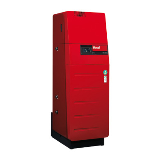
UltraOil
(16-35)
®
Oil condensing boiler
This appliance is
only suitable for
operation with
heating oil EL
(low sulphur)
Hoval products must be installed and commissioned
only by appropriately qualified experts. These instruc-
tions are intended exclusively for the specialist. Elec-
trical installations may only be carried out by a qualified
electrician.
Subject to modifi cations
|
4 210 255 / 02 - 01/14
These instructions are applicable to the fol-
lowing types:
Rated output levels at 40/30ºC
32-UltraOil
(16)
®
32-UltraOil
(20)
®
32-UltraOil
(25)
®
32-UltraOil
(35)
®
with TopTronic
The UltraOil
heating boiler is suitable for and approved
®
as a heating unit for hot-water systems with permitted
flow temperatures up to 90 °C
for closed circuits, but is equally suitable for installation
in open circuits.
see point 3.2
1)
T controller
®
. It is designed primarily
1)
EN
Advertisement
Table of Contents

Related Manuals for Hoval UltraOil 16


Summary of Contents for Hoval UltraOil 16
- Page 1 This appliance is only suitable for operation with heating oil EL (low sulphur) Hoval products must be installed and commissioned The UltraOil heating boiler is suitable for and approved ® only by appropriately qualified experts. These instruc- as a heating unit for hot-water systems with permitted tions are intended exclusively for the specialist.
-
Page 2: Table Of Contents
TABLE OF CONTENTS Important information Other instructions ................................4 Safety instructions ................................4 Warranty ....................................5 Assembly Set-up, levelling ...................................6 Fitting the burner .................................6 Condensate discharge ................................9 2.3.1 Design variants .................................9 Fitting the condensate drain (standard design) .......................10 Fitting the neutralisation box (Option) ..........................11 Fitting the condensate delivery pump (Option)........................12 Fitting the neutralisation box and the condensate delivery pump (option) ..............13 Fitting the flue gas silencer (Option) ..........................15... - Page 3 TABLE OF CONTENTS Maintenance Information for combustion controller/chimney sweep regarding emission monitor key ..........30 Cleaning the boiler ................................31 6.2.1 Preparations for cleaning the boiler and burner .......................31 6.2.2 Re-assembling the boiler ..............................31 Cleaning the combustion chamber and the aluFer pipes ....................33 ®...
-
Page 4: Important Information Other Instructions
All instructions relevant to your system can be found in lations. the Hoval system manual! In exceptional cases, the in- • ÖNorm B 8131 Closed hot water systems, safety, con- structions can be found in the documentation for the com- struction and testing regulations. -
Page 5: Warranty
IMPORTANT INFORMATION Warranty Fault-free operation can only only be guaranteed if these instructions are followed and if the boiler is regularly ser- viced by a licensed specialist (maintenance contract). The rectification of faults and damage as a result of con- taminated operating materials (gas, water, combustion air), unsuitable chemical additives to the heating water, improper handling, faulty installation, unauthorised modi-... -
Page 6: Assembly
ASSEMBLY Assembly Fitting the burner 1. Remove the absorber hood (1, Fig. 02), after first re- Set-up, levelling leasing the lateral locking bolt (2) (turn approx. ¼ turn The boiler is fixed to wooden transport chocks. For trans- to the left and pull out as far as the stop). port up and down stairs, it is wise to leave these timbers in place under the boiler. - Page 7 ASSEMBLY Assembly aid: To simplify installation, the sealing on the burner flange can be lubricated using a heat-resistant paste (e.g. Klu- berpaste UH1 84-201). Screw head Fig. 06 6. Fix the burner in position by tightening the screw (3, Fig. 03). Insulate the cavity between burner pipe and boiler flange with the fireproof fibre provided.
- Page 8 ASSEMBLY 8. The oil lines can be routed through the absorber hood on the right or left side. 9. Establish the plug-in connections (4, Fig. 08). Pull the plug cables out further by releasing the high-strength cable glands (5). - The burner must be connected to the boiler with the standard plug-in connection.
-
Page 9: Condensate Discharge
ASSEMBLY Condensate discharge Possibility 3 -see chapter 2.6 • Siphon and condensate delivery pump • Without neutralisation, condensate discharge into high- The condensate discharge must be manu- er drain line. factured of corrosion-resistant material. The following materials are suitable for the con- densate discharge: PVC, PE, PP, ABS Local regulations pertaining to the conden-... -
Page 10: Fitting The Condensate Drain (Standard Design)
ASSEMBLY Fitting the condensate drain (standard Fit drain (5) on siphon (3) and lead it outwards (op- tionally left or right side) through the aperture (5a). design) 6. Fit connecting line (5) to the drain line (2m hose en- 1. Remove front cover (1a, Fig. 13). Release lateral closed with the boiler). -
Page 11: Fitting The Neutralisation Box (Option)
ASSEMBLY Fitting the neutralisation box (Option) 5. Fit rear cover (4, fFig. 17) of the neutralisation box. 6. Fit jubilee clip (5) approx. 20mm from the upper end 1. Remove the neutralisation box from its packaging. of the hose and tighten slightly. The hose (5a) of the Remove the front and rear cover of the neutralisation connection eccentric (5b) must be aligned towards box. -
Page 12: Fitting The Condensate Delivery Pump (Option)
ASSEMBLY Fitting the condensate delivery pump (Op- tion) Install the condensate delivery pump (11,Fig. 22) as shown in the drawing. Fig. 19 9. Slightly loosen the jubilee clip (8, Fig. 20) and push it upwards. Firmly tighten the jubilee clip (connection must be sealed). -
Page 13: Fitting The Neutralisation Box And The Condensate Delivery Pump (Option)
ASSEMBLY Fitting the neutralisation box and the con- 3. Remove front cover (2a, Fig. 25). Release lateral locking bolt (1, Fig. 22) (turn approx. ¼ to the left and densate delivery pump (option) pull out as far as the stop). Lift the front cover straight upwards and remove towards the front. - Page 14 ASSEMBLY 7. Slide the neutralisation box (6, Fig. 27) into the boiler 11. Fill the neutralisation box with water. until the hose of the siphon (5a, Fig. 26) is directly 12. Fit the front cover (9, Fig. 30) of the neutralisation beneath the drain connection.
-
Page 15: Fitting The Flue Gas Silencer (Option)
ASSEMBLY Fitting the flue gas silencer (Option) The silencer must be installed vertically. The maximum permissible angle of inclination is 45°! Fig. 31 4 210 255 / 02... -
Page 16: Technical Information
® of the following directives + standards Description of the boiler We hereby declare that the product described, as an in- The Hoval UltraOil is a low-pollutant, energy-saving ® dividual unit, complies with the standards, guidelines and oil-fired heating boiler. The UltraOil has a combustion ®... -
Page 17: Technical Data
• Delivery pressure at flue gas outlet • Maximum chimney draught Flow resistance boiler in mbar = flow rate (m Data valid for Hoval oil compact heat station b-i Data without silencer, can be reduced by fitting a silencer Flue gas silencer... -
Page 18: Dimensions Ultraoil ® (16-35)
TECHNICAL INFORMATION Dimensions UltraOil (16-35) ® (All dimensions in mm) Heating flow / safety flow R1" Low-temperature return R1" High-temperature return R1" Flue gas outlet DN80 Boiler controller Condensate drain (left or right) incl. siphon DN25 and 2 m PVC continuous-flow tube inner Ø 19 x 4 Fig. -
Page 19: Space Requirement Ultraoil (16-35)
TECHNICAL INFORMATION Space requirement UltraOil (16-35) ® min. 100 with silencer Fig. 34 Boiler door incl. burner swings upward and to the left or outward. minimal 150 mm * Brennerserviceposition vorne - Kesselreini- gung von rechts optimum 300 mm * - Burner service position left - boiler cleaning from the front - A minimum gap of 160 mm is required to the... -
Page 20: Installation
INSTALLATION Installation Flue gas connection and chimney 4.2.1 Project planning instructions Boiler room requirements Regarding the building specifications for boiler rooms and their supply and extract air handling, the current build- ing supervisory office regulations specific to the state or The flue gas must be routed through a country are to be observed. -
Page 21: Example Of A Flue Gas Conduit
Inspektions-T- - Eco heating oil low-sulphur SN 181 160-2 / 2008 T-piece Stück einzusetzen If an existing oil heating installation is replaced by a Hoval UltraOil , the following instructions regarding the oil tank ® and its refilling must be observed:... -
Page 22: Electrical Connection
INSTALLATION Electrical connection 1. Schalldämmhaube (1, Fig. 23) abnehmen, dazu seitliche Sicherungsbolzen (2) lösen (ca. ¼- Drehung The electrical connection must be established by a li- links und bis Anschlag herausziehen). censed and qualified electrician. 2. Untere Frontabdeckung (3) abnehmen, dazu seitliche Sicherungsbolzen (4) lösen (ca. -
Page 23: Safety Measures Relating To Emc Assembly
INSTALLATION 4.4.1 Safety measures relating to EMC assembly 1. For regulator units with their own power supply, sepa- rate laying of power leads and sensor or bus-leads is absolutely essential. If using cable channelling, only that fitted with separator strips may be used. 2. -
Page 24: Flue Gas Performance Diagrams
INSTALLATION Flue gas performance diagrams The diagrams show the flue gas temperature characteristics with Hoval burners. UltraOil (16) ® Flow 80 °C/ return flow 60 °C Flow 40 °C/ return flow 30 °C °C °C UltraOil (20) ® Flow 80 °C/ return flow 60 °C Flow 40 °C/ return flow 30 °C... -
Page 25: Hydraulic Integration
INSTALLATION Hydraulic integration it is not necessary to neutralise condensate from an oil-fired condensing unit of up to 120 Examples kW drained together with domestic waste Direct heating circuit water from a private household. For the UltraOil , the fuel used must be heat- ®... -
Page 26: Commissioning
8.3 and 9.5 after 6-12 weeks of heating operation. In particular, attention must be paid to the following stipu- lations: • Hoval boilers and calorifi ers are designed for heating Filling and replacement water plants without signifi cant oxygen intake (plant type I ac- •... -
Page 27: Filling The Heating System
COMMISSIONING Filling the heating system Filling of the heating system must be carried out by trained personnel. The fill and make-up water must comply with the quality requirements in the relevant state or country (see chapter 5.1). Filling the water heater (if fitted) The heating boiler may be put into operation even when the water heater is not filled. - Page 28 COMMISSIONING Cross where applicable; cut out record and fasten to the control during the active screed function. Minimum requirements for the activation of the screed function: Minimum age cement screed 21 days Minimum age calcium sulphate screed 7 days Flow temperature monitor installed and connected For newly laid screed - see „Recommendation of the Federal Association of Radiant Panel Heating“.
- Page 29 COMMISSIONING Parameter 16 „Screed function“ (Parameter HC, MC1 or MC2) Example: Maximum fl ow temperature 40°C 1 Function heating Starting day + 7 days [°C] VLSol 55°C maximum set level! maximal 55°C einstellbar! 1=Funktionsheizen 1 = Function heating Funktionsheizen START DAYS START 1 9 10 11 12 13 14 15 16 17 18 19 20 21 22 23 24 25 26 TAGE]...
-
Page 30: Maintenance
MAINTENANCE Maintenance Information for combustion controller/chimney sweep regarding emission monitor key All other control elements of the control unit are described in the operating instructions. The emission monitor key can also be used to change over to manual operating mode. Emission monitor key / Manual operation To protect under fl oor heating systems against invalid overheating during emis-... -
Page 31: Cleaning The Boiler
• Replace absorber hood (1) and attach with locking bolt tenance contract with Hoval customer service, or with an (turn approx. ¼ turn to the right). authorised specialist dealer. - Page 32 MAINTENANCE Fig. 42 Design with condensate discharge Design with neutralisation box (if fitted) Mount hose for Fig. 43 Fig. 44 wet cleaning 4 210 255 / 02...
-
Page 33: Cleaning The Combustion Chamber And The Alufer Pipes
• A special cleaning set (contains four cleaning scrap- ers) to remove stubborn dirt build-up is available from Hoval, Art. No. 6022 844. • Before removing the drain hose, all dirt particles must be adequately rinsed out of the condensate drip tray. -
Page 34: Servicing The Neutralisation Installation (If Fitted)
Neutralisation granulate for refi lling can be ordered from Hoval under the following item no.: • 1 pack (3 kg) neutralisation granules Part no. 2028 906 Procedure for servicing the neutralisation installation •... -
Page 35: Safety Temperature Limiter - Reset
MAINTENANCE Safety temperature limiter - Reset Fig. 45 Boiler water temperature limiter - Reset If the boiler temperature rises too high (>100 °C), the system is switched off by the safety temperature limiter by means of a mechanical lockout. Press the reset button on the control panel (first remove the cover): the boiler is ready for operation again once the boiler water temperature is less than 80 °C. -
Page 36: Resetting The Fault Message "Flue Gas Stl" Or Flue Gas Temperature Limiter Unblocking
MAINTENANCE Resetting the fault message “Flue gas STL” 6.6.2 Flue gas temperature limiter - reset or flue gas temperature limiter unblocking (if no flue gas sensor is fitted) If the flue gas temperature rises too high, the system is 6.6.1 Resetting the fault message “Flue gas STL” switched off by the flue gas safety temperature limiter by means of a mechanical lockout. -
Page 37: Overview Of Settings Table Of Parameters
OVERVIEW OF SETTINGS Overview of settings Table of parameters Regulator Setting range / Designation Factory Setting values Type of device: DHW: Address: Surface operation Key : Heating curve HC OFF, 0,20 ..3,5 Heating curve MC1 OFF, 0,20 ..3,5 Heating curve MC2 OFF, 0,20 .. - Page 38 OVERVIEW OF SETTINGS Table for Time programs DHW circuit Time program P1 Time program P2 Time program P3 Cycle 1 Cycle 2 Cycle 3 Cycle 1 Cycle 2 Cycle 3 Cycle 1 Cycle 2 Cycle 3 from from from from from from from...
- Page 39 OVERVIEW OF SETTINGS HYDRAULIC Par. Designation Factory Lev. Function allocation of the output DHW charging pump Function allocation of the output Mixer circuit 1 Function allocation of the output Mixer circuit 2 Function allocation of the output Direct circuit Pump Function allocation of the variable output 1 Function allocation of the variable output 2 OFF/ 4/ 43...
- Page 40 OVERVIEW OF SETTINGS Par. Designation Factory Lev. DHW-NIGHT DHW - economy temperature 40/ 45 °C DHW-legionella protection-day 2:00 DHW-egionella protection-time 50/ 55/ 65/ DHW-legionella protection-temperature 70 °C DHW-temperature recording 50/ 55/ 65/ DHW-maximum temperature limit 70 °C DHW-mode of operation ON/ OFF DHW-tank discharge protection DHW-charging temperature excess...
- Page 41 OVERVIEW OF SETTINGS MIX. VALVE-1 Par. Designation Factory Lev. Type of reduced operation ECO/ ABS MK= 1,10 Heating system (exponent) Room override (in connection with room sensor) Room factor 100 % Adaptation heating curve Switch-on optimisation Heating limit Room frost protection limit 10 °C Room thermostat function Outside temperature allocation...
- Page 42 OVERVIEW OF SETTINGS MIX. VALVE-2 Par. Designation Factory Lev. Type of reduced operation ECO/ ABS MK= 1,10 Heating system (exponent) Room override (in connection with room sensor) Room factor 100 % Adaptation heating curve Switch-on optimisation Heating limit Room frost protection limit 10 °C Room thermostat function Outside temperature allocation...
- Page 43 OVERVIEW OF SETTINGS HEAT GENER. Par. Designation Factory Lev. H-GEN model 1/ 2/ 5 OFF/ 3 Start-up protection H-GEN 5/ 48/ 65/ 75 Minimum temperature limit H-GEN °C 75/ 85 °C Maximum temperature limit H-GEN Mode of action minimum temperature limit H-GEN 5 °C Sensor mode operation for H-GEN Minimum burner running time...
- Page 44 OVERVIEW OF SETTINGS RETURN CONTR Par. Designation Factory Lev. Minimum limit return temperature / reference value return 38 °C temperature Switch-off difference Pump follow-on time 1 min SOLAR Par. Designation Factory Lev. Switch-on difference 10 K Switch-off difference Minimum running time SOP 3 min Solar collector maximum temperature 100 °C...
- Page 45 OVERVIEW OF SETTINGS BUFFER Par. Designation Factory Lev. Minimum temperature 5/ 20 °C 95 °C Maximum temperature 8/ 10/ 12K Temperature elevation, H-GEN Switching difference 2/ 5/ 10K Forced discharge Skimming function switch-on difference 10 K Skimming function switch-off difference Start-up protection Discharge protection Buffer mode of operation...
- Page 46 OVERVIEW OF SETTINGS SERVICE Par. Designation Factory Lev. Service 1 (Cleaning ST1 ) Suspend message «CLEANING ST-1» for X days Cleaning according to fi xed date Cleaning according to fi xed interval Cleaning according to cleaning counter Reset cleaning display 1 Service 2 (Cleaning ST2) Suspend message «CLEANING ST-2»...
-
Page 47: Fault Reporting Overview Toptronic ® T
OVERVIEW OF SETTINGS FAULT REPORTING OVERVIEW TopTronic ® Status Designation Fault type Code Remark System External sensor Interruption 10-0 System External sensor Short-circuit 10-1 System Boiler sensor Interruption 11-0 System Boiler sensor Short-circuit 11-1 System Flow sensor 1 Interruption 12-0 MC1=off, YK1=no current System Flow sensor 1... - Page 48 Regulator with address 10 is System Activity 70-8 missing System Activity Data bus error 70-9 No Hoval regulator System HP return sensor Return min. temp. below setpoint 85-4 System HP return sensor Return max. temp. exceeded 85-5 Heat source min. temp. below...
- Page 49 4 210 255 / 02...
- Page 50 COPY FOR PLANT USER Confirmation The user (owner) of the system herewith confi rms that • he has received adequate instruction in the operating and maintenance of the installation, • received and taken note of the operating and maintenance instructions and, where applicable other documents con- cerning the heat generator and any further components.
Need help?
Do you have a question about the UltraOil 16 and is the answer not in the manual?
Questions and answers